Page is loading ...

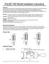
Models: 10137, 10138, 10139, 10140
Important: READ INSTRUCTIONS CAREFULLY BEFORE INSTALLING. KEEP THESE INSTRUCTIONS FOR FUTURE
REFERENCE.
WARNING - Risk of re or electric shock.To reduce the risk of electrical shock, re, or injury to persons; read and follow
all warnings and installation instructions before installing. All installation should be performed by a qualied electrician.
Ensure power is off before installation or inspection. All wirings are performed in accordance with Electrical Code and local
electrical code.
WARNING - Make certain power is switched OFF before starting installation or attempting any maintenance. Consult an
electrician if not qualied to prevent electrical shock.
WARNING -Risk of Fire. Fixtures are rated for use in 120-277V,50-60Hz protected circuit and 90(rated supply wire)
FOR YOUR SAFETY - While performing installation described, gloves, safety glasses, or goggles should be worn.
Install this kit only in the luminaire that have the construction features and dimensions shown in the photographs and/or
drawings.
Do not make or alter any open holes in an enclosure of wiring or electrical components during kit installation.
To prevent wiring damage or abrasion, do not expose wiring to edges of sheet metal or other sharp objects.
Do not alter, relocate, or remove wiring, lamp holders, power supply, or any other electrical component.
SUITIBLE FOR WET LOCATIONS
Semi Cutoff Wall Pack Series
Installation Instructions
®
© 2018 Halco Lighting Technologies, LLC. All rights reserved. Halco and ProLED are registered trademarks of Halco Lighting Technologies. All sizes and specications are subject to change. Print Edition 04-15-18
Halco Lighting Technologies | 2940 Pacic Drive | Norcross, GA 30071 | Toll Free 800.677.3334 | Phone 770.242.3612 | Fax 800.880.0822 | halcolighting.com | Atlanta | Cleveland | Houston | Los Angeles | Phoenix
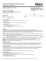
Web-Guard Installation Parts List
Code Name Quantity
A Web-guard 1
B Stainless steel 304 cross
machine screws #8-32*5/8
4
C 304 stainless steel at 4
D 304 stainless steel nut 4
E Nylon at pad cp4 4
Visor installation parts list
Code Name Quantity
F Visor 1
B Stainless steel 304 cross
machine screws #8-32*5/8
2
C 304 stainless steel at 2
D 304 stainless steel nut 2
E Nylon at pad cp4 2
Beauty Plate Installation Parts List
Code Name Quantity
G Beauty plate 1
H Stainless steel 304 cross
machine screws #8-32*1/4
4
Photocell installation parts list
Code Name Quantity
I Photocell 1
Motion sensor installation parts list
Code Name Quantity
J Motion sensor 1
High voltage driver installation parts list
Code Name Quantity
K High voltage drive
347-480V
1
Installation steps:
STEP 1: Open the luminaire by loosening the two screws on the side and safely allowing the glass door to
fall forward on the hinges at its base.
STEP 2: Prepare the back plate for mounting by drilling or knocking out the appropriate holes.
STEP 3: Remove the mounting plate from the back of the luminaire and position on installable surface.
STEP 4: Use the provided 4 screws to securely mount the plate on the desired surface.
STEP 5: If using electrical conduit, remove the screw cap from the desired conduit hole and replace with
conduit. Route the branch circuit wires inside the luminaire. If using a junction box, bring the branch circuit
wires through the rear hole into the luminaire.
STEP 6: Splice the branch circuit power leads to the luminaire power leads, black to black (hot), white to
white (neutral).
STEP 7: Reattach the LED module and driver module to the back plate.
IMPORTANT
STEP 8: Apply caulk between rear of housing and mounting surface to prevent water entry.
A B C D E F
G
H
I J K
Accessories
1. Open the box, remove the luminaire and remove the mounting panel.
2. Per the hole position of the installation panel, a hole is drilled on the installation
surface, and then the fastener is xed on the installation surface through the
installation panel.
3.Wiring before luminaire installation, the zero line is connected to the zero line.
The ground line is grounded, and the live line is connected to the re line
4. According to Figure 4, mount the luminaire directly to the mounting panel.
Open Frame
1. Install the wire guard based on below gure. Using the provided screws and
nuts, secure the wire guard on each side of the luminaire
Wire Guard Installation Instructions
1. 2.
3.
4. 4.
3.

Warranty Information:
This product is warranted for ve years from the date of purchase. If this product does not perform to the specications supplied on this package, send an email or write to the
address below for product return and replacement. This replacement is the sole remedy available. Liability for incidental or consequential damage is expressly excluded.
Visit www.halcolighting.com for full warranty details and compatibility information.
© 2018 Halco Lighting Technologies, LLC. All rights reserved. Halco and ProLED are registered trademarks of Halco Lighting Technologies. All sizes and specications are subject to change. Print Edition 04-15-18
Halco Lighting Technologies | 2940 Pacic Drive | Norcross, GA 30071 | Toll Free 800.677.3334 | Phone 770.242.3612 | Fax 800.880.0822 | halcolighting.com | Atlanta | Cleveland | Houston | Los Angeles | Phoenix
Important Safety Information:
CAUTION: This luminaire must be wired in accordance with the National Electrical Code and applicable local codes andordinances. Proper grounding is
required to insure personal safety. Carefully observe grounding procedure under installation section.
CAUTION: Installation and servicing of this equipment should be performed by qualied personnel only.
CAUTION: Do not mount near gas or electrical heaters.
CAUTION: Equipment should be mounted in locations and at heights where it will not readily be subjected to tampering by unauthorized personnel.
CAUTION: The use of accessory equipment not recommended by the manufacturer may cause an unsafe condition. Any modication or use of non-
original components will void the warranty and product liability.
CAUTION: Do not use this equipment for other than intended use.
CAUTION: Do not install in dead air, sheltered, buried or boxed in location. This luminaire should not be installed in areas that will entrap heat. It is not
intended to be used in potentially dangerous or hazardous locations such as ammable or explosive atmospheres.
CAUTION: This luminaire is not for use with UL924 Emergency Lighting Equipment.
1.Install the Visor as shown in the gure, Screw accrosses at washer
-Visor-Frame-Nylon at washer-put nut on-x Frame
1.Install the Visor as shown in the gure, Screw accrosses at washer
-Visor-Frame-Nylon at washer-put nut on-x Frame
Using at head screw
driver to remove the
waterproof plug head
on the right side of
tting
Using at head screw
driver to remove the
waterproof plug head
on the right side of
tting
Introduce the line of Motion sensor to the inside
of tting and x the cable gland self-contained.
Install the
motion sensor
here
Put the photocell on
the same position, x
the nut from the
external of tting.
Fix the High voltage driver onto the gear plate
1.Install the Visor as shown in the gure, Screw accrosses at washer
-Visor-Frame-Nylon at washer-put nut on-x Frame
Installation Instructions for Visor
Installation Instructions for 347-480V driver
Installation Instructions for Photocell
Installation Instructions for Photocell
Wiring diagram for High voltage driver
Wiring diagram for Photocell
Wiring diagram for Motion Sensor
Installation Instructions for Beauty Plate
Open Frame
Open Frame
Open Frame
/