Page is loading ...

1
®
© 2023 Halco Lighting Technologies, LLC. All rights reserved. Halco and ProLED are registered trademarks of Halco Lighting Technologies. All sizes and specifications are subject to change. Print Edition 070523
Halco Lighting Technologies | 2940 Pacific Drive | Norcross, GA 30071 | Toll Free 800.677.3334 | Phone 770.242.3612 | Fax 800.880.0822 | halcolighting.com | Atlanta | Cleveland | Houston | Phoenix | Chicago
EMG-EXC Installation Instructions
Use Flexible Conduit Only
1. Review the diagrams thoroughly before beginning.
2. All electrical connections must be in accordance with local codes, ordinances, and the National Electric code.
3. Disconnect power at fuse or circuit breaker before installing or servicing.
4. Do not use outdoors.
5. Do not mount in hazardous locations, or near gas or electric heaters.
6. Do not let power cords touch hot surface.
7. Equipment should be mounted in locations and at heights where it will not be subjected to tampering by unauthorized
personnel.
8. The use of accessory equipment not recommend by the manufacturer may cause an unsafe condition.
9. Do not use this equipment for other than intended use.
10. All servicing should be performed by a qualified personnel only.
11. Allow battery to charge for 24 hours before full duration test.
12. Max mouting height: C5U: 24.8ft C5U-RC:25.3ft
SAVE THESE INSTRUCTIONS
Page 1 of 2
PC board
Remote
Connector
head
Remote
White NEUTRAL
Black 120V/AC
Orange 277V/AC
Battery
(option)
Battery
Connect the white wire to neutral.
If using 120V, connect the black wire to the hot lead.
If using 277V, connect the orange wire to the hot lead.
Cap the unused lead.
WIRING DIAGRAM
OPERATION
1. Apply AC power to the unit, the indicator shows red.
2. Push the test switch, the LED indicator turns off and the
LED board stays on .
3. After release the test switch, LED indicator turns back to
red.
TROUBLE SHOOTING GUIDE
If LED board or LED indicator does not illuminate, check the following:
1. Check AC supply - verify that unit has 24 hours AC supply.
2. Battery is not connected.
3. Battery voltage too low- Permit unit to charge for 24 hours then re-test.
4. If above trouble shooting hints do not solve you problem, contact
factory for assistance.
MAINTENANCE
ROUTINE TESTING
National Electric Code (NEC) and NFPA life safety code
regulations require that routine tests need to be performed
as below:
Once every month, perform 30 seconds duration test, push in
and hold the test switch to perform this test. Once every
12 months, perform full 90 minutes test, disconnect AC power
supply and transfer to emergency mode, the unit should stay
on 90 minutes minimum.
Transformer
Lamp
Head
Lamp
Head
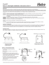
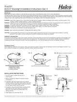
INSTALLATION INSTRUCTIONS
IMPORTANT SAFEGUARDS
READ AND FOLLOW ALL SAFETY INSTRUCTIONS
Always disconnect power at fuse or circuit breaker before installing or servicing, servicing should be performed only by
qualified personnel.
BATTERY: should be tested periodically and replaced when it no longer meet the required duration of 30 second or 90 minutes.
Battery have to recharge if product keep in stock over 9 months, detail manual refer “BATTERY STOCK AND
RECHARGE GUIDELINE”.
Fig 1
Open Front Cover
Slide the switch to another side
for green sign.
The exit sign default setting is red, you can change
to green sign as need.
RED AND GREEN SIGN CHANGEABLE
Fig 2
Remove the red diffuser,
restore green diffuser on the cover.
Red diffuser Green diffuser
Halco Lighting Technologies www.halcolighting.com

2
®
© 2023 Halco Lighting Technologies, LLC. All rights reserved. Halco and ProLED are registered trademarks of Halco Lighting Technologies. All sizes and specifications are subject to change. Print Edition 070523
Halco Lighting Technologies | 2940 Pacific Drive | Norcross, GA 30071 | Toll Free 800.677.3334 | Phone 770.242.3612 | Fax 800.880.0822 | halcolighting.com | Atlanta | Cleveland | Houston | Phoenix | Chicago
EMG-EXC Installation Instructions
J-Box(not included)
Chevron
Frame
Front Cover
Page 2 of 2
Connecting Remote Heads
(see Fig 5)
Connect remote heads extension wire to remote wire, yellow is positive(+),
purple is negative(-). connect wires using wire nuts.
If fixture has remote capability option, Max. remote capability
is 3.6VDC1.5W max.
Ceiling Mounting (see Fig 3)
1. Attach crossbar to junction box, set the crossbar so that the short
blade is touching the J-Box.
2. Open front cover by blade screwdriver.
3. If double face is desired, replace back plate with additional face
plate provided.
4. Remove out the mounting hole cover on the top and side of the
unit, assemble the canopy the unit (see Fig 6).
5. Snap lamp heads on the unit and connect to PC board (see Fig 7).
6. Route the proper wires through mounting hole out of housing.
7. Make electrical connections inside the J-Box as wiring diagram.
8. Fasten crossbar on J-box by screws provided, fasten canopy to
crossbar and against to the wall.
9. Snap chevron to EXIT panel if required.
10. Attach battery connector to PC board, restore front panel on
unit, adjust direction of lamp heads as need.
Canopy Assembly
Put the canopy connector inside
of housing then slider and fixed by
plastic clip.
Fig 3
Fig 4
Ceiling Mounting
Fig 5
Connect Battery And Remote Heads
Fig 7
12
Fig 6
Wall mount
Snap on frame
Lamp Head Assembly
Assemble lamp head on main frame by
plastic clip, lamp head can easy rotate
to frontward or backward.
Canopy
Crossbar
J-Box(not included)
Frame
Lamp Head
Chevron
Front Cover
Remote head
connector
Battery Connector
Lamp Head
Connector
1. Open front cover by blade screwdriver (see Fig 1).
2. Knock out center and appropriate mounting screw holes on the back
plate.
3. Remove side hole plug from housing, snap lamp heads on the unit
and connect to PC board(see Fig 7).
4. Route the AC supply wires through center hole inside of housing.
5. Install fixture on the J-box.
6. Make correct electrical connections inside of fixture according wiring
diagram (see WIRING DIAGRAM) .
7. Push excess wire into J-Box.
8. Snap chevron to EXIT panel if required.
9. Attach battery connector to PC board, restore front panel on unit.
adjust direction of lamp heads as need.
Wall Mounting (see Fig 2)
This product default setting is red exit sign, can change to green
exit sign per need(see Fig 2).
Halco Lighting Technologies www.halcolighting.com
/
