Page is loading ...

IMPORTANT
READ INSTRUCTIONS CAREFULLY BEFORE INSTALLING.
KEEP THESE INSTRUCTIONS FOR FUTURE REFERENCE.
ProLED
®
luminaires must be wired in accordance with the National
Electrical Code and all applicable local codes. Proper grounding is
required for safety.
THIS PRODUCT MUST BE INSTALLED IN ACCORDANCE WITH THE
APPLICABLE INSTALLATION CODE BY A QUALIFIED ELECTRICIAN
WHO IS FAMILIAR WITH THE CONSTRUCTION AND OPERATION
OF THE PRODUCT AND THE HAZARDS INVOLVED.
WARNING - Risk of re or electric shock.
• Turn off electrical power at fuse or circuit breaker box before wiring
luminaire to the power supply.
• Turn off the power when you perform any maintenance.
• Verify that supply voltage is correct by comparing it with the luminaire
label information.
• Make all electrical and grounded connections in accordance with the
National Electrical Code and any applicable local code requirements.
• All wiring connections should be capped with UL approved
wire connectors.
Halco Lighting Technologies | 2940 Pacic Drive | Norcross, GA 30071 | Toll Free 800.677.3334 | Phone 770.242.3612 | Fax 800.880.0822 | halcolighting.com | Atlanta | Carlstadt | Cleveland | Houston | Los Angeles | Phoenix
ProLED
®
Round LED High Bay
Installation Instructions
®
© 2017 Halco Lighting Technologies, LLC. All rights reserved. Halco is a registered trademark of Halco Lighting Technologies. All sizes and specications are subject to change.
CAUTION:
RISK OF INJURY
• Wear gloves and safety glasses at all times when removing luminaire from carton, installing, servicing or
performing maintenance.
• Avoid direct eye exposure to the light source while it is on.
• Account for small parts and destroy packing material, as these may be hazardous to children.
CAUTION:
RISK OF FIRE
• Keep combustible and other materials that can burn away from luminaire and lamp/lens.
• MIN 90°C SUPPLY CONDUCTORS.
IMPORTANT SAFETY INFORMATION:
CAUTION: This luminaire must be wired in accordance with the National Electric Code and applicable local codes and
ordinances. Proper grounding is required for safety.
CAUTION: Installation and servicing of this luminaire should be performed by qualied personnel only.
CAUTION: Do not use this product for other than intended use. To prevent early product failure, luminaire should only be
used in operating environments ranging from -40°C (-40°F) to 40°C (104°F).
Cleaning and Maintenance:
Caution: Do not clean or maintain while the luminaire is energized. Check that the luminaire temperature is cool enough
to touch. Periodically check and remove any accumulated dirt or debris from the lens and around luminaire.
1) Clean lens with non-abrasive glass cleaning solution.
2) Do not open the luminaire to clean the LEDs. Do not touch the LEDs.
Replacement Parts:
Contact your sales representative for replacement part availability or contact Halco Customer Care at 800.677.3334.

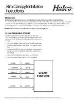
General Wiring Diagram
WARNING:
All units must be individually connected to the AC Supply:
WARNING - All units must be connected to ac power supply:
Select appropriate access point for your installation,remove
knockout, and feed power leads through hole.
Connect the supply wire from the source to the driver.
Black = Line White = Neutral Green = Ground
Consult with dimmer control manufacturer’s wiring instructions.
© 2017 Halco Lighting Technologies, LLC. All rights reserved. Halco is a registered trademark of Halco Lighting Technologies. All sizes and specications are subject to change.
Halco Lighting Technologies | 2940 Pacic Drive | Norcross, GA 30071 | Toll Free 800.677.3334 | Phone 770.242.3612 | Fax 800.880.0822 | halcolighting.com | Atlanta | Carlstadt | Cleveland | Houston | Los Angeles | Phoenix
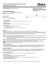
INSTRUCTIONS
Before installation, ensure if power supply is disconnected. Cables must be connected in accordance to instruction and
proper standing rules.
picture 6
picture 7
picture 2
picture 4
picture 1
picture 3
picture 5
Fig. 1
picture 6
picture 7
picture 2
picture 4
picture 1
picture 3
picture 5
Fig. 2
picture 6
picture 7
picture 2
picture 4
picture 1
picture 3
picture 5
Fig. 3
picture 6
picture 7
picture 2
picture 4
picture 1
picture 3
picture 5
Fig. 4
picture 6
picture 7
picture 2
picture 4
picture 1
picture 3
picture 5
Fig. 5
picture 6
picture 7
picture 2
picture 4
picture 1
picture 3
picture 5
Fig. 6
picture 6
picture 7
picture 2
picture 4
picture 1
picture 3
picture 5
Fig. 7
1. To install the reector, unscrew three alternate screws by 5mm, leaving the other three screws untouched, Please
refer to Figure 1.
2. Match the keyholes on reector to the raised screws then rotate reector into position, Please refer to Figure 2.
3. Retighten the raised screws. Don’t overtighten or damage the keyholes or reector, Please refer to Figure 3.
4. Align the junction box to the led driver hole. Note that the box positioning bayonet ribs align with the driver ribs,and
then use of the corresponding hexagonal screw to lock the box on the driver. Please refer to Figure 4.
5. Rotate the top cover of the junction box onto the pipe xed to the ceiling, After tightening, use a screwdriver to install
a setback screw on the NPT collar, Please refer to Figure 5
6. Push the top cover of the tube into the groove on both sides of the junction box. Insulate and connect the electricity
and close the side plates. Please refer to Figure 6.
7. When comes to dimming application, connect the BLUE wire (“+”) to the positive wire “+” of dimmer and white wire
“-” to the negative wire “-” of dimmer, dimmer has 0-10V output, make sure insulation treatment is CORRECT.
8. A listed, liquid-tight, suitable strain relief bushing should be used a outlet box for the power cord.
Warranty Information:
This product is warranted for ve years from the date of purchase.
If this product does not perform to the specications supplied on
this package, send an email or write to the address below for
product return and replacement. This replacement is the sole
remedy available.
Liability for incidental or consequential damage is
expressly excluded.
Visit www.halcolighting.com for full warranty details and
compatibility information.
Operating Characteristic
Voltage input: 120-277V 50/60 Hz
Operating temp: -40°F (-40°C) to 104°F (40°C)
/