Page is loading ...


Copyrights
CY8CKIT-022 CapSense® Liquid Level Sensing Shield Kit Guide, Doc. #: 002-09825 Rev. ** 2
Copyrights
© Cypress Semiconductor Corporation, 2015. The information contained herein is subject to change without notice. Cypress
Semiconductor Corporation assumes no responsibility for the use of any circuitry other than circuitry embodied in a Cypress
product. Nor does it convey or imply any license under patent or other rights. Cypress products are not warranted nor
intended to be used for medical, life support, life saving, critical control or safety applications, unless pursuant to an express
written agreement with Cypress. Furthermore, Cypress does not authorize its products for use as critical components in life-
support systems where a malfunction or failure may reasonably be expected to result in significant injury to the user. The
inclusion of Cypress products in life-support systems application implies that the manufacturer assumes all risk of such use
and in doing so indemnifies Cypress against all charges.
Any Source Code (software and/or firmware) is owned by Cypress Semiconductor Corporation (Cypress) and is protected by
and subject to worldwide patent protection (United States and foreign), United States copyright laws and international treaty
provisions. Cypress hereby grants to licensee a personal, non-exclusive, non-transferable license to copy, use, modify, create
derivative works of, and compile the Cypress Source Code and derivative works for the sole purpose of creating custom
software and or firmware in support of licensee product to be used only in conjunction with a Cypress integrated circuit as
specified in the applicable agreement. Any reproduction, modification, translation, compilation, or representation of this
Source Code except as specified above is prohibited without the express written permission of Cypress.
Disclaimer: CYPRESS MAKES NO WARRANTY OF ANY KIND, EXPRESS OR IMPLIED, WITH REGARD TO THIS
MATERIAL, INCLUDING, BUT NOT LIMITED TO, THE IMPLIED WARRANTIES OF MERCHANTABILITY AND FITNESS
FOR A PARTICULAR PURPOSE. Cypress reserves the right to make changes without further notice to the materials
described herein. Cypress does not assume any liability arising out of the application or use of any product or circuit
described herein. Cypress does not authorize its products for use as critical components in life-support systems where a
malfunction or failure may reasonably be expected to result in significant injury to the user. The inclusion of Cypress’ product
in a life-support systems application implies that the manufacturer assumes all risk of such use and in doing so indemnifies
Cypress against all charges.
Use may be limited by and subject to the applicable Cypress software license agreement.
PSoC and CapSense are registered trademarks and PSoC Creator, F-RAM, EZ-BLE, and PRoC are trademarks of Cypress
Semiconductor Corp. All other trademarks or registered trademarks referenced herein are property of the respective
corporations.
Flash Code Protection
Cypress products meet the specifications contained in their particular Cypress PSoC Data Sheets. Cypress believes that its
family of PSoC products is one of the most secure families of its kind on the market today, regardless of how they are used.
There may be methods, unknown to Cypress, that can breach the code protection features. Any of these methods, to our
knowledge, would be dishonest and possibly illegal. Neither Cypress nor any other semiconductor manufacturer can
guarantee the security of their code. Code protection does not mean that we are guaranteeing the product as ‘unbreakable’.
Cypress is willing to work with the customer who is concerned about the integrity of their code. Code protection is constantly
evolving. We at Cypress are committed to continuously improving the code protection features of our products.

CY8CKIT-022 CapSense® Liquid Level Sensing Shield Kit Guide, Doc. #: 002-09825 Rev. ** 3
Contents
1. Introduction
1.1 Kit Contents.................................................................................................................7
1.2 Getting Started.............................................................................................................8
1.3 Additional Resources...................................................................................................9
1.4 Hardware Requirements..............................................................................................9
1.5 Software Requirements .............................................................................................10
1.5.1 PSoC Creator.................................................................................................10
1.5.2 PSoC Programmer.........................................................................................10
1.6 Application Notes and Projects..................................................................................10
1.7 Technical Support......................................................................................................10
1.8 Documentation Conventions .....................................................................................11
1.9 Acronyms...................................................................................................................11
2. Kit Hardware 12
2.1 Board Details .............................................................................................................12
2.2 Kit Assembly..............................................................................................................15
2.3 Theory of Operation...................................................................................................17
2.3.1 Principle of Capacitive Liquid Level Sensing .................................................17
2.3.2 CY8CKIT-022 Kit............................................................................................18
2.4 Functional Description ...............................................................................................19
2.4.1 Two Sensor Flexible PCB ..............................................................................19
2.4.2 12 Sensor Flexible PCB.................................................................................19
2.4.3 Flexible Sensor Connector.............................................................................20
2.4.4 Arduino-Compatible Headers.........................................................................20
2.4.5 Temperature Compensation Sensor ..............................................................22
2.4.6 Integration Capacitors....................................................................................22
2.4.7 UART Connection..........................................................................................23
2.4.8 Liquid Container.............................................................................................23
3. Example Projects 24
4. Design Support 25
A. Appendix 26
A.1 Shield Schematic.......................................................................................................26
A.2 2RX Sensor Schematic..............................................................................................27
A.3 12RX Sensor Schematic............................................................................................28
A.4 Shield Layout.............................................................................................................29
A.5 2RX Sensor Layout....................................................................................................30
A.6 12RX Sensor Layout..................................................................................................31
A.7 Bill of Materials ..........................................................................................................32


CY8CKIT-022 CapSense® Liquid Level Sensing Shield Kit Guide, Doc. #: 002-09825 Rev. ** 5
Safety Information
Regulatory Compliance
The CapSense Liquid Level Sensing Shield Kit (CY8CKIT-022) is intended for use as a development
platform for hardware or software in a laboratory environment. The board is an open system design,
which does not include a shielded enclosure. This may cause interference to other electrical or
electronic devices in close proximity. In a domestic environment, this product may cause radio
interference. In such cases, you may be required to take adequate preventive measures. In addition,
this board should not be used near any medical equipment or RF devices.
Attaching additional wiring to this product or modifying the product operation from the factory default
may affect its performance and cause interference with other apparatus in the immediate vicinity. If
such interference is detected, suitable mitigating measures should be taken.
The Liquid Level Sensing Shield Kit, as shipped from the factory, has been verified to meet with the
requirements of CE as a Class A product.
The Liquid Level Sensing Shield Kit contains ESD-sensitive
devices. Electrostatic charges readily accumulate on the
human body and any equipment, and can discharge without
detection. Permanent damage may occur on devices
subjected to high-energy discharges. Proper ESD
precautions are recommended to avoid performance
degradation or loss of functionality. Store unused kit boards
in the protective shipping package.
End-of-Life/Product Recycling
This kit has an end-of life five years from the date of
manufacture mentioned on the back of the box. Contact your
nearest recycler for discarding the kit.

CY8CKIT-022 CapSense® Liquid Level Sensing Shield Kit Guide, Doc. #: 002-09825 Rev. ** 6
General Safety Instructions
ESD Protection
ESD can damage boards and associated components. Cypress recommends that you perform
procedures only at an ESD workstation. If such a workstation is not available, use appropriate ESD
protection by wearing an antistatic wrist strap attached to the chassis ground (any unpainted metal
surface) on your board when handling parts.
Handling Boards
CY8CKIT-022 boards are sensitive to ESD. Hold the board only by its edges. Do not slide the board
over any surface.

CY8CKIT-022 CapSense® Liquid Level Sensing Shield Kit Guide, Doc. #: 002-09825 Rev. ** 7
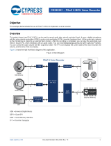
Thank you for your interest in the CapSense
®
Liquid Level Sensing Shield Kit (CY8CKIT-022). This
kit is intended to demonstrate the Liquid Level Sensing (LLS) capabilities of the CapSense technol-
ogy in Cypress’s PSoC
®
4 products.
This kit supports the following liquid level sensing features:
■ Non-contact measurement of liquid levels from sensors located on the exterior of the non-
conductive liquid container. Avoids contamination and cleaning issues found with mechanical and
contact sensors, simplifying industrial design and improving user experience.
■ Supports two different sensor patterns. A two sensor ‘Backgammon’ shaped pattern provides
liquid level sensing at a low cost point while a multi sensor ‘Segmented’ pattern provides
increased accuracy that can be optimized for each design by varying the number and shape of
sensors.
This kit guide provides details on the kit contents, hardware, schematics, and BOM. See Code
Example CE202479 for example projects developed for use with this kit and
AN202478 - PSoC 4 - Capacitive Liquid Level Sensing for theory, design guidance, and sensor
layout information.
1.1 Kit Contents
The CapSense Liquid Level Sensing Shield Kit contains the following, as shown in Figure 1-1.
■ CapSense
®
Liquid Level Sensing Shield board
■ CapSense Liquid Level Sensing 12 Sensor Flex PCB
■ CapSense Liquid Level Sensing 2 Sensor Flex PCB
■ Liquid container
■ Quick Start Guide
■ Micrium's C/Probe license card
1. Introduction

CY8CKIT-022 CapSense® Liquid Level Sensing Shield Kit Guide, Doc. #: 002-09825 Rev. ** 8
Introduction
Figure 1-1. Kit Contents
Inspect the contents of the kit; if you find any part missing, contact your nearest Cypress sales office
for help.
1.2 Getting Started
This guide will help you get acquainted with the CapSense Liquid Level Sensing Shield Kit:
■ The Kit Hardware chapter on page 12 describes how to assemble and use the kit’s resources.
■ The Example Projects chapter on page 24 provides the major features of the Liquid Level
Sensing Shield Kit.
■ The Design Support chapter on page 25 provides information on documents and resources
required to start new liquid level sensing desings with PSoC 4 CapSense.
■ The Appendix on page 26 provides detailed hardware description, schematics, and bill of
materials (BOM).

CY8CKIT-022 CapSense® Liquid Level Sensing Shield Kit Guide, Doc. #: 002-09825 Rev. ** 9
Introduction
1.3 Additional Resources
Cypress provides a wealth of data at www.cypress.com to help you select the right PSoC device for
your design, and to help you to quickly and effectively integrate the device into your design. For a
comprehensive list of resources, visit http://www.cypress.com/psoc. The web page includes a list of
PSoC device families, integrated design environments (IDEs), and associated development kits. In
addition, refer to the following documents to get started with PSoC 4 devices and CapSense
technology:
■ AN79953 - Getting Started with PSoC® 4
■ Getting Started with CapSense®
■ PSoC® 4 CapSense® Design Guide
■ AN202478 - PSoC 4 - Capacitive Liquid Level Sensing
■ CE202479 - Code Example for Liquid Level Sensing
■ PSoC 101 Training Series
1.4 Hardware Requirements
CY8CKIT-022 plugs into any Arduino™ hardware-compatible development platform from Cypress.
CE202479 provides example projects targeting the CY8CKIT-042 PSoC 4 Pioneer Kit.
Figure 1-2 shows how the CY8CKIT-022 kit connects to the CY8CKIT-042 kit.
Visit http://www.cypress.com/CY8CKIT-042 to purchase the CY8CKIT-042 kit.
Figure 1-2. CY8CKIT-022 Connected to CY8CKIT-042

CY8CKIT-022 CapSense® Liquid Level Sensing Shield Kit Guide, Doc. #: 002-09825 Rev. ** 10
Introduction
1.5 Software Requirements
The CY8CKIT-022 kit does not have any programmable/configurable devices onboard, so it does not
need any software for configuration. However, the PSoC device present on the CY8CKIT-042
baseboard requires firmware which you can develop with the PSoC Creator IDE (Version 3.3 CP1 or
later).
1.5.1 PSoC Creator
PSoC Creator allows concurrent hardware and application firmware design of PSoC 3, PSoC 4, and
PSoC 5LP systems. PSoC systems are designed using classic, familiar, schematic-capture technol-
ogy supported by pre-verified, production-ready PSoC Components™.
PSoC Components are analog and digital virtual chips represented by icons that you can drag and
drop into a design and configure to suit a broad array of application requirements. You can configure
each Component in the rich, mixed-signal Cypress Component Catalog with the Component Cus-
tomizer tool. These Components include a full set of dynamically generated API libraries. After you
have configured the PSoC system, you can write, compile, and debug the firmware within PSoC
Creator, or export the firmware to other IDEs such as those from IAR, Keil, and Eclipse.
You can download the latest version of the PSoC Creator software from http://www.cypress.com/
psoccreator. Refer to the Release Notes for the minimum and recommended system requirements.
1.5.2 PSoC Programmer
The PSoC Programmer software is used to program the PSoC devices on the CY8CKIT-042 kit with
hex files. You can download PSoC Programmer at http://www.cypress.com/go/psocprogrammer.
1.6 Application Notes and Projects
■ AN202478 - PSoC 4 - Capacitive Liquid Level Sensing provides detailed theory, design
guidance, and sensor layout information for explaining this kits operation as well as developing a
new liquid level sensing design.
■ CE202479 contains example projects that demonstrate the following features of the
CY8CKIT-022 kit:
❐ Liquid level measurement using capacitive sensors
❐ Two sensor (2RX) project for use with the low cost 2RX flexible sensor
❐ Twelve sensor (12RX) project for use with the increased accuracy 12RX flexible sensor
❐ See the 3. Example Projects chapter in this kit guide for details.
1.7 Technical Support
For assistance, visit Cypress Support or contact customer support at +1 (800) 541-4736 Ext. 2 (in
the USA) or +1 (408) 943-2600 Ext. 2 (International).
You can also use the following support resources if you need quick assistance:
■ Self-help (Technical Documents)
■ Local Sales Office Locations.

CY8CKIT-022 CapSense® Liquid Level Sensing Shield Kit Guide, Doc. #: 002-09825 Rev. ** 11
Introduction
1.8 Documentation Conventions
1.9 Acronyms
Table 1-1. Document Conventions for Guides
Convention Usage
Courier New
Displays file locations, user entered text, and source code:
C:\ ...cd\icc\
Italics
Displays file names and reference documentation:
Read about the sourcefile.hex file in the PSoC Designer User Guide.
[Bracketed, Bold]
Displays keyboard commands in procedures:
[Enter] or [Ctrl] [C]
File > Open
Represents menu paths:
File > Open > New Project
Bold
Displays commands, menu paths, and icon names in procedures:
Click the File icon and then click Open.
Times New Roman
Displays an equation:
2 + 2 = 4
Text in gray boxes Describes Cautions or unique functionality of the product.
Table 1-2. Acronyms Used in the Document
Acronym Description
LLS Liquid Level Sensing
C
L
Liquid Capacitance
C
P
Parasitic Capacitance
GND Ground
IDE Integrated Design Environment
PCB Printed Circuit Board
IO Input Output Pin
USB Universal Serial Bus
UART Universal Asynchronous Receiver/Transmitter
PET Polyethylene Terephthalate

CY8CKIT-022 CapSense® Liquid Level Sensing Shield Kit Guide, Doc. #: 002-09825 Rev. ** 12
2. Kit Hardware
2.1 Board Details
The CY8CKIT-022 kit contains the following components:
■ CapSense
®
Liquid Level Sensing Shield board
❐ Arduino-compatible headers to interface the Cypress PSoC 4 Pioneer Kit pins to the flexible
liquid sensor connector pins
❐ Connects PSoC 4 Pioneer UART pins to Pioneer KitProg UART pins
❐ Optional temperature compensation sensor
■ CapSense Liquid Level Sensing 2 Sensor Flex PCB
❐ Low cost design provides two sensors (RX0, RX1) for liquid level measurement and a ground
plane (TX0) to improve signal uniformity
■ CapSense Liquid Level Sensing 12 Sensor Flex PCB
❐ Higher accuracy design provides 12 sensors (RX[0:11]) for liquid measurement
Figure 2-1 through Figure 2-4 show the top and bottom views of the CY8CKIT-022 board.
Figure 2-1. CY8CKIT-022 Shield Board (Top View)

CY8CKIT-022 CapSense® Liquid Level Sensing Shield Kit Guide, Doc. #: 002-09825 Rev. ** 13
Kit Hardware
Figure 2-2. CY8CKIT-022 Shield Board (Bottom View)
Figure 2-3. Top View of both CY8CKIT-022 Sensors

CY8CKIT-022 CapSense® Liquid Level Sensing Shield Kit Guide, Doc. #: 002-09825 Rev. ** 14
Kit Hardware
Figure 2-4. Bottom View of both CY8CKIT-022 Sensors

CY8CKIT-022 CapSense® Liquid Level Sensing Shield Kit Guide, Doc. #: 002-09825 Rev. ** 15
Kit Hardware
2.2 Kit Assembly
Follow these assembly steps to operate the kit:
1. Remove the adhesive sticker from the back of one of the CapSense Liquid Level Sensor Flex
PCB and then paste the sensor onto the liquid container, as shown in Figure 2-5. Center the sen-
sor on one of the flat sides so the top of the sensor is aligned with the top of the flat section. This
placement will result in the 0 mm (0%) line on the sensor being approximately 15 mm from the
bottom of the container.
Note If the sensor flex is placed too low on the container, the radius of bend on the flex tail may
cause the container to become unstable.
Figure 2-5. Placing the Sensor
2. Thoroughly press the entire sensor area to the container to ensure there are no air bubbles in the
adhesive layer. Air bubbles allow the distance between the sensor and the liquid to fluctuate.
Distance changes cause changes to the sensor’s capacitance resulting in reduced liquid level
accuracy. Air bubbles can be observed through the adhesive layer on the back of the sensor
through the bottle.
3. Connect the CapSense Liquid Level Sensing Shield onto the CY8CKIT-042 PSoC 4 Pioneer Kit
Arduino header, as shown in Figure 2-6, and confirm if the PSoC 4 Pioneers kits jumpers are in
default positions.

CY8CKIT-022 CapSense® Liquid Level Sensing Shield Kit Guide, Doc. #: 002-09825 Rev. ** 16
Kit Hardware
Figure 2-6. Kit Connections
4. Connect the CapSense Liquid Level Sensing Flex PCB to the CapSense Liquid Level Sensing
Shield.
5. Connect the CY8CKIT-042 to your PC using the provided USB cable.
6. Compatible firmware and operating instructions are provided in code example CE202479.

CY8CKIT-022 CapSense® Liquid Level Sensing Shield Kit Guide, Doc. #: 002-09825 Rev. ** 17
Kit Hardware
2.3 Theory of Operation
For a detailed explanation on the theory of operation of this kit, refer to AN202478 - PSoC 4 -
Capacitive Liquid Level Sensing.
This section provides a high-level description of the principle of capacitive sensing and describes
where the CY8CKIT-022 kit and PSoC devices fit in a capacitive liquid level sensing system.
2.3.1 Principle of Capacitive Liquid Level Sensing
Capacitive liquid level sensors are conductive pads or traces laid on non-conductive material such
as PCB, plastic, or glass. The intrinsic capacitance of the PCB trace, pads, and other connections to
the sensor results in a sensor parasitic capacitance (C
P
). When a capacitive sensor is excited by a
voltage source, an electric field is created around the sensor. A small number of electric field lines
couple with the nearby ground, while most of the electric field lines are projected into the nearby
space of the liquid container, as shown in Figure 2-7.
When a target object such as water approaches the sensor, the electric field couples with it and adds
small amount of liquid capacitance (C
L
) to the existing C
P
, as shown in Figure 2-8. The capacitive
liquid level sensing technique involves measuring this change in the capacitance of a sensor when
water is near the sensor.
Figure 2-7. Capacitance and Electric Field of a Capacitive Liquid Level Sensor
Figure 2-8. Added Capacitance (C
L
) When Liquid Approaches a Capacitive Sensor
PCB
Ground
Ground
C
P
C
P
Container Wall
Liquid
Sensor
PCB
Ground Ground
C
P
C
P
Container Wall
Liquid
Sensor
C
L

CY8CKIT-022 CapSense® Liquid Level Sensing Shield Kit Guide, Doc. #: 002-09825 Rev. ** 18
Kit Hardware
2.3.2 CY8CKIT-022 Kit
The CY8CKIT-022 kit contains capacitive sensors attached to a liquid container. These sensors can
be interfaced with PSoC 4 devices present on Cypress PSoC 4 Pioneer Kits through Arduino-
compatible headers, as shown in Figure 2-9.
Figure 2-9. CY8CKIT-022 System Block Diagram
In the CY8CKIT-022 system, the CapSense circuitry in the PSoC device on the baseboard (such as
CY8CKIT-042) senses the changes in the capacitance of the liquid level sensors on the
CY8CKIT-022 kit. The PSoC calculates the liquid level based on the information about capacitance
changes on different sensors received from the CapSense block.
You can program the PSoC device on the baseboard through the onboard KitProg hardware, which
communicates to the software programming tool (PSoC Programmer) through the USB interface on
the board. You can develop firmware applications for PSoC 4 devices by using PSoC Creator.
CE202479 provides code example projects that you can use with the CY8CKIT-022 system to
implement liquid level sensing solutions.

CY8CKIT-022 CapSense® Liquid Level Sensing Shield Kit Guide, Doc. #: 002-09825 Rev. ** 19
Kit Hardware
2.4 Functional Description
2.4.1 Two Sensor Flexible PCB
The signal ratio from the two sensors (RX0 and RX1) provides a low cost method of determining
liquid height. The pattern shown in Figure 2-10 is similar to a backgammon game board, and is
therefore referred to as the “backgammon” pattern. A third transmitter (TX0) sensor is provided to
support the CapSense mutual capacitance scanning method, and can be connected as a CapSense
transmitter. If CapSense self capacitance scanning is used, then the TX0 sensor is not required and
must be grounded to avoid interfering with the RX0 and RX1 sensors. The flexible PCB comes with
a non-conductive double sided adhesive already applied. To use the sensor, it must be adhered to
the flat side of the supplied liquid container and attached to the kit shield board.
Figure 2-10. 2RX Sensor Pattern
2.4.2 12 Sensor Flexible PCB
Each segment of the 12 sensor (RX[0:11]) pattern shown in Figure 2-11 provides an incremental
portion of the total liquid level. While the “segmented” pattern requires additional sensor elements
and pin compared to the 2RX version, it allows liquid level resolution to be customized for each
design. For use with CapSense self capacitance scanning, only the sensors RX[0:11] must be
connected to the PSoC CapSense I/O pins and the TX0 sensor can be left floating or tied to ground.
When CapSense mutual capacitance scanning is used, all of the RX and TX sensors must be
connected. A small ground plane hatch between the RX and TX sensors is provided to help direct
the electrical field into the liquid to increase sensitivity.
Figure 2-11. 12RX Sensor Pattern

CY8CKIT-022 CapSense® Liquid Level Sensing Shield Kit Guide, Doc. #: 002-09825 Rev. ** 20
Kit Hardware
2.4.3 Flexible Sensor Connector
Connector (J5) allows easy connection of sensors to the PSoC on the Pioneer kit. The connector
shown in Figure 2-12 provides connection of up to 13 sensors (RX[0:12]). A single transmitter
connection (TX0) is provided for use with sensors utilizing the CapSense Mutual-Capacitance Scan
method. The TX0 signal includes a 470 series resistor to slow edge rates and reduce radiated
emissions. The connector can be used with the kit supplied sensors or a custom user created
sensor.
Figure 2-12. Sensor Connector
2.4.4 Arduino-Compatible Headers
The I/O headers (J1-J4) comply with the Arduino™ UNO (R3) kit form-factor to support similar form-
factor baseboards, as provided in Table 2-1 through Table 2-4.
Table 2-1. J1 Arduino Header or Power Connector
Pin Arduino Board Signal CY8CKIT-022 CY8CKIT-042
J1.1 VIN
VIN
J1.2 GND GND GND
J1.3 GND GND GND
J1.4 V5.0
V5.0
J1.5 V3.3
V3.3
J1.6 RESET
RESET
J1.7 IOREF
P4.VDD
J1.8 NC
/