Page is loading ...


Copyrights
CY8CKIT-026 CAN and LIN Shield Kit Guide, Doc. No. 002-03798 Rev. *C 2
Copyrights
© Cypress Semiconductor Corporation, 2015-2017. This document is the property of Cypress Semiconductor Corporation
and its subsidiaries, including Spansion LLC ("Cypress"). This document, including any software or firmware included or ref-
erenced in this document ("Software"), is owned by Cypress under the intellectual property laws and treaties of the United
States and other countries worldwide. Cypress reserves all rights under such laws and treaties and does not, except as spe-
cifically stated in this paragraph, grant any license under its patents, copyrights, trademarks, or other intellectual property
rights. If the Software is not accompanied by a license agreement and you do not otherwise have a written agreement with
Cypress governing the use of the Software, then Cypress hereby grants you a personal, non-exclusive, nontransferable
license (without the right to sublicense) (1) under its copyright rights in the Software (a) for Software provided in source code
form, to modify and reproduce the Software solely for use with Cypress hardware products, only internally within your organi-
zation, and (b) to distribute the Software in binary code form externally to end users (either directly or indirectly through resell-
ers and distributors), solely for use on Cypress hardware product units, and (2) under those claims of Cypress's patents that
are infringed by the Software (as provided by Cypress, unmodified) to make, use, distribute, and import the Software solely
for use with Cypress hardware products. Any other use, reproduction, modification, translation, or compilation of the Software
is prohibited.
TO THE EXTENT PERMITTED BY APPLICABLE LAW, CYPRESS MAKES NO WARRANTY OF ANY KIND, EXPRESS OR
IMPLIED, WITH REGARD TO THIS DOCUMENT OR ANY SOFTWARE OR ACCOMPANYING HARDWARE, INCLUDING,
BUT NOT LIMITED TO, THE IMPLIED WARRANTIES OF MERCHANTABILITY AND FITNESS FOR A PARTICULAR PUR-
POSE. To the extent permitted by applicable law, Cypress reserves the right to make changes to this document without fur-
ther notice. Cypress does not assume any liability arising out of the application or use of any product or circuit described in
this document. Any information provided in this document, including any sample design information or programming code, is
provided only for reference purposes. It is the responsibility of the user of this document to properly design, program, and test
the functionality and safety of any application made of this information and any resulting product. Cypress products are not
designed, intended, or authorized for use as critical components in systems designed or intended for the operation of weap-
ons, weapons systems, nuclear installations, life-support devices or systems, other medical devices or systems (including
resuscitation equipment and surgical implants), pollution control or hazardous substances management, or other uses where
the failure of the device or system could cause personal injury, death, or property damage ("Unintended Uses"). A critical
component is any component of a device or system whose failure to perform can be reasonably expected to cause the failure
of the device or system, or to affect its safety or effectiveness. Cypress is not liable, in whole or in part, and you shall and
hereby do release Cypress from any claim, damage, or other liability arising from or related to all Unintended Uses of Cypress
products. You shall indemnify and hold Cypress harmless from and against all claims, costs, damages, and other liabilities,
including claims for personal injury or death, arising from or related to any Unintended Uses of Cypress products.
Cypress, the Cypress logo, Spansion, the Spansion logo, and combinations thereof, WICED, PSoC, CapSense, EZ-USB, F-
RAM, and Traveo are trademarks or registered trademarks of Cypress in the United States and other countries. For a more
complete list of Cypress trademarks, visit cypress.com. Other names and brands may be claimed as property of their respec-
tive owners.

CY8CKIT-026 CAN and LIN Shield Kit Guide, Doc. No. 002-03798 Rev. *C 3
1. Introduction 6
1.1 Kit Contents.................................................................................................................6
1.2 Getting Started.............................................................................................................7
1.3 Additional Learning Resources....................................................................................9
1.4 Technical Support......................................................................................................10
1.5 Acronyms...................................................................................................................10
1.6 Document Conventions .............................................................................................10
2. Installation 11
2.1 Before You Begin.......................................................................................................11
2.2 Install Software ..........................................................................................................12
2.3 Uninstall Software......................................................................................................14
2.4 Install Hardware.........................................................................................................14
3. Hardware 15
3.1 System Block Diagram ..............................................................................................15
3.2 CAN Physical Layer Transceiver Circuits..................................................................17
3.3 LIN Physical Layer Transceiver Circuits....................................................................20
3.4 Status LEDs...............................................................................................................22
3.5 Port Options with CY8CKIT-042/044 Pioneer Kit ......................................................23
3.6 Power Supply Configurations ....................................................................................24
4. Kit Operation 30
4.1 Default Jumper Settings on CY8CKIT-026................................................................30
4.2 CAN Communication Hardware Setup ......................................................................30
4.3 Using CAN Bus Analyzer Tool...................................................................................32
4.4 LIN Communication Hardware Setup ........................................................................34
4.5 Using LIN Bus Analyzer Tool.....................................................................................35
5. Example Projects 37
5.1 Using the Kit Example Projects .................................................................................37
5.2 CAN_Simplex_Tx_CY8CKIT-044..............................................................................38
5.3 CAN_Simplex_Rx_CY8CKIT-044..............................................................................41
5.4 LIN_Slave_CY8CKIT-042..........................................................................................45
5.5 LIN_Slave_CY8CKIT-044..........................................................................................49
5.6 Multiple_LIN_Slave_CY8CKIT-042 ...........................................................................49
Appendix 54
Schematics 54
Gerber Files 58
Bill of Materials 62
Contents

CY8CKIT-026 CAN and LIN Shield Kit Guide, Doc. No. 002-03798 Rev. *C 4
Safety Information
Regulatory Compliance
The CY8CKIT-026 CAN and LIN Shield Kit is intended for use as a development platform for
hardware or software in a laboratory environment. The board is an open system design, which does
not include a shielded enclosure. This may cause interference to other electrical or electronic
devices in close proximity. In a domestic environment, this product may cause radio interference. In
such cases, you may be required to take adequate preventive measures. In addition, this board
should not be used near any medical equipment or RF devices.
Attaching additional wiring to this product or modifying the product operation from the factory default
may affect its performance and cause interference with other apparatus in the immediate vicinity. If
such interference is detected, suitable mitigating measures should be taken.
The CAN and LIN Shield Kit, as shipped from the factory, has been verified to meet with the
requirements of CE as a Class A product.
The CAN and LIN Shield Kit contains ESD-sensitive
devices. Electrostatic charges readily accumulate on the
human body and any equipment, and can discharge without
detection. Permanent damage may occur on devices
subjected to high-energy discharges. Proper ESD
precautions are recommended to avoid performance
degradation or loss of functionality. Store unused kit boards
in the protective shipping package.
End-of-Life/Product Recycling
This kit has an end-of life five years from the date of
manufacture mentioned on the back of the box. Contact your
nearest recycler for discarding the kit.

CY8CKIT-026 CAN and LIN Shield Kit Guide, Doc. No. 002-03798 Rev. *C 5
General Safety Instructions
ESD Protection
ESD can damage boards and associated components. Cypress recommends that you perform
procedures only at an ESD workstation. If such a workstation is not available, use appropriate ESD
protection by wearing an antistatic wrist strap attached to the chassis ground (any unpainted metal
surface) on your board when handling parts.
Handling Boards
CAN and LIN Shield Kit boards are sensitive to ESD. Hold the board only by its edges. After
removing the board from its box, place it on a grounded, static-free surface. Use a conductive foam
pad if available. Do not slide the board over any surface.

CY8CKIT-026 CAN and LIN Shield Kit Guide, Doc. No. 002-03798 Rev. *C 6
1. Introduction
Thank you for your interest in the CY8CKIT-026 CAN and LIN Shield Kit. This kit is intended to
demonstrate the CAN and LIN bus communications in Cypress’s PSoC
®
products.
The CY8CKIT-026 CAN and LIN Shield Kit is an Arduino compatible shield board that is used with
several Cypress kits such as the CY8CKIT-042 PSoC 4 Pioneer Kit/CY8CKIT-044 PSoC 4 M-Series
Pioneer Kit or FM4-176L-S6E2GM - ARM
®
Cortex
®
-M4 MCU Pioneer Kit. It enables you to evaluate
the Controller Area Network (CAN) and Local Interconnect Network (LIN) slave communication
capability of Cypress devices. You can design your own projects with easy-to-use CAN and LIN
slave components in Cypress’s PSoC Creator™ software, or by altering code examples provided
with this kit.
This kit guide provides details on the kit contents, hardware, example projects, schematics, and
BOM.
1.1 Kit Contents
The CY8CKIT-026 CAN and LIN Shield Kit contains the following, as shown in Figure 1-1:
■ CAN and LIN Shield Board
■ Three jumper wires (5 inches each)
■ Three jumper wires (4 inches each)
■ Four connectors (one 10 × 1, two 8 × 1 and one 6 × 1)
■ Quick Start Guide
Figure 1-1. CY8CKIT-026 CAN and LIN Shield Kit

CY8CKIT-026 CAN and LIN Shield Kit Guide, Doc. No. 002-03798 Rev. *C 7
Introduction
Inspect the contents of the kit; if anything is missing, contact your nearest Cypress sales office for
assistance. Go to www.cypress.com/support for more information on Cypress sales offices and
support.
1.1.1 Kit Compatibility
This kit contains an Arduino compatible shield board and requires other Cypress kits (Ardunio
compatible) to use it. It is designed to add CAN and LIN capabilities to the PSoC 4 Series Pioneer
Kits (CY8CKIT-042/44) and FM4 kits such as FM4-176L-S6E2GM - ARM Cortex-M4 MCU Pioneer
Kit.
This kit is also compatible with any other general Arduino compatible Kit which supports CAN/LIN
protocol.
CAN and LIN are communication protocols and require more than one CAN or LIN node to set up
communication between nodes. Therefore, it is recommended to have two CY8CKIT-044 Pioneer
Kits or other compatible kits and two CY8CKIT-026 CAN and LIN Shield Kits. This enables you to set
up CAN communication between two CAN nodes. An alternative recommendation is to have a CAN
or LIN bus emulator or analyzer. This enables you to emulate a CAN or LIN node to communicate
with the PSoC CAN or LIN controller. See sections Using CAN Bus Analyzer Tool on page 32 and
Using LIN Bus Analyzer Tool on page 35 for more details on using a CAN analyzer or LIN analyzer
tool with this kit.
For detailed information about the differences between PSoC 4 devices, go to
www.cypress.com/psoc. For more information about Cypress kits, go to the Cypress Store at
www.cypress.com/shop.
1.2 Getting Started
This guide will help you to get acquainted with the CY8CKIT-026 CAN and LIN Shield Kit:
■ The Installation chapter on page 11 describes the installation of the kit software. This includes the
PSoC Creator IDE to develop and debug the applications, and PSoC Programmer to program the
.hex files on to the device.
■ The Hardware chapter on page 15 details the hardware content of the kit and the hardware
operation.
■ The Kit Operation chapter on page 30 explains you on how to set-up the hardware connections in
order to establish CAN and LIN communication using CY8CKIT-026.
■ The Example Projects chapter on page 37 describes code examples that will help you
understand how to create your own CAN and LIN communication projects on PSoC 4.
■ The Appendix chapter on page 54 provides schematics, layout and the bill of materials (BOM).
Refer to the kit web page for the latest information on using this kit with various Cypress devices.
The web page will be updated as new devices and development kits compatible with this shield are
released to the market.

CY8CKIT-026 CAN and LIN Shield Kit Guide, Doc. No. 002-03798 Rev. *C 8
Introduction
1.2.1 Beginner Resources
An overview of PSoC devices is available at www.cypress.com/psoc. The web page includes a list of
PSoC device families, integrated design environments (IDEs), and associated development kits. In
addition, refer to the following documents to get started with PSoC 4 devices and CAN/LIN
communication:
■ AN79953 - Getting Started with PSoC® 4.
■ CE97311 - PSoC® 4 M: CAN Simplex Communication with CapSense®.
■ CE96999 - Basic LIN Slave Implementation in PSoC® 4.
■ PSoC Creator 101 Training Series.
■ CE211027 - CAN Communication between FM4-S6E2Gx Series and PSoC® 4 M-Series using
the CY8CKIT-026 CAN and LIN Shield Kit.
1.2.2 Hardware Requirements
CY8CKIT-026 plugs into any Arduino™ hardware-compatible development platforms from Cypress.
This Kit provides example projects targeting the CY8CKIT-042 PSoC 4 Pioneer Kit and
CY8CKIT-044 PSoC 4 M-Series Pioneer Kit. For FM4 Kit CAN example project and hardware
connections, please refer to the Code Example CE211027 - CAN Communication between
FM4-S6E2Gx Series and PSoC® 4 M-Series using the CY8CKIT-026 CAN and LIN Shield Kit.
Figure 1-2 shows how the CY8CKIT-026 Kit connects to the CY8CKIT-044 Kit.
Figure 1-2. CY8CKIT-026 Connected to CY8CKIT-044
You can purchase the CY8CKIT-042 kit from www.cypress.com/CY8CKIT-042 and
the CY8CKIT-044 kit from www.cypress.com/CY8CKIT-044.
1.2.3 Software Requirements
The CY8CKIT-026 kit does not have any programmable/configurable device onboard, so it does not
need any software for configuration. However, the PSoC device present on baseboards, such as
CY8CKIT-042 or CY8CKIT-044, requires firmware, which you can develop with the PSoC Creator
IDE (Version 3.3 SP1 or later).

CY8CKIT-026 CAN and LIN Shield Kit Guide, Doc. No. 002-03798 Rev. *C 9
Introduction
1.2.3.1 PSoC Creator
PSoC Creator allows concurrent hardware and application firmware design of PSoC 3, PSoC 4, and
PSoC 5LP systems. PSoC systems are designed using classic, familiar, schematic-capture
technology supported by pre-verified, production ready PSoC Components™.
PSoC Components are analog and digital virtual chips represented by icons that you can drag and
drop into a design and configure to suit a broad array of application requirements. You can configure
each Component in the rich, mixed-signal Cypress Component Catalog with the Component
Customizer tool. These Components include a full set of dynamically generated API libraries. After
you have configured the PSoC system, you can write, compile, and debug the firmware within PSoC
Creator, or export the firmware to other IDEs such as those from IAR, Keil, and Eclipse.
You can download the latest version of the PSoC Creator software from www.cypress.com/
psoccreator. Refer to the Release Notes for the minimum and recommended system requirements.
1.2.3.2 PSoC Programmer
The PSoC Programmer software is used to program the PSoC 4 devices on the CY8CKIT-042 kit
and CY8CKIT-044 kit with hex files. PSoC Programmer is installed along with PSoC Creator. You
can also download PSoC Programmer separately at www.cypress.com/psocprogrammer.
1.3 Additional Learning Resources
Visit www.cypress.com for additional learning resources in the form of datasheets, technical
reference manuals, and application notes.
Code Example CE97311 describes the implementation of CAN bus communication between two
PSoC 4 devices. It explains how to send and receive CAN messages. It has two example projects
which describe how to transmit/receive CAN messages using the CAN and LIN Shield Kit and
CY8CKIT-044 PSoC 4 M-Series Pioneer Kit.
Code Example CE96999 describes the implementation of LIN bus communication using PSoC. It
explains how to send and receive LIN messages. It has two example projects which describe how to
transmit/receive LIN messages using the CAN and LIN Shield Kit and CY8CKIT-042/CY8CKIT-044
PSoC 4 Pioneer Kits.
Code Example CE211027 describes the implementation of CAN bus communication between
FM4-S6E2Gx Series and PSoC 4 M-Series. FM4 acts as Transmitter and PSoC 4 M acts as a
receiver which changes the RGB LED color based on the commands received from the FM4.

CY8CKIT-026 CAN and LIN Shield Kit Guide, Doc. No. 002-03798 Rev. *C 10
Introduction
1.4 Technical Support
For assistance, go to our support web page (www.cypress.com/support) or contact our customer
support at +1(800) 541-4736 Ext. 2 (in the USA), or +1 (408) 943-2600 Ext. 2 (International).
1.5 Acronyms
1.6 Document Conventions
Table 1-1. Acronyms
Acronym Definition
BOM Bill of Materials
CAN
Controlled Area Network
DLC Data Length Code
IDE
Integrated Design Environment
LIN
Local Interconnect Network
USB Universal Serial Bus
Table 1-2. Document Convention for Guides
Acronym Definition
Courier New
Displays file locations, user entered text, and source code:
C:\...cd\icc\
Italics
Displays file names and reference documentation:
Read about the sourcefile.hex file in the PSoC Creator User Guide
[Bracketed, Bold]
Displays keyboard commands in procedures:
[Enter] or [Ctrl] [C]
File > Open
Represents menu paths:
File > Open > New Project
Bold
Displays commands, menu paths, and icon names in procedures: Click the File icon
and then click Open.
Times New Roman
Displays an equation:
2 + 2 = 4
Text in gray boxes
Describe s Cautions or unique functionality of the product.

CY8CKIT-026 CAN and LIN Shield Kit Guide, Doc. No. 002-03798 Rev. *C 11
2. Installation
This chapter describes the steps to install the software tools and packages on a computer for using
the CAN and LIN Shield Kit along with PSoC Pioneer Kits. This includes the IDE on which the
projects will be built and used for programming.
2.1 Before You Begin
All Cypress software installations require administrator privileges, but these are not required to run
the software after it is installed. Close any other Cypress software that is currently running before
installing the kit software.
Note: By default, the kit contents are installed in C:\Program Files\Cypress\CY8CKIT-026
CAN and LIN SHIELD KIT\<version> for a 32-bit machine and C:\Program Files
(x86)\Cypress\CY8CKIT-026 CAN and LIN SHIELD KIT\<version> for a 64-bit machine.
This folder will contain the kit example projects. To open the examples, it is recommended to use the
procedure described in the Code Example documents. That procedure will create an editable copy
of the example in a path that you chose so that the original installed example will not be modified.
If you use a PSoC baseboard such as the CY8CKIT-042 or CY8CKIT-044 with the CY8CKIT-026
CAN and LIN Shield Kit, you will require the PSoC Creator and PSoC Programmer software
programs to be installed before the kit can be used. If you run the CY8CKIT-026 installer file
(CY8CKIT026Setup.exe), this will install PSoC Creator and Programmer. Otherwise, you can
install these programs by downloading them from the following locations:
■ PSoC Programmer.
■ PSoC Creator.

CY8CKIT-026 CAN and LIN Shield Kit Guide, Doc. No. 002-03798 Rev. *C 12
Installation
2.2 Install Software
2.2.1 Installation from Internet
Perform these steps to install the CY8CKIT-026 CAN and LIN Shield Kit software from the internet
(this is done to ensure the latest software is installed):
1. Go to kit web page.
2. Download and run the installer executable file (CY8CKIT026Setup.exe).
3. Run the installer executable file after it is downloaded.
4. Select the folder to install the CY8CKIT-026 related files. Choose the directory and click Next
(see Figure 2-1).
Figure 2-1. Installation Folder

CY8CKIT-026 CAN and LIN Shield Kit Guide, Doc. No. 002-03798 Rev. *C 13
Installation
5. Select the Installation Type as Typical and click Next (see Figure 2-2).
Figure 2-2. Installation Type Options
6. Read and accept the End-User License Agreement and click Next to proceed with the
installation. After the installation is complete, the kit contents are available at the following
location: C:\Program Files (x86)\Cypress\CY8CKIT-026 CAN and LIN SHIELD
KIT\<version>
Note: Follow all on-screen prompts to proceed with the installation. When installing the kit software,
the installer checks if the prerequisite software is installed in your system. These include PSoC
Creator, PSoC Programmer, Windows Installer, .NET (v4.0), and Acrobat Reader. If these
applications are not installed, the installer prompts you to download and/or install them.

CY8CKIT-026 CAN and LIN Shield Kit Guide, Doc. No. 002-03798 Rev. *C 14
Installation
2.3 Uninstall Software
Perform these steps to uninstall the CY8CKIT-026 CAN and LIN Shield Kit software:
1. Go to Start > All Programs > Cypress > Cypress Update Manager and select the Uninstall
button that corresponds to the kit software. Follow the on-screen prompts to uninstall the soft-
ware. This is a program that is installed along with other Cypress software.
2. Go to Start > Control Panel > Programs and Features for Windows 7 or Add/Remove
Programs for Windows XP; select the Uninstall/Change button.
2.4 Install Hardware
Perform these steps to install the hardware:
1. The Shield board must be physically attached to the Arduino header of the CY8CKIT-042/044
Pioneer Kit.
Note: This kit guide explains how to use this Shield Kit with Arduino headers of the CY8CKIT-
044/042 Pioneer Kit. You can also attach this board to any Arduino based kit (controller must
support CAN/LIN protocol). Modify pin assignments of the example projects to use with other kits.
See Port Options with CY8CKIT-042/044 Pioneer Kit on page 23 for pin assignment details and
limitations of using with CY8CKIT-044/042 Pioneer Kit Arduino ports.
2. Connect a USB Mini cable to your computer, to program this kit’s code examples into the PSoC
device. Follow the instructions in the QSG (Quick Start Guide) documentation of the
corresponding kit to connect it to your computer.
3. For the CAN example evaluation, perform these steps:
a. Connect two CAN and LIN shield boards together with a male-to-male, 9-pin, RS-232 cable
with “straight-through” connections, as shown in Figure 4-1 on page 31, or
b. Connect a CAN analyzer to DB9 female connector of the Shield Kit.
For the LIN example evaluation, connect VCC, LIN bus, and GND of the LIN analyzer to
connector J5 or J14 of the Shield Kit.

CY8CKIT-026 CAN and LIN Shield Kit Guide, Doc. No. 002-03798 Rev. *C 15
3. Hardware
3.1 System Block Diagram
The actual kit hardware files i.e., Schematic, Gerber, BOM etc are available in the installer directory
i.e.,
<Install_Directory>\CY8CKIT-026 CAN and LIN SHIELD KIT\<version>\Hardware
The CAN and LIN Shield Kit hardware consists of the following functional blocks:
■ 2-CAN transceiver circuits (TJA1051T and TJA1055T)
■ 2-LIN transceiver circuits in slave configuration (TJA1020)
■ Three status indicator LEDs
■ Arduino header
■ 12 V input Power Jack and Screw terminals for the same
■ Power circuitry for 12 V to 5 V dc conversion
■ PMIC for 12 V to 5 V dc conversion (not populated)
The primary functional blocks of this Shield Kit are the four transceiver circuits: two CAN transceiver
circuits and two LIN transceiver circuits. Each of these transceiver circuits enables a digital CMOS
PSoC device to interface with a physical CAN or LIN bus, respectively. Without these transceiver
circuits, it is impossible for CMOS devices to communicate with other CAN or LIN nodes on a CAN
or LIN bus.
The LEDs functional block consists of three active-low LEDs that can provide indications. These
LEDs are driven by PSoC pins. The Arduino connector connects the configured PSoC I/O pins to the
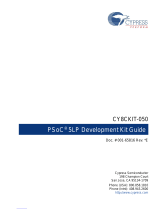
various circuits on the Shield board. Figure 3-1 shows the CY8CKIT-026 kit components.
Figure 3-1. CY8CKIT-026 CAN and LIN Shield Kit
1. DB9 female connector for CAN2
2. 12 V Power jack
3. 12 V input screw terminal
4. 12 V – 5 V power regulator
5. LIN2 I/O connector
6. LIN2 transceiver TJA1020T/CM
7. Cypress PMIC S6BP202A*
8. CAN2 transceiver TJA1051T/3
9. Power selection jumper
10. 3-Pin male connector for LIN2
11. 12 V power jumper (from LIN2)
12. CAN2 I/O connector
13. CAN2 termination resistor jumper
14. Arduino™ compatible main board
I/O header (J3 and J4)
15. LIN1 transceiver TJA1020
16. 3-Pin male connector for LIN1
17. 12 V power jumper (from LIN1)
18. CAN1 I/O connector
19. CAN1 transceiver TJA1055T/3C
20. Status LEDs
21. Arduino compatible main board I/O header (J2)
22. Arduino compatible main board power header (J1)
23. LIN1 I/O connector
24. 12 V power jumper (from CAN1)*
25. CAN1 screw terminal*
26. DB9 female connector for CAN1
27. CAN2 screw terminal*
28. 12 V power jumper (from CAN2)*
12
3
4
5
6
7
8
910
11
12
14
13
15
16
17
18
19
20
21
22
23
24
25 26 27 28
*Not populated


CY8CKIT-026 CAN and LIN Shield Kit Guide, Doc. No. 002-03798 Rev. *C 17
Hardware
3.2 CAN Physical Layer Transceiver Circuits
The CY8CKIT-026 has two CAN transceivers: one is low speed (up to 125 Kbps baud rate) and fault
tolerant, and the other is high speed (up to 2 Mbps baud rate). The PSoC 4M device supports two
CAN modules, so these two transceivers enable you to use both of them to connect to CAN net-
works.
The CAN physical layer transceiver circuits (CAN1 Transceiver and CAN2 Transceiver) on the shield
board use TJA1055T and TJA1051T CAN transceiver devices. These devices translate differential
CAN bus signals to and from digital CMOS signals.
■ CAN1 Transceiver (TJA1055T)
Three signals are used between this circuit and the CAN (PSoC 4) controller. These signals are
CAN1_RX, CAN1_TX, and CAN1_ERR. Data signals on the CAN bus are driven to the PSoC
CAN1_RX signal. Data signals on the PSoC CAN1_TX signal are driven onto the CAN bus. The
CAN1_ER signal is used to indicate an error event. See the TJA1055T device datasheet for details
on each of these three pins of the CAN transceiver.
■ CAN2 Transceiver (TJA1051T)
Three signals are used between this circuit and the CAN (PSoC 4) controller. These signals are
CAN_RX, CAN_TX, and CAN_EN. Data signals on the CAN bus are driven to the PSoC CAN2_RX
signal. Data signals on the PSoC CAN2_TX signal are driven onto the CAN bus. The CAN_EN
signal enables and disables the CAN transceiver. See the TJA1051T device datasheet for details on
each of these three pins of the CAN transceiver.
3.2.1 CAN Bus Clock Accuracy
For accurate CAN communication, a CAN controller device must typically have a clock source with a
frequency tolerance of 0.5% or less for bit-rates faster than 125 Kbps and at least 1.58% for
125 Kbps or slower bit-rates. Therefore, the device used as the CAN controller must meet this
requirement. Otherwise, an external clock source that is more accurate must be used. But, PSoC 4
has a great feature where you can trim the internal IMO clock up to 0.5% accuracy. See CE97311
code example for details on the clock configuration of this kit's code examples.
3.2.2 CAN Bus Connector
Table 3-1 shows the pinout of the CAN DB9 connectors (J8 and J17) on the shield board. The CAN
Bus connectors (DB9 connectors) for the two transceiver circuits have the same pin configuration.
Table 3-1. CAN Connector Point
Pin Signal
1
NC
2
CAN_L
3
GND
4NC
5NC
6GND
7CAN_H
8NC
9 NC (VIN = 12 V)

CY8CKIT-026 CAN and LIN Shield Kit Guide, Doc. No. 002-03798 Rev. *C 18
Hardware
By default, pin 9 of the CAN connector is left floating. However, if the jumper (J13 for CAN1
transceiver and J21 for CAN2 transceiver) is populated, pin 9 of the CAN connector is connected to
the VIN power rail of the Shield board. This is useful if you want to power up other CAN nodes
through the CAN connector or if you want to power up the Shield board from the power supply of
some other CAN node.
3.2.3 CAN Bus Termination for CAN1 Transceiver
The CAN specification requires that CAN nodes located physically at the end of the CAN bus must
terminate the CAN differential signals with 120 . TJA1055 has CAN Bus termination pins as RTH
and RTL which are connected to CAN_H and CAN_L with 120 respectively.
3.2.4 CAN Bus Termination for CAN2 Transceiver
The CAN specification requires that CAN nodes located physically at the end of the CAN bus must
terminate the CAN differential signals with 120. The Shield Kit features a 120- termination resis-
tor (R17) that can be enabled or disabled by using jumper J10. If J10 is populated, the termination
resistor is active. If J10 is not populated, the termination resistor is not active.
By default, the termination resistor is active (J10 is populated).
Figure 3-4. J10 Jumper
Caution: Ensure extra care when populating jumpers J13 or J21. The shield Kit or Pioneer Kit can
be damaged if the shield has it’s own power supply powering the VIN rail and a different power
supply is connected through pin 9 of the CAN connectors.

CY8CKIT-026 CAN and LIN Shield Kit Guide, Doc. No. 002-03798 Rev. *C 19
Hardware
3.2.5 Choke Footprint
A footprint for a common-mode signal suppression choke is available on the shield board for both
the transceiver circuits, but these are not populated. These footprints can be populated with a
B82789C0 (or equivalent) choke to suppress common-mode signals on the CAN bus. If a choke
component is mounted on the L2 footprint (for CAN1 transceiver), resistors R29 and R35
must be removed from the board. If a choke component is mounted on the L3 footprint (for
CAN2 transceiver), resistors R15 and R19 must be removed from the board. The choke
component has no effect if these two resistors are not removed.
Figure 3-5. Choke Footprints for CAN1 and CAN2 transceivers
3.2.6 CAN Signal Connector for CAN1 Transceiver
Table 3-2 shows the pinout of the 3-pin female CAN signal connector (J19) on the shield board.
CAN1_TX and CAN1_RX pins needs to be connected to the CAN TX pin, CAN_RX pin of the PSoC
(microcontroller) respectively, using external connecting wires. CAN1_ER pin is used for error
indication which should be connected to a GPIO pin of the microcontroller. These connections are
not hard-wired on the board so that maximum flexibility for the CAN pin placement in the
microcontroller is provided.
3.2.7 CAN Signal Connector for CAN2 Transceiver
Table 3-3 shows the pinout of the 3-pin female CAN signal connector (J9) on the shield board.
Table 3-2. CAN1 Signal Connector Pinout
Pin Signal
1
CAN1_TX
2
CAN1_RX
3
CAN1_ER
Table 3-3. CAN2 Signal Connector Pinout
Pin Signal
1
CAN2_EN
2
CAN2_TX
3
CAN2_RX

CY8CKIT-026 CAN and LIN Shield Kit Guide, Doc. No. 002-03798 Rev. *C 20
Hardware
CAN2_TX and CAN2_RX pins need to be connected to the CAN TX pin, CAN_RX pin of the PSoC
(microcontroller) respectively, using external connecting wires. CAN2_EN pin is used enable/disable
the transceiver which should be connected to the CAN_EN pin of the microcontroller. The trans-
ceiver is enabled by default. These connections are not hard-wired on the board so that maximum
flexibility for the CAN pin placement in the microcontroller is provided.
3.3 LIN Physical Layer Transceiver Circuits
The CY8CKIT-026 has two LIN transceivers. Since some PSoC 4 devices support two LIN slaves,
these two transceivers enable you to use both of them simultaneously.
The two LIN physical layer transceiver circuits on the shield board use a TJA1020 LIN
transceiver device. This device translates high-voltage LIN bus signals to and from digital CMOS
signals with standard TTL voltage levels.
Three signals are used between each LIN circuit and the LIN (PSoC 4) controller. For the LIN1 cir-
cuit, the three signals are: LIN1_RX, LIN1_TX, and LIN1_NSLP. For the LIN2 circuit, the signals are:
LIN2_RX, LIN2_TX, and LIN2_NSLP. Data signals on the LIN bus are sent to the PSoC by the
LINx_RX signal. Data signals driven by the PSoC on the LINx_TX signal will be driven onto the LIN
bus. The LINx_NSLP signals are used to put the LIN transceiver device in and out of sleep.
By default, there are no pull-up resistors on the LINx_TX signals. A pull-up resistor footprint is pro-
vided (R25 on LIN1_TX and R10 on LIN2_TX) on each LINx_TX signal if you want to have a pullup
resistor on this signal. See the TJA1020 device datasheet for details on each of the three signals of
the LIN transceiver.
3.3.1 LIN Bus Connectors
Figure 3-6 shows the pinout of both of the 3-pin LIN connectors (J14 for LIN1 transceiver and J5 for
LIN2 transceiver) on the shield board.
Figure 3-6. LIN Connector Pinouts
By default, the jumpers J16 and J7 are populated. These connect pin 3 (VBAT1) of the LIN1
connector and pin 3 (VBAT2) of the LIN2 connector to the VIN power rail of the Shield Kit,
respectively. This is useful if you want to power up other LIN nodes/analyzers through either of the
LIN connectors, or if you want to power the Pioneer Kit and shield board from the power supply
(12 V) of some other LIN node (LIN analyzer).
/