Cypress Semiconductor PSoC CapSense CY8CKIT-031 Kit Manual
- Type
- Kit Manual


2 CY8CKIT-031 PSoC CapSense Expansion Board Kit Guide, Doc. # 001-66474 Rev. *A
Copyrights
Copyrights
© Cypress Semiconductor Corporation, 2011. The information contained herein is subject to change without notice. Cypress
Semiconductor Corporation assumes no responsibility for the use of any circuitry other than circuitry embodied in a Cypress
product. Nor does it convey or imply any license under patent or other rights. Cypress products are not warranted nor
intended to be used for medical, life support, life saving, critical control or safety applications, unless pursuant to an express
written agreement with Cypress. Furthermore, Cypress does not authorize its products for use as critical components in life-
support systems where a malfunction or failure may reasonably be expected to result in significant injury to the user. The
inclusion of Cypress products in life-support systems application implies that the manufacturer assumes all risk of such use
and in doing so indemnifies Cypress against all charges.
Any Source Code (software and/or firmware) is owned by Cypress Semiconductor Corporation (Cypress) and is protected by
and subject to worldwide patent protection (United States and foreign), United States copyright laws and international treaty
provisions. Cypress hereby grants to licensee a personal, non-exclusive, non-transferable license to copy, use, modify, create
derivative works of, and compile the Cypress Source Code and derivative works for the sole purpose of creating custom soft-
ware and or firmware in support of licensee product to be used only in conjunction with a Cypress integrated circuit as speci-
fied in the applicable agreement. Any reproduction, modification, translation, compilation, or representation of this Source
Code except as specified above is prohibited without the express written permission of Cypress.
Disclaimer: CYPRESS MAKES NO WARRANTY OF ANY KIND, EXPRESS OR IMPLIED, WITH REGARD TO THIS MATE-
RIAL, INCLUDING, BUT NOT LIMITED TO, THE IMPLIED WARRANTIES OF MERCHANTABILITY AND FITNESS FOR A
PARTICULAR PURPOSE. Cypress reserves the right to make changes without further notice to the materials described
herein. Cypress does not assume any liability arising out of the application or use of any product or circuit described herein.
Cypress does not authorize its products for use as critical components in life-support systems where a malfunction or failure
may reasonably be expected to result in significant injury to the user. The inclusion of Cypress’ product in a life-support sys-
tems application implies that the manufacturer assumes all risk of such use and in doing so indemnifies Cypress against all
charges.
Use may be limited by and subject to the applicable Cypress software license agreement.
PSoC
®
and CapSense
®
are registered trademarks and PSoC Creator™ is a trademark of Cypress Semiconductor Corp. All
other trademarks or registered trademarks referenced herein are property of the respective corporations.
Flash Code Protection
Cypress products meet the specifications contained in their particular Cypress PSoC Data Sheets. Cypress believes that its
family of PSoC products is one of the most secure families of its kind on the market today, regardless of how they are used.
There may be methods, unknown to Cypress, that can breach the code protection features. Any of these methods, to our
knowledge, would be dishonest and possibly illegal. Neither Cypress nor any other semiconductor manufacturer can guaran-
tee the security of their code. Code protection does not mean that we are guaranteeing the product as ‘unbreakable’.
Cypress is willing to work with the customer who is concerned about the integrity of their code. Code protection is constantly
evolving. We at Cypress are committed to continuously improving the code protection features of our products.

CY8CKIT-031 PSoC CapSense Expansion Board Kit Guide, Doc. # 001-66474 Rev. *A 1
Contents
1. Introduction 3
1.1 Kit Contents .................................................................................................................3
1.2 PSoC Creator ..............................................................................................................3
1.3 Getting Started.............................................................................................................4
1.4 Additional Learning Resources....................................................................................4
1.5 Document History ........................................................................................................4
1.6 Documentation Conventions .......................................................................................4
2. Installation 5
2.1 CD Installation .............................................................................................................5
2.2 Hardware .....................................................................................................................6
2.3 Software.......................................................................................................................6
3. Kit Operation 7
4. Example Projects 9
4.1 Example Project 1: BMM_USB....................................................................................9
4.1.1 Project Description ...........................................................................................9
4.1.2 Hardware Connections..................................................................................10
4.1.3 Verify Output ..................................................................................................11
4.2 Example Project 2: SLM_USB...................................................................................11
4.2.1 Project Description .........................................................................................11
4.2.2 Hardware Connections...................................................................................12
4.2.3 Verify Output ..................................................................................................12
4.3 Example Project 3: BMM_I2C...................................................................................13
4.3.1 Project Description .........................................................................................13
4.3.2 Hardware Connections...................................................................................13
4.3.3 Verify Output ..................................................................................................14
4.4 Example Project 4: SLM_I2C.....................................................................................18
4.4.1 Project Description .........................................................................................18
4.4.2 Hardware Connections...................................................................................18
4.4.3 Verify Output ..................................................................................................19
A. Appendix 21
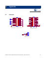
A.1 Schematic ..................................................................................................................21
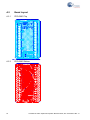
A.2 Board Layout .............................................................................................................22
A.2.1 PDC-09801 Top .............................................................................................22
A.2.2 PDC-09801 Bottom ........................................................................................22
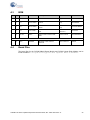
A.3 BOM ..........................................................................................................................23
A.4 Board Files.................................................................................................................23

2 CY8CKIT-031 PSoC CapSense Expansion Board Kit Guide, Doc. # 001-66474 Rev. *A
Contents

CY8CKIT-031 PSoC CapSense Expansion Board Kit Guide, Doc. # 001-66474 Rev. *A 3
1. Introduction
Thank you for your interest in the CY8CKIT-031 PSoC
®
CapSense
®
Expansion Board Kit. The
PSoC CapSense Expansion Board Kit interfaces any of the CY3280 Universal CapSense Module
boards with CY8CKIT-001 PSoC Development kit or CY8CKIT-030 PSoC 3 Development Kit. This
kit enables you to develop CapSense solutions with the CY8C3280 Universal CapSense Module
boards. The CapSense component in PSoC Creator™ allows to develop CapSense solutions with
great ease. The example projects provided along with this kit give sample solutions.
The PSoC CapSense Expansion Board is based on the PSoC 3 and PSoC 5 family of devices.
PSoC 3 and PSoC 5 are based on Programmable System-on-Chip™ platform for 8-, 16-, and 32-bit
applications. It combines precision analog and digital logic with a high-performance 8051 single
cycle per instruction pipelined processor achieving ten times the performance of previous 8051
processors. With this PSoC, you can create the exact combination of peripherals and integrated
proprietary IP to meet the needs of your applications. You are no longer constrained by what you find
in a catalog.
1.1 Kit Contents
The CY8CKIT-031 PSoC CapSense Expansion Board Kit includes:
■ CY8CKIT-031 PSoC CapSense Expansion Board
■ CY3280-BMM Universal CapSense Matrix Button Module Kit
■ CY3280-SLM Universal CapSense Linear Slider Module Kit
■ Two 1.5 mm overlay and one 3 mm overlay
■ Quick Start Guide
■ Resource CD
1.2 PSoC Creator
Cypress's PSoC Creator software is a state-of-the-art, easy-to-use integrated development
environment (IDE) that introduces a game-changing, hardware and software design environment
based on classic schematic entry and revolutionary embedded design methodology.
With PSoC Creator, you can:
■ Automatically place and route select components and integrate simple glue logic normally
located in discrete muxes.
■ Trade-off hardware and software design considerations allowing you to focus on what matters
and getting to market faster.
PSoC Creator also enables you to tap into an entire tools ecosystem with integrated compiler tool
chains, RTOS solutions, and production programmers to support both PSoC 3 and PSoC 5.

4 CY8CKIT-031 PSoC CapSense Expansion Board Kit Guide, Doc. # 001-66474 Rev. *A
Introduction
1.3 Getting Started
To get started, go to Kit Operation chapter on page 7 for a description of the kit operation. This
chapter explains how CapSense expansion board kit connects to develepement kit and CY8C3280
module boards. The Example Projects chapter on page 9 explains example projects provided with
the kit. The Appendix chapter on page 21 provides the schematics and BOM associated with the
CapSense Expansion Board Kit.
1.4 Additional Learning Resources
Visit www.cypress.com/go/training for additional learning resources in the form of data sheets,
technical reference manual, and application notes.
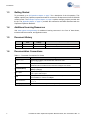
1.5 Document History
1.6 Documentation Conventions
Revision
PDF Creation
Date
Origin of
Change
Description of Change
** 03/09/11 PVKV Initial version of kit guide
*A 03/30/11 PVKV Added notes in Example Projects chapter on page 9
Table 1-1. Document Conventions for Guides
Convention Usage
Courier New
Displays file locations, user entered text, and source code:
C:\ ...cd\icc\
Italics
Displays file names and reference documentation:
Read about the sourcefile.hex file in the PSoC Designer User Guide.
[Bracketed, Bold]
Displays keyboard commands in procedures:
[Enter] or [Ctrl] [C]
File > Open
Represents menu paths:
File > Open > New Project
Bold
Displays commands, menu paths, and icon names in procedures:
Click the File icon and then click Open.
Times New Roman
Displays an equation:
2 + 2 = 4
Text in gray boxes Describes cautions or unique functionality of the product.

CY8CKIT-031 PSoC CapSense Expansion Board Kit Guide, Doc. # 001-66474 Rev. *A 5
2. Installation
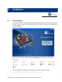
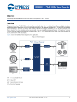
2.1 CD Installation
To install the CY8CKIT-031 PSoC CapSense Expansion Board Kit software, insert the kit CD into the
CD drive of your computer. The CD is designed to auto-run and PSoC CapSense Expansion Board
Kit menu appears.
Figure 2-1. Kit Menu
Note If auto-run does not execute, double-click AutoRun on the root directory of the CD.
After the installation is complete, the kit contents are found at the following location:
C:\Program Files\Cypress\PSoC CapSense EBK\1.0\

6 CY8CKIT-031 PSoC CapSense Expansion Board Kit Guide, Doc. # 001-66474 Rev. *A
Installation
The set up installs following software:
■ PSoC Creator
■ PSoC Programmer
■ Kit Documentation
❐ Quick Start Guide
❐ Kit Guide
❐ Known Problems and Solutions
❐ Release Notes
■ Firmware
❐ Example Projects
■ Hardware
❐ Schematic
❐ Layout
❐ BOM
2.2 Hardware
WARNING: Static discharges from the human body can easily reach 20,000 volts. This can damage
the PSoC 3 device on the development kit. Ensure that any static is discharged before touching the
hardware.
■ Ensure the development kit is powered off before making any connections
■ Connect the PSoC CapSense Expansion Board Kit to the development kit being used
■ Connect the CY3280-Universal CapSense Module Board to PSoC CapSense Expansion Board
Kit
■ Power the development kit
2.3 Software
When installing the PSoC CapSense Expansion Board Kit, the installer checks if prerequisites,
PSoC Creator, PSoC Programmer, Windows Installer, .NET, Acrobat Reader, and KEIL Complier,
are installed in your PC. If these applications are not installed, then the installer prompts you to
download and install them.

CY8CKIT-031 PSoC CapSense Expansion Board Kit Guide, Doc. # 001-66474 Rev. *A 7
3. Kit Operation
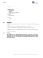
The following figure shows the CY8CKIT-031 PSoC CapSense Expansion Board Kit.
Figure 3-1. CY8CKIT-031 PSoC CapSense Expansion Board Kit
The following figure shows CY3280 CapSense Matrix Button Module.
Figure 3-2. CapSense Matrix Button Module
The following figure shows CY3280 CapSense Linear Slider Module.
Figure 3-3. CapSense Linear Slider Module
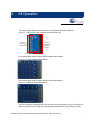
The PSoC CapSense Expansion Board Kit connects to the development kit using a 2×20-pin con-
nector. It connects to the CY3280 Universal CapSense Module Boards using 2×22-pin connector.
2x20-Pin
Connector for
DVK Interface
2x22 Pin
Connector for
CapSense
Interface
1x5 Pin Connector for I2C Interface

8 CY8CKIT-031 PSoC CapSense Expansion Board Kit Guide, Doc. # 001-66474 Rev. *A
Kit Operation
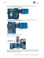
Figure 3-4. PSoC CapSense Expansion Board Kit Interface with PSoC Development Kit and
Universal CapSense Matrix Button Module Kit
Figure 3-5. PSoC CapSense Expansion Board Kit Interface with PSoC 3 Development Kit and
Universal CapSense Matrix Button Module Kit
The 5-pin connector provides the I
2
C interface.
Figure 3-6. I2C Connector
Note: The PSoC CapSense Expansion Board Kit can use only Port A of CY8CKIT-001 PSoC Devel-
opment Kit. Other ports Port A' , Port B, and Port C of PSoC Developement Kit cannot be used with
the PSoC CapSense Expansion Board Kit.
Miniprog3 connection to
I2C header for
communication with GUI

CY8CKIT-031 PSoC CapSense Expansion Board Kit Guide, Doc. # 001-66474 Rev. *A 9
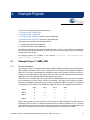
4. Example Projects
There are four example projects given with the kit.
1. Example Project 1: BMM_USB
2. Example Project 2: SLM_USB
3. Example Project 3: BMM_I2C (Works only with MiniProg3)
4. Example Project 4: SLM_I2C (Works only with MiniProg3)
The projects are provided for the development kits:
1. CY8CKIT-001 PSoC Development Kit
2. CY8CKIT-030 PSoC 3 Development Kit
The PSoC Development Kit projects are named with suffix _KIT-001. For the PSoC 3 Development
Kit the projects are named with suffix _KIT-030. User should use appropriate projects according to
development kit being used.
All example projects are available in the directory C:\Program Files\Cypress\PSoC
CapSense EBK\1.0\Firmware.
4.1 Example Project 1: BMM_USB
4.1.1 Project Description
This example shows the CapSense Matrix Button Module (BMM) interfacing with development kit
(Either PSoC Development Kit or PSoC 3 Development Kit) through PSoC CapSense Expansion
Board Kit. The project demonstrates the CapSense button matrix operation. When any button is
touched, the corresponding row and column LEDs are turned on. Also, the project shows calculator
application in PC with CapSense Matrix Button Module as key pad.
There are four row sensors and four column sensors on BMM module. When any button is touched,
the corresponding row and column sensors are activated. The project uses auto-tuning feature,
which sets all CapSense parameters to best values automatically. USBFS component is configured
as HID keyboard. The buttons on the BMM are mapped to keys on the calculator as shown below.
Before entering main loop, the code waits for two seconds for USB enumeration. An LED named as
Enumerate_LED is tuned on to indicate that wait time for the USB enumeration is over. The main
loop continuously scans all the sensors. If any of the buttons is touched then the corresponding row
LED and column LED are turned on and corresponding key code is sent to PC via USB.
Col 0 Col 1 Col 2 Col3
Row 0
0123
Row 1
4567
Row 2
89
.
=
Row 3
+-*/

10 CY8CKIT-031 PSoC CapSense Expansion Board Kit Guide, Doc. # 001-66474 Rev. *A
Example Projects
The Sensitivity parameter in CapSense_CSD component configuration is set to 4 and project is
tested to work without any overlay. When an overlay of some thickness is used, the sensitivity
parameter should be changed in the project as shown in below Figure 4-1. The sensitivity parameter
indicates the finger capacitance which depends on the button area, overlay thickness and dielectric
constant of overlay material. Options for sensitivity are 1 to 4. When it is set to 1, this indicates when
finger is touched on button it adds 0.1 pF of capacitance. Similarly when it is set to 4, this indicates
when finger is touched on button it adds 0.4 pF of capacitance.
Figure 4-1. Sensitivity Parameter Setting
4.1.2 Hardware Connections
If the development kit is PSoC Development Kit, then
■ Connect the CapSense Matrix Button Module to connector J2 of PSoC CapSense Expansion
Board.
■ Connect the J1 of PSoC CapSense Expansion Board to the port A of the development kit.
■ Connect the jumper J2 on the CapSense Matrix Button Module to short SHIELD and SHLD.
■ Connect USB cable from J9 on the development kit to the PC USB port.
■ Connect P1[6] to LED1. This LED is used in the project with name Enumerate_LED to
indicate that USB enumeration is complete.
If the development kit is PSoC 3 Development Kit, then
■ Connect the CapSense Matrix Button Module to connector J2 of PSoC CapSense Expansion
Board.
■ Connect the J1 of PSoC CapSense Expansion Board to the port D of the development kit.
■ Connect the jumper J2 on the CapSense Matrix Button Module to short SHIELD and SHLD.
■ Connect USB cable from J2 on the development kit to the PC USB port.
■ Pin P6[3] is used for Enumerate_LED, which is connected to LED4 on the board itself, therefore
there is no need of explicit connection.
■ Remove LCD from port P8. LCD module adds parasitic capacitance and noise to CapSense
because it shares the same pins of Port D which are used for CapSense.
■ If Miniprog3 is used for programming then disconnect it from J3 after programming. The program-
ming port J3 shares the port D pins and adds the noise on CapSense if Miniprog3 is present.

CY8CKIT-031 PSoC CapSense Expansion Board Kit Guide, Doc. # 001-66474 Rev. *A 11
Example Projects
4.1.3 Verify Output
Build and program the example project and reset the device. After device is reset, wait for
Enumerate_LED to turn on. The LED indicates that 2 seconds wait time for the USB enumeration is
over. Touch a button and see the corresponding row and column LED turns on. Open the calculator
application in the PC, touch any button the corresponding key is pressed on calculator. Perform
different operations on calculator using CapSense touch buttons.
Figure 4-2. CapSense Matrix Button Module Project
4.2 Example Project 2: SLM_USB
4.2.1 Project Description
This example shows the CapSense Linear Slider Module (SLM) interfacing with development kit
(Either PSoC Development Kit or PSoC 3 Development Kit) through PSoC CapSense Expansion
Board Kit. The project demonstrates the CapSense slider and button combination. When any button
is touched on the module the corresponding LED is turned on and when finger is placed on the
slider, the nearest LED to the finger position is turned on. Also, the project shows media player
application in PC with buttons and slider on CapSense Linear Slider Module as media controls such
as play/pause, volume control etc.
The SLM module has 10 element slider and five buttons. The module also has five LEDs. The finger
position on the slider is indicated by turning on the nearest LED. The active button is indicated by
turning on corresponding LED. The project uses the auto-tuning feature, which sets all CapSense
parameters to best values automatically. USBFS user module is configured as HID keyboard. The
buttons and slider on the SLM are used as controls for the media player as below.
BTN0 Play/Pause
BTN1 Stop
BTN2 Mute/UnMute
BTN3 Next Track
BTN4 Previous Track
Slider Left/Right - Volume UP/DOWN
Before entering the main loop, the code waits for two seconds for USB enumeration. An LED named
as Enumerate_LED is tuned on to indicate that wait time for the USB enumeration is over. The main
loop continuously scans all the sensors. LEDs are updated based on active buttons and finger
position on the slider and key code is sent to PC via USB.
The Sensitivity parameter in CapSense_CSD component configuration is set to 4 and project is
tested to work without any overlay. When overlay is used, the sensitivity parameter should be
changed in the project as shown in Figure 4-1 on page 10.

12 CY8CKIT-031 PSoC CapSense Expansion Board Kit Guide, Doc. # 001-66474 Rev. *A
Example Projects
4.2.2 Hardware Connections
If the development kit is PSoC Development Kit, then
■ Connect the CapSense Linear Slider Module to connector J2 of PSoC CapSense Expansion
Board.
■ Connect the J1 of PSoC CapSense Expansion Board Kit to the port A of the development kit.
■ Connect the jumper J2 on the CapSense Linear Slider Module to short SHIELD and SHLD.
■ Connect USB cable from J9 on the development kit to the PC USB port.
■ Connect P1[6] to LED1. This LED is used in the project with name Enumerate_LED to
indicate that USB enumeration is complete.
If the development kit is PSoC 3 Development Kit, then
■ Connect the CapSense Linear Slider Module to connector J2 of PSoC CapSense Expansion
Board.
■ Connect the J1 of PSoC CapSense Expansion Board Kit to the port D of the development kit.
■ Connect the jumper J2 on the CapSense Linear Slider Module to short SHIELD and SHLD.
■ Connect USB cable from J2 on the development kit to the PC USB port.
■ Pin P6[3] is used for Enumerate_LED, which is connected to LED4 on the board itself, therefore
there is no need of explicit connection.
■ Remove LCD from port P8. LCD module adds parasitic capacitance and noise to CapSense
because it shares the same pins of Port D which are used for CapSense.
■ If Miniprog3 is used for programming then disconnect it from J3 after programming. The program-
ming port J3 shares the port D pins and adds the noise on CapSense if Miniprog3 is present.
4.2.3 Verify Output
Build and program the example project and reset the device. After device is reset, wait for
Enumerate_LED to turn on. The LED indicates that 2 seconds wait time for the USB enumeration is
over. Touch a button and see the corresponding row and column LED turns on. Place finger on the
slider and see nearest LED turned on. Open the Windows Media Player 11 application in the PC.
Perform different operations such as Perform different operations, such as Play/Pause, Next,
Previous, and Volume Control using CapSense Linear Slider Module touch controls.
Figure 4-3. CapSense Linear Slider Module Project

CY8CKIT-031 PSoC CapSense Expansion Board Kit Guide, Doc. # 001-66474 Rev. *A 13
Example Projects
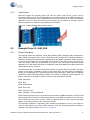
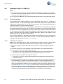
4.3 Example Project 3: BMM_I2C
Note: The project uses the Miniprog3. It does not work without MiniProg3 because the code waits
forever in the main loop if I2C communication is not set up. User can buy MiniProg3 through this link
www.cypress.com/go/CY8CKIT-002.
4.3.1 Project Description
This example project shows CapSense Matrix Button Module with "Tuner" for monitoring of
CapSense outputs. The CapSense outputs such as Rawcounts, Baseline and Signal (Difference
count) can be monitored on the "Tuner" GUI. The project uses Auto Tuning feature which sets all
CapSense parameters to best values automatically. The parameters settings can be monitored in
the GUI but cannot be altered because they are set by auto tuning. If tuning method is set to Manual,
then parameter settings can be changed in the GUI and output can be seen as a result of the
changes.
The project also makes use of LEDs on the CapSense Matrix Button Module board. When button is
touched the corresponding LED is turned on. The code uses Tuner APIs. The tuner API
CapSense_TunerComm() is used in main loop to scan sensors, which also sends the CapSense
variables RawCounts, Baseline, and Difference counts (Signal) to the PC GUI, through I2C
communication.
The Sensitivity parameter in CapSense_CSD component configuration is set to 4 and project is
tested to work without any overlay. When overlay of some thickness is used, the sensitivity
parameter should be changed in the project as shown in Figure 4-1 on page 10.
4.3.2 Hardware Connections
■ Connect the CapSense Matrix Button Module to connector J2 of PSoC CapSense Expansion
Board.
■ If the development kit is PSoC Development Kit, then connect the J1 of PSoC CapSense Expan-
sion Board Kit to port A of the development kit.
■ If the development kit is PSoC 3 Development Kit, then connect the J1 of PSoC CapSense
Expansion Board Kit to port D of the development kit. Remove LCD from port P8. LCD module
adds parasitic capacitance and noise to CapSense because it shares the same pins of Port D
which are used for CapSense.
■ Connect the jumper J2 on the CapSense Matrix Button Slider Module to short SHIELD and
SHLD.
■ If Miniprog3 is used for programming the device, then disconnect it from programming port and
PC. The Miniprog3 is used for I2C communication purpose. Connect the Miniprog3 to the J3
header on the PSoC CapSense Expansion Board Kit. Make sure that I2C pins SDA, SCL, and
GND on the Miniprog3 are mapped on to corresponding I2C pins on the PSoC CapSense Expan-
sion Board Kit. See Figure 3-6 on page 8 for the connections. Note that when MiniProg3 is used
for both I2C and programming, the Miniprog3 should be disconnected from PC every time con-
nection is changed. For example, when Miniprog3 is used for programming, then it should be dis-
connected from both programming port and PC before it is used for I2C communication.

14 CY8CKIT-031 PSoC CapSense Expansion Board Kit Guide, Doc. # 001-66474 Rev. *A
Example Projects
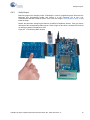
4.3.3 Verify Output
Build and program the example project. If Miniprog3 is used for programming then disconnect the
Miniprog3 from programming header and connect it to I2C connector J3 on PSoC CapSense
Expansion Board Kit to use it for communication with GUI. Reset the device.
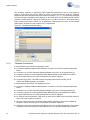
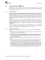
Tuner GUI Usage:
1. To open the Tuner, right click on the CapSense_CSD component in PSoC Creator and click on
Launch Tuner.
2. Click on the Configuration button to open the configuration window.

CY8CKIT-031 PSoC CapSense Expansion Board Kit Guide, Doc. # 001-66474 Rev. *A 15
Example Projects
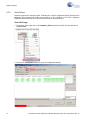
3. Set the I2C communication parameters same as set in the EZI2C component.
Note: The I2C Voltage should be other than External. The external supply pin on the MiniProg3
VTARG connects to NC on the CY8CKIT-031 board. Therefore the external supply option does
not work with the CY8CKIT-030. Select any option for the I2C Voltage other than External.
4. Click OK to apply the settings.

16 CY8CKIT-031 PSoC CapSense Expansion Board Kit Guide, Doc. # 001-66474 Rev. *A
Example Projects
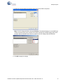
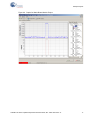
5. To start the scanning and communication process, click Start button.
6. Open the Graphics tab; it shows different CapSense results RawCounts, Baseline, and
Difference count (signal) for each sensor.
7. Check the graph to enable it. See graph for different variables.
8. Touch the button and observe the increase in counts.
9. Open the General tab and select a sensor. Different CapSense parameters are shown on the
bottom-right. Because auto-tuning is used in this project, you cannot edit the settings. Auto-tun-
ing automatically sets all the parameters. The GUI is used to monitor the CapSense variables
RawCounts, Baseline, and Signal for all sensors.
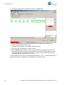
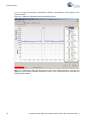
Touch any button and observe the corresponding LED turned on. Figure 4-4 shows the monitoring of
RawCounts, Baseline, and Difference count (signal) for the Column 0 sensor.

CY8CKIT-031 PSoC CapSense Expansion Board Kit Guide, Doc. # 001-66474 Rev. *A 17
Example Projects
Figure 4-4. Graphs for Matrix Button Module Project

18 CY8CKIT-031 PSoC CapSense Expansion Board Kit Guide, Doc. # 001-66474 Rev. *A
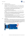
Example Projects
4.4 Example Project 4: SLM_I2C
Notes:
■ The project uses the Miniprog3. It does not work without MiniProg3 because the code waits for-
ever in the main loop if I2C communication is not set up. User can buy MiniProg3 through this link
www.cypress.com/go/CY8CKIT-002.
■ This project uses Port E for PSoC 3 Development Kit and includes LCD to display slider position.
4.4.1 Project Description
This example project shows CapSense Linear Slider Module with "Tuner" for monitoring of
CapSense outputs. The CapSense outputs such as Rawcounts, Baseline and Signal (Difference
count) can be monitored on the "Tuner" GUI. The project uses Auto Tuning feature which sets all
CapSense parameters to best values automatically.
The project includes character LCD for displaying the slider position. The slider position is displayed
as horizontal bar graph on the char LCD. The LEDs on the CapSense Linear Slider on Module board
are turned on when corresponding button is touched. When slider is touched, nearest LED is turned
on. The code uses Tuner APIs. The tuner API CapSense_TunerComm() is used in main loop to scan
sensors, which also sends the CapSense variables RawCounts, Baseline, and Difference counts
(Signal) to the PC GUI, through I2C communication.
The Sensitivity parameter in CapSense_CSD component configuration is set to 4 and project is
tested to work without any overlay. When overlay is used, the sensitivity parameter should be
changed in the project as shown in Figure 4-1 on page 10.
4.4.2 Hardware Connections
Note: Project uses Port E for the PSoC 3 Development Kit instead of Port D as with the other
projects. This is to accommodate LCD which uses the same pins of port D as the CapSense.
■ Connect the CapSense Linear Slider Module to connector J2 of PSoC CapSense Expansion
Board.
■ Connect the jumper J2 on the CapSense Linear Slider Module to short SHIELD and SHLD.
■ If the development kit is PSoC Development Kit, then
❐ Connect the J1 of PSoC CapSense Expansion Board Kit to port A of the development kit.
❐ Connect LCD to P18 and place jumper J12 to ON position to power on the LCD.
■ If the development kit is PSoC 3 Development Kit, then
❐ Connect the J1 of PSoC CapSense Expansion Board Kit to port E of the development kit.
❐ Connect LCD to P8.
■ If Miniprog3 is used for programming the device, then disconnect it from programming port and
PC. The Miniprog3 is used for I2C communication purpose. Connect the Miniprog3 to the J3
header on the PSoC CapSense Expansion Board Kit. Make sure that I2C pins SDA, SCL, and
GND on the Miniprog3 are mapped on to corresponding I2C pins on the PSoC CapSense Expan-
sion Board Kit. See Figure 3-6 on page 8 for the connections. Note that when MiniProg3 is used
for both I2C and programming, the Miniprog3 should be disconnected from PC every time con-
nection is changed. For example, when Miniprog3 is used for programming, then it should be dis-
connected from both programming port and PC before it is used for I2C communication.
Page is loading ...
Page is loading ...
Page is loading ...
Page is loading ...
Page is loading ...
Page is loading ...
-
 1
1
-
 2
2
-
 3
3
-
 4
4
-
 5
5
-
 6
6
-
 7
7
-
 8
8
-
 9
9
-
 10
10
-
 11
11
-
 12
12
-
 13
13
-
 14
14
-
 15
15
-
 16
16
-
 17
17
-
 18
18
-
 19
19
-
 20
20
-
 21
21
-
 22
22
-
 23
23
-
 24
24
-
 25
25
-
 26
26


Cypress Semiconductor PSoC CapSense CY8CKIT-031 Kit Manual
- Type
- Kit Manual
Ask a question and I''ll find the answer in the document
Finding information in a document is now easier with AI
Related papers
-
Cypress Semiconductor CY8CKIT-042-BLE User manual
-
-
-
-
Infineon CY8CKIT-024 User manual
-
-
-
-
-
 Cypress CPSoC User manual

Other documents
-
 Cypress CY8CKIT-044 User manual
-
 Cypress CY3203-CapSense Quick start guide
-
 Cypress CY3270 User manual
-
 Cypress CY8C22113 User manual
-
 Cypress CapSense CY8C20x66 User manual
-
 Cypress CY8CKIT-050 User manual
-
-
 Cypress PSoC 6 MCU User manual
-
-
Infineon CY8CKIT-148 User manual


