Page is loading ...

CE222221 – PSoC 6 MCU Voice Recorder
www.cypress.com Document Number: 002-22221 Rev. *C 1
Objective
This example demonstrates the use of PSoC® 6 MCU to implement a voice recorder.
Overview
This project shows how PSoC 6 MCU can be used to record audio data, store it and play it back. It uses a digital microphone
with the pulse-density modulation (PDM) to pulse-code modulation (PCM) converter hardware block. All the audio data captured
by the microphone is stored to an external flash memory. After the recording is completed, you can play the audio data over
Inter-IC Sound (I2S), which interfaces with an audio codec. You can record/stop/play/pause/resume with CapSense® buttons.
You can control the audio volume with the CapSense slider. The TFT LCD displays the current state of the voice recorder, the
volume, and the time of the record/play.
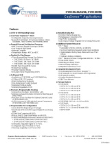
Figure 1 shows the high level-block diagram of this application.
Figure 1. Block Diagram
UDB = Universal Digital Blocks
QSPI = Quad-SPI
SMIF = Serial Memory Interface
TFT = Thin-Film Transistor

PSoC 6 MCU Voice Recorder
www.cypress.com Document Number: 002-22221 Rev. *C 2
Requirements
Tool: PSoC Creator™ 4.2; Peripheral Driver Library (PDL) 3.0.1
Programming Language: C (Arm® GCC 5.4.1)
Associated Parts: All PSoC 6 MCU parts
Related Hardware: CY8CKIT-062-WiFi-BT, CY8CKIT-028-TFT
Software Setup
Check if all the latest components are available in PSoC Creator. Go to menu Tools > Find New Components. Install all the new
components in the list, if any.
Hardware Setup
This example requires the CY8CKIT-028-TFT shield to be connected to CY8CKIT-062-WiFi-BT PSoC 6 Pioneer Kit. Keep SW5
and SW7 in their default positions. Refer to the Kit Guide for more information. You also need a headphone or speaker connected
to the audio jack on the CY8CKIT-028-TFT shield. The SW1 position should match the type of headphone/speaker used – OMTP
[Open Mobile Terminal Platform] or AHJ [American Headset Jack].
Operation
1. Connect the CY8CKIT-028-TFT shield to the Pioneer Kit.
2. Connect a headphone or speaker to the audio jack on the CY8CKIT-028-TFT.
3. Connect the Pioneer Kit to your PC using the provided USB cable through the USB connector (J10).
4. Build the project and program it into the PSoC 6 MCU device. Choose Debug > Program. When building the project, DO
NOT replace the FreeRTOSConfig.h file. For more information on device programming, see PSoC Creator Help. Flash for
both CPUs is programmed in a single program operation.
After pressing the RST button, the following screen appears on the TFT LCD display.
Vol: 91% 0:00
5. Press the left CapSense button (BTN0) on CY8CKIT-062 to start recording. The following screen appears on the TFT LCD.
Vol: 91% 0:01
6. Play a sound, or speak over the microphone (PDM MIC) on CY8CKIT-028-TFT while recording.
7. Press the left CapSense button again to stop recording. The following screen appears on the LCD.
Vol: 91% 0:15
8. Press the right CapSense button (BTN1) to play the recording. The following screen appears on the LCD.

PSoC 6 MCU Voice Recorder
www.cypress.com Document Number: 002-22221 Rev. *C 3
Vol: 91% 0:01
9. Listen to the recorded audio using the headphone or speaker. You can pause/resume any time by pressing the right
CapSense button again. If paused, the following screen appears on the LCD:
Vol: 91% 0:07
10. To change the volume, slide your finger on the CapSense slider to the right (increase volume) or to the left (decrease
volume).
Design and Implementation
The CY8CKIT-028-TFT shield contains the audio codec AK4954A, an audio jack, a digital microphone, and a Newhaven 2.4-
inch 240x320 TFT LCD display with a Sitronix ST7789 display controller. This allows you to record audio using the microphone
and play it with the audio codec. The display is used to report the current state of the voice recorder – IDLE, RECORDING,
PLAYING, or PAUSED. The Pioneer kit contains two CapSense buttons and a slider. The buttons trigger the actions supported
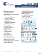
by the voice recorder. Figure 2 shows how the transitions between states occur.
Figure 2. States and Transitions
IDLE RECORDING
PLAYINGPAUSED
BTN0 : Record Button
BTN1 : Play Button
BTN0
BTN0
BTN1
BTN1
BTN1
BTN1
BTN0
BTN0
Each state is linked to a different icon displayed in the LCD. The Operation section shows the screenshots of each state. The
screen also shows the current volume in percent, and the time duration of the record/play. The GraphLCDIntf Component drives
the LCD. It is configured to have an 8-bit wide bus. The example uses an open-source graphics library for embedded system
called µGUI. The firmware uses this library to draw text and figures on the LCD display.
When recording, the PDM/PCM hardware block captures the data from the digital microphone. All the data written to its internal
FIFO is transferred (using DMAs) to a circular buffer placed in the SRAM. The DMA is configured to generate interrupts when a
certain amount of data is transferred. On each interrupt, the application transfers data from the circular buffer to the external
memory over QuadSPI (SMIF). This memory is placed on Pioneer Kit and uses NOR flash technology (S25FL512S).
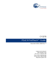
When playing, the I2S hardware block streams the recorded data. The application reads the data from the external memory and
places it in a ping-pong buffer. While writing in the ping buffer, a DMA controller transfers the data from the pong buffer to the
I2S TX FIFO. Figure 3 shows the overall transfers performed by the application.

PSoC 6 MCU Voice Recorder
www.cypress.com Document Number: 002-22221 Rev. *C 4
Figure 3. Overall Transfers
PDM/PCM
RX FIFO
SRAM
Circular
Buffer
External
Memory Ping-Pong
buffer I2S TX
FIFO
DMA
Transfers Write
Memory Calls Read
Memory Calls DMA
Transfers
When in the IDLE or PAUSED states, no transfers are performed.
To minimize writing in the same sector of the external memory multiple times, a wearing level mechanism is implemented. On
initialization, the application scans the external memory to locate the last sector written by the application. Every time a new
record is started, the application erases and writes new data in the next sector available. This mechanism reduces the number
of times the same sector is erased/written. The same sector will only be erased/written when all other sectors are used.
The firmware uses FreeRTOS to execute the processes required by this application. All tasks run in the Arm® Cortex®-M4 CPU.
The following tasks are created:
1. RecorderTask: handles recording and playing. It controls the transfers between the FIFOs, SRAM, and external memory.
2. TouchTask: handles CapSense touches on the buttons and slider.
3. EventsTask: handles any events that occur, such as touches from CapSense or recording/playing events.
4. GraphicsTask: handles updates and draws on the LCD.
Other RTOS elements used for synchronization and communication are:
1. Event Queue: used to notify EventsTask when specific events occur. The RecorderTask and TouchTask are senders.
2. GUI Queue: used to notify GraphicsTask to update or draw something on the screen. RecorderTask and EventsTask are
senders.
3. SMIF Semaphore: used to lock the SMIF interface for accessing the external memory.
4. DMA Event Group Bits: used to notify RecorderTask that a DMA interrupt occurred.
Components and Settings
Table 1 lists the PSoC Creator Components used in this example, how they are used in the design, and the non-default settings
required so they function as intended.
Table 1. PSoC Creator Components
Component
Instance Name
Purpose
Non-default Settings
PDM to PCM
PDM_PCM
Interface the digital microphone
See Figure 4
SMIF
SMIF_1
Interface the external flash memory
SMIF Datalines[0:1] checked
SMIF Datalines[2:3] checked
SMIF SPI Slave Select 0 checked
Generate code from cy_smif.cysmif file checked
All other parameters unchecked
See Figure 5 for SMIF Configuration Tool
(Launch by clicking with right mouse button over
the SMIF component)
DMA
DMA_Record
Transfer data from PDM/PCM RX
FIFO to SRAM
Trigger Input/Output are checked
See Figure 6
DMA
DMA_PlayLeft
Transfer data from SRAM to I2S TX
FIFO (left channel)
Trigger Input/Output are checked
See Figure 7

PSoC 6 MCU Voice Recorder
www.cypress.com Document Number: 002-22221 Rev. *C 5
Component
Instance Name
Purpose
Non-default Settings
DMA
DMA_PlayRight
Transfer data from SRAM to I2S TX
FIFO (right channel)
Trigger Input/Output are checked
See Figure 8
I2S
I2S
Interface the audio codec
See Figure 9
SCB (I2C Master)
CodecI2CM
Configure the audio codec
Mode: Master
CapSense
CapSense
Scan capacitive buttons and a slider
See Figure 10 to Figure 13
GraphicLCDIntf
GraphicLCDIntf
Interface the TFT LCD Display
Bus Width: 8 bit
Interrupt
DMA_PDM_IRQ
Track the recording transfers
Interrupt
DMA_I2S_IRQ
Track the playing transfers
Clock
Clk_HF4
Master clock for the audio codec
Clock
Clock_Graphics
Clock for GraphicLCDIntf
Digital Input Pin
PDM_DATA
PDM Data input
Digital Output Pin
PDM_CLK
PDM Clock output
Digital Output Pin
TX_SDO
I2S TX Data output
Digital Output Pin
TX_SCK
I2S TX Clock output
Digital Output Pin
TX_WS
I2S TX Word Select output
Digital Output Pin
Pin_d_c
Data/Command signal for the LCD
Digital Output Pin
Pin_ncs
Active-LOW chip select for the LCD
Digital Output Pin
Pin_nwr
Active-LOW write control signal for
LCD
Digital Output Pin
Pin_nrd
Active-LOW read control signal for
LCD
Digital Output Pin
Intf_nreset
Active-LOW reset signal for the LCD
HW Connection is Unchecked
Bidirectional Pin
Pin_LSB
8-bit pin bus for the LCD
Number of pins: 8
Digital Output Pin
RED_LED
Assert when an error is detected
Initial drive state: High
HW Connection is Unchecked
For information on the hardware resources used by a Component, see the Component datasheet.
Figure 4 through Figure 10 highlight the non-default settings for each Component in this example.


PSoC 6 MCU Voice Recorder
www.cypress.com Document Number: 002-22221 Rev. *C 14
Figure 16. High Frequency Clocks Configuration
Reusing This Example
This example is designed for the CY8CKIT-062-WiFi-BT PSoC 6 Pioneer kit. To port the design to a different PSoC 6 MCU
device and/or kit, change the target device using Device Selector and update the pin assignments in the Design Wide Resources
Pins settings as needed.
In some cases, a resource used by a code example (for example, an IP block) is not supported on another device. In such cases,
the example will not work. If you build the code targeted at such a device, you will get errors. See the device datasheet for
information on what a particular device supports.
This example also uses an external 17.2032 ECO placed on CY8CKIT-062-WiFi-BT PSoC 6 Pioneer kit. If you are using another
kit that does not contain such ECO, edit the clock configuration to source the PLL from the IMO.

PSoC 6 MCU Voice Recorder
www.cypress.com Document Number: 002-22221 Rev. *C 15
Related Documents
Application Notes
AN210781 – Getting Started with PSoC 6 MCU
with Bluetooth Low Energy (BLE) Connectivity
Describes the PSoC 6 BLE, and how to build this code example
AN217666 – PSoC 6 MCU Interrupts
Describes how to use interrupts in PSoC 6 MCU
PSoC Creator Component Datasheets
Inter-IC Sound Bus (I2S) Component
Sends digital audio streaming data to external I2S devices
Inter-Integrated Circuit (I2C) Component
Supports I2C slave, master, and master-slave operation configurations.
PDM to PCM Decoder Component
Converts a PDM signal to PCM.
Direct Memory Access (DMA) Component
Transfers data to and from memory and registers.
Capacitive Sensing (CapSense) Component
Scan capacitive buttons, sliders, touch pad, proximity sensors
Serial Memory Interface (SMIF) Component
Interface external serial memories
Device Documentation
PSoC 6 MCU: PSoC 63 with BLE Datasheet (PRELIMINARY)
PSoC 6 MCU: PSoC 63 with BLE Architecture Technical Reference Manual
PSoC 6 MCU: PSoC 63 with BLE Register Technical Reference Manual
PSoC 6 MCU: PSoC 62 Datasheet
PSoC 6 MCU: PSoC 62 Register Technical Reference Manual
Development Kit (DVK) Documentation
CY8CKIT-062-BLE PSoC 6 BLE Pioneer Kit
CY8CKIT-062-WiFi-BT PSoC 6 Pioneer Kit

PSoC 6 MCU Voice Recorder
www.cypress.com Document Number: 002-22221 Rev. *C 16
Document History
Document Title: CE222221 – PSoC 6 MCU Voice Recorder
Document Number: 002-22221
Revision
ECN
Orig. of
Change
Submission
Date
Description of Change
**
6001270
RLOS
01/05/2018
New code example
*A
6261637
RLOS
06/26/2018
Added a few acronyms
Fixed some minor typos
Added Software Setup section
*B
6406806
SRDS
12/10/2018
Added the TFT display model details.
*C
6509595
SRDS
03/15/2019
Updated the TFT display link.
Updated template

PSoC 6 MCU Voice Recorder
www.cypress.com Document Number: 002-22221 Rev. *C 17
Worldwide Sales and Design Support
Cypress maintains a worldwide network of offices, solution centers, manufacturer’s representatives, and distributors. To find the
office closest to you, visit us at Cypress Locations.
Products
Arm® Cortex® Microcontrollers
cypress.com/arm
Automotive
cypress.com/automotive
Clocks & Buffers
cypress.com/clocks
Interface
cypress.com/interface
Internet of Things
cypress.com/iot
Memory
cypress.com/memory
Microcontrollers
cypress.com/mcu
PSoC
cypress.com/psoc
Power Management ICs
cypress.com/pmic
Touch Sensing
cypress.com/touch
USB Controllers
cypress.com/usb
Wireless Connectivity
cypress.com/wireless
PSoC® Solutions
PSoC 1 | PSoC 3 | PSoC 4 | PSoC 5LP | PSoC 6 MCU
Cypress Developer Community
Community | Code Examples | Projects | Videos | Blogs
| Training | Components
Technical Support
cypress.com/support
All other trademarks or registered trademarks referenced herein are the property of their respective owners.
Cypress Semiconductor
198 Champion Court
San Jose, CA 95134-1709
© Cypress Semiconductor Corporation, 2018-2019. This document is the property of Cypress Semiconductor Corporation and its subsidiaries (“Cypress”). This
document, including any software or firmware included or referenced in this document (“Software”), is owned by Cypress under the intellectual property laws and
treaties of the United States and other countries worldwide. Cypress reserves all rights under such laws and treaties and does not, except as specifically stated in
this paragraph, grant any license under its patents, copyrights, trademarks, or other intellectual property rights. If the Software is not accompanied by a license
agreement and you do not otherwise have a written agreement with Cypress governing the use of the Software, then Cypress hereby grants you a personal, non-
exclusive, nontransferable license (without the right to sublicense) (1) under its copyright rights in the Software (a) for Software provided in source code form, to
modify and reproduce the Software solely for use with Cypress hardware products, only internally within your organization, and (b) to distribute the Software in binary
code form externally to end users (either directly or indirectly through resellers and distributors), solely for use on Cypress hardware product units, and (2) under
those claims of Cypress’s patents that are infringed by the Software (as provided by Cypress, unmodified) to make, use, distribute, and import the Software solely
for use with Cypress hardware products. Any other use, reproduction, modification, translation, or compilation of the Software is prohibited.
TO THE EXTENT PERMITTED BY APPLICABLE LAW, CYPRESS MAKES NO WARRANTY OF ANY KIND, EXPRESS OR IMPLIED, WITH REGARD TO THIS
DOCUMENT OR ANY SOFTWARE OR ACCOMPANYING HARDWARE, INCLUDING, BUT NOT LIMITED TO, THE IMPLIED WARRANTIES OF
MERCHANTABILITY AND FITNESS FOR A PARTICULAR PURPOSE. No computing device can be absolutely secure. Therefore, despite security measures
implemented in Cypress hardware or software products, Cypress shall have no liability arising out of any security breach, such as unauthorized access to or use of
a Cypress product. CYPRESS DOES NOT REPRESENT, WARRANT, OR GUARANTEE THAT CYPRESS PRODUCTS, OR SYSTEMS CREATED USING
CYPRESS PRODUCTS, WILL BE FREE FROM CORRUPTION, ATTACK, VIRUSES, INTERFERENCE, HACKING, DATA LOSS OR THEFT, OR OTHER
SECURITY INTRUSION (collectively, “Security Breach”). Cypress disclaims any liability relating to any Security Breach, and you shall and hereby do release
Cypress from any claim, damage, or other liability arising from any Security Breach. In addition, the products described in these materials may contain design
defects or errors known as errata which may cause the product to deviate from published specifications. To the extent permitted by applicable law, Cypress reserves
the right to make changes to this document without further notice. Cypress does not assume any liability arising out of the application or use of any product or circuit
described in this document. Any information provided in this document, including any sample design information or programming code, is provided only for reference
purposes. It is the responsibility of the user of this document to properly design, program, and test the functionality and safety of any application made of this
information and any resulting product. “High-Risk Device” means any device or system whose failure could cause personal injury, death, or property damage.
Examples of High-Risk Devices are weapons, nuclear installations, surgical implants, and other medical devices. “Critical Component” means any component of a
High-Risk Device whose failure to perform can be reasonably expected to cause, directly or indirectly, the failure of the High-Risk Device, or to affect its safety or
effectiveness. Cypress is not liable, in whole or in part, and you shall and hereby do release Cypress from any claim, damage, or other liability arising from any use
of a Cypress product as a Critical Component in a High-Risk Device. You shall indemnify and hold Cypress, its directors, officers, employees, agents, affiliates,
distributors, and assigns harmless from and against all claims, costs, damages, and expenses, arising out of any claim, including claims for product liability, personal
injury or death, or property damage arising from any use of a Cypress product as a Critical Component in a High-Risk Device. Cypress products are not intended
or authorized for use as a Critical Component in any High-Risk Device except to the limited extent that (i) Cypress’s published data sheet for the product explicitly
states Cypress has qualified the product for use in a specific High-Risk Device, or (ii) Cypress has given you advance written authorization to use the product as a
Critical Component in the specific High-Risk Device and you have signed a separate indemnification agreement.
Cypress, the Cypress logo, Spansion, the Spansion logo, and combinations thereof, WICED, PSoC, CapSense, EZ-USB, F-RAM, and Traveo are trademarks or
registered trademarks of Cypress in the United States and other countries. For a more complete list of Cypress trademarks, visit cypress.com. Other names and
brands may be claimed as property of their respective owners.
/