CY8CKIT-049-4xxx PSoC 4 Prototyping Kit Guide, Doc. #: 001-90711 Rev. ** 2
Copyrights
Copyrights
© Cypress Semiconductor Corporation, 2014. The information contained herein is subject to change without notice. Cypress
Semiconductor Corporation assumes no responsibility for the use of any circuitry other than circuitry embodied in a Cypress
product. Nor does it convey or imply any license under patent or other rights. Cypress products are not warranted nor
intended to be used for medical, life support, life saving, critical control or safety applications, unless pursuant to an express
written agreement with Cypress. Furthermore, Cypress does not authorize its products for use as critical components in life-
support systems where a malfunction or failure may reasonably be expected to result in significant injury to the user. The
inclusion of Cypress products in life-support systems application implies that the manufacturer assumes all risk of such use
and in doing so indemnifies Cypress against all charges.
Any Source Code (software and/or firmware) is owned by Cypress Semiconductor Corporation (Cypress) and is protected by
and subject to worldwide patent protection (United States and foreign), United States copyright laws and international treaty
provisions. Cypress hereby grants to licensee a personal, non-exclusive, non-transferable license to copy, use, modify, create
derivative works of, and compile the Cypress Source Code and derivative works for the sole purpose of creating custom soft-
ware and or firmware in support of licensee product to be used only in conjunction with a Cypress integrated circuit as speci-
fied in the applicable agreement. Any reproduction, modification, translation, compilation, or representation of this Source
Code except as specified above is prohibited without the express written permission of Cypress.
Disclaimer: CYPRESS MAKES NO WARRANTY OF ANY KIND, EXPRESS OR IMPLIED, WITH REGARD TO THIS MATE-
RIAL, INCLUDING, BUT NOT LIMITED TO, THE IMPLIED WARRANTIES OF MERCHANTABILITY AND FITNESS FOR A
PARTICULAR PURPOSE. Cypress reserves the right to make changes without further notice to the materials described
herein. Cypress does not assume any liability arising out of the application or use of any product or circuit described herein.
Cypress does not authorize its products for use as critical components in life-support systems where a malfunction or failure
may reasonably be expected to result in significant injury to the user. The inclusion of Cypress’ product in a life-support sys-
tems application implies that the manufacturer assumes all risk of such use and in doing so indemnifies Cypress against all
charges.
Use may be limited by and subject to the applicable Cypress software license agreement.
PSoC and CapSense are registered trademarks and PSoC Creator are trademarks of Cypress Semiconductor Corp. All other
trademarks or registered trademarks referenced herein are property of the respective corporations.
Flash Code Protection
Cypress products meet the specifications contained in their particular Cypress PSoC Data Sheets. Cypress believes that its
family of PSoC products is one of the most secure families of its kind on the market today, regardless of how they are used.
There may be methods, unknown to Cypress, that can breach the code protection features. Any of these methods, to our
knowledge, would be dishonest and possibly illegal. Neither Cypress nor any other semiconductor manufacturer can guaran-
tee the security of their code. Code protection does not mean that we are guaranteeing the product as ‘unbreakable’.
Cypress is willing to work with the customer who is concerned about the integrity of their code. Code protection is constantly
evolving. We at Cypress are committed to continuously improving the code protection features of our products.

CY8CKIT-049-4xxx PSoC 4 Prototyping Kit Guide, Doc. #: 001-90711 Rev. ** 3
Contents
Safety Information 5
1. Introduction 7
1.1 Kit Contents.................................................................................................................7
1.2 Getting Started.............................................................................................................8
1.3 Additional Learning Resources....................................................................................8
1.4 Technical Support........................................................................................................8
1.5 Document Conventions ...............................................................................................8
2. Software Installation 9
2.1 Kit Software .................................................................................................................9
2.2 Install Hardware.........................................................................................................10
2.3 Uninstall Software......................................................................................................10
2.4 Open the PSoC 4 Code Example Project in PSoC Creator.......................................11
3. Kit Operation 13
3.1 Connecting the PSoC 4 Prototyping Kit to a Computer.............................................13
3.2 CY8CKIT-049-4xxx USB COM Port ..........................................................................14
3.2.1 Configuring the COM Port..............................................................................15
3.3 Programming the CY8CKIT-049-4xxx Kit..................................................................17
3.3.1 Programming a CY8CKIT-049-4xxx Project Using MiniProg3.......................18
3.3.2 Programming a CY8CKIT-049-4xxx Project Using the Bootloader................21
3.4 USB-UART Default Settings......................................................................................27
4. Hardware 28
4.1 Board Details .............................................................................................................28
4.2 Theory of Operation...................................................................................................29
4.3 Functional Description ...............................................................................................29
4.3.1 Power Supply System....................................................................................29
4.3.2 Board Separation (Snapping).........................................................................30
4.3.3 Header Connections ......................................................................................30
4.3.4 User and Passive Inputs................................................................................34
5. Example Projects 37
5.1 Bootloader Base Example Project.............................................................................37
5.2 Bootloadable Example Project...................................................................................38
5.3 Creating a New Bootloadable Project........................................................................39
5.4 Adapting Projects from 100 Projects in 100 Days .....................................................42
5.4.1 LED Blinky (Project #067)..............................................................................42
5.4.2 Using the USB-Serial as a USB-UART Bridge (Project#004)........................47

4 CY8CKIT-049-4xxx PSoC 4 Prototyping Kit Guide, Doc. #: 001-90711 Rev. **
Contents
6. USB-Serial Configuration 51
6.1 USB-Serial Resources...............................................................................................51
6.2 USB-Serial Configuration Utility.................................................................................51
6.2.1 Connecting to a USB-Serial Device...............................................................52
6.2.2 Configuring a Serial Port................................................................................53
6.2.3 Configuring GPIOs.........................................................................................56
6.2.4 Additional Features of the USB-Serial Device...............................................57
A. Appendix 58
A.1 CY8CKIT-049-4xxx Schematics................................................................................58
A.2 Bill of Materials..........................................................................................................65

CY8CKIT-049-4xxx PSoC 4 Prototyping Kit Guide, Doc. #: 001-90711 Rev. ** 5
Safety Information
Regulatory Compliance
The CY8CKIT-049-4xxx Prototyping Kit is intended for use as a development platform for hardware
or software in a laboratory environment. The board is an open system design, which does not
include a shielded enclosure. This may cause interference to other electrical or electronic devices in
close proximity. In a domestic environment, this product may cause radio interference. In such
cases, you may be required to take adequate preventive measures. In addition, this board should
not be used near any medical equipment or RF devices.
Attaching additional wiring to this product or modifying the product operation from the factory default
may affect its performance and cause interference with other apparatus in the immediate vicinity. If
such interference is detected, suitable mitigating measures should be taken.
The CY8CKIT-049-4xxx Prototyping Kit, as shipped from the factory, has been verified to meet with
requirements of CE as a Class A product.
The CY8CKIT-049-4xxx contains electrostatic discharge (ESD) sensitive
devices. Electrostatic charges readily accumulate on the human body
and any equipment, and can discharge without detection. Permanent
damage may occur on devices subjected to high-energy discharges.
Proper ESD precautions are recommended to avoid performance
degradation or loss of functionality. Store unused CY8CKIT-049-4xxx
boards in the protective shipping package.
End-of-Life/Product Recycling
This kit has an end-of life five years from the date of manufacture
mentioned on the back of the box. Contact your nearest recycler for
discarding the kit.

6 CY8CKIT-049-4xxx PSoC 4 Prototyping Kit Guide, Doc. #: 001-90711 Rev. **
Safety Information
General Safety Instructions
ESD Protection
ESD can damage boards and associated components. Cypress recommends that you perform
procedures only at an ESD workstation. If such a workstation is not available, use appropriate ESD
protection by wearing an antistatic wrist strap attached to the chassis ground (any unpainted metal
surface) on your board when handling parts.
Handling Boards
CY8CKIT-049-4xxx boards are sensitive to ESD. Hold the board only by its edges. After removing
the board from its box, place it on a grounded, static-free surface. Use a conductive foam pad if
available. Do not slide board over any surface.

CY8CKIT-049-4xxx PSoC 4 Prototyping Kit Guide, Doc. #: 001-90711 Rev. ** 7
1. Introduction
Thank you for your interest in the PSoC
®
4 CY8CKIT-049-4xxx family of prototyping kits. The proto-
typing kit is designed as an easy-to-use and inexpensive prototyping platform for users wishing to
rapidly develop products using the PSoC 4 families and use the unique flexibility of the PSoC 4
architecture. Designed for flexibility, these kits offer an open footprint breakout board to maximize
the end utility of the PSoC 4 device. These kits provide a low-cost alternative to device samples
while providing a platform to easily develop and integrate the PSoC 4 device into your end system.
In addition, the board includes the following features:
■ Onboard CMOD capacitors to enable CapSense
®
development
■ A bypass capacitor to ensure the high quality ADC conversions
■ An LED to provide feedback
■ A push button to provide a simple user input and trigger the bootloader programming mode
The CY8CKIT-049-4xxx development kit also supports the Cypress USB-Serial CY7C65211 Full-
Speed USB controller that enables PC connectivity and serial interfaces, such as USB-UART, USB-
I2C, USB-SPI, and USB-GPIO. The development kit includes a Cypress USB-Serial controller used
to bootload the target PSoC 4 device. The PSoC 4 prototyping board is breakable, allowing you to
separate the USB-Serial board from the PSoC 4 board.
This kit supports either 5 V or 3.3 V power supply voltages. The device can be programmed using
the bootloader or the Cypress MiniProg3 programmer. The PSoC 4 Prototyping Kit supports boards
based on the 4100 and 4200 device families, delivering a programmable platform for a wide range of
embedded applications at a very low cost. The PSoC 4 is a scalable and reconfigurable platform
architecture for a family of mixed-signal programmable embedded system controllers with an ARM
®
Cortex™-M0 CPU. It combines programmable and reconfigurable analog and digital blocks with flex-
ible automatic routing.
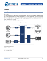
1.1 Kit Contents
This kit contains only the PSoC 4 Prototyping Kit, either the 4100 or 4200 series device.
Figure 1-1. PSoC 4 CY8CKIT-049-4xxx Prototyping Kit

CY8CKIT-049-4xxx PSoC 4 Prototyping Kit Guide, Doc. #: 001-90711 Rev. ** 8
Introduction
1.2 Getting Started
This user guide helps you to get acquainted with the PSoC 4 Prototyping Kit. The Software
Installation chapter on page 9 describes the installation of the PSoC Creator software. The Kit
Operation chapter on page 13 explains how to program the kit using a bootloader or a MiniProg3.
The Hardware chapter on page 28 details the hardware operation of the kit. The Example
Projects chapter on page 37 and USB-Serial Configuration chapter on page 51 walk you through
making projects and configuring the USB-Serial device on the kit. The Appendix on page 58 pro-
vides the schematics, pin assignment, and bill of materials (BOM).
1.3 Additional Learning Resources
For more information on PSoC, see the following links:
■ www.cypress.com/psoc
■ www.cypress.com/psoc4
■ www.cypress.com/psoccreator
■ www.cypress.com/CY8CKIT-049-41xx
■ www.cypress.com/CY8CKIT-049-42xx
■ www.cypress.com/CY8CKIT-042
■ www.cypress.com/go/usbserial
1.4 Technical Support
For assistance, go to our support web page, or contact our customer support:
Phone (USA): +1(800) 541-4736 extension 2
Phone (International): +1 (408) 943-2600, extension 2
1.5 Document Conventions
Table 1-1. Document Conventions for Guides
Convention Usage
Courier New Displays file locations, user entered text, and source code:
C:\...cd\icc\
Italics Displays file names and reference documentation:
Read about the sourcefile.hex file in the PSoC Designer User Guide.
[Bracketed, Bold] Displays keyboard commands in procedures:
[Enter] or [Ctrl] [C]
File > Open Represents menu paths:
File > Open > New Project
Bold Displays commands, menu paths, and icon names in procedures:
Click the File icon and then click Open.
Times New Roman Displays an equation:
2 + 2 = 4
Text in gray boxes Describes Cautions or unique functionality of the product.

CY8CKIT-049-4xxx PSoC 4 Prototyping Kit Guide, Doc. #: 001-90711 Rev. ** 9
2. Software Installation
2.1 Kit Software
The PSoC 4 Prototyping Kit does not require installation, but it is recommended that you install the
following content:
■ PSoC Creator™
■ EZ-USB Software Development Kit (SDK)
To install PSoC Creator, download the installer from the download table on the PSoC Creator web
page and install it.
1. Run the installer and select the folder to install the PSoC Creator files. Choose the directory and
click Next.
2. Select the Installation type and click Next.
Figure 2-1. PSoC Creator Installation
3. Accept the Software License Agreement. After the installation is complete, the software is avail-
able at the following location: <InstallDirectory>\Cypress\PSoC Creator\<version>.
4. To install the USB-Serial SDK, download the installer from the web page and run it.

CY8CKIT-049-4xxx PSoC 4 Prototyping Kit Guide, Doc. #: 001-90711 Rev. ** 10
Software Installation
5. Run the installer and select the folder to install the USB-Serial SDK files. Choose the directory
and click Next.
Figure 2-2. Select Installation Folder for PSoC Creator
6. Accept the Software License Agreement by selecting I Agree and then click Next.
After the installation is complete, the following software tools are installed on your computer:
■ USB-Serial Configuration Utility
■ USB-Serial Test Utility
2.2 Install Hardware
There is no additional hardware installation required for this kit.
2.3 Uninstall Software
To uninstall the software, do one of the following:
■ Go to Start > All Programs > Cypress > Cypress Update Manager > Cypress Update Man-
ager, and then select Uninstall.
■ Go to Start > Control Panel > Programs and Features, and then select the Uninstall/Change.

CY8CKIT-049-4xxx PSoC 4 Prototyping Kit Guide, Doc. #: 001-90711 Rev. ** 11
Software Installation
2.4 Open the PSoC 4 Code Example Project in PSoC Creator
1. Launch the PSoC Creator software from the Start menu.
Figure 2-3. PSoC Creator Start Page
2. Open the example project from the Start Page. Click File > Open > Project/Workspace, and
open the example project downloaded from the kit page.
Figure 2-4. Open Project/Workspace
The example project opens and displays the project files in the Workspace Explorer. The work-
space includes two sample projects linked in the Workspace Explorer. Subsequent sections of this
user guide show how to build, program, and understand the example projects supplied with this kit.

CY8CKIT-049-4xxx PSoC 4 Prototyping Kit Guide, Doc. #: 001-90711 Rev. ** 12
Software Installation
Figure 2-5. Workspace Explorer

CY8CKIT-049-4xxx PSoC 4 Prototyping Kit Guide, Doc. #: 001-90711 Rev. ** 13
3. Kit Operation
The PSoC 4 Prototyping Kit is simplistic in design and focuses on providing you with complete
access to develop applications using the PSoC 4 device family. The development kit supports a
number of onboard functions such as an LED, push button, through-hole connections, USB-Serial
connectivity to the PC, and a breakable board design to separate the two target boards.
Figure 3-1. PSoC 4 Prototyping Kit
3.1 Connecting the PSoC 4 Prototyping Kit to a Computer
To use the PSoC 4 Prototyping Kit, you need to connect the kit to a target PC. The kit is designed to
be connected to the computer through USB. The USB connector will provide power to the target
boards and enable serial communication. CY8CKIT-049-4xxx implements a PCB-based USB con-
nector that makes connections to the USB port when plugged in. The amber LED turns on when the
board is plugged into the port to indicate power.
Figure 3-2. Connecting the PSoC 4 Prototyping Kit to a Computer

CY8CKIT-049-4xxx PSoC 4 Prototyping Kit Guide, Doc. #: 001-90711 Rev. ** 14
Kit Operation
Figure 3-3. PSoC 4 Prototyping Kit Connected to the Computer
3.2 CY8CKIT-049-4xxx USB COM Port
When you connect CY8CKIT-049-4xxx to the PC over a USB interface, it enumerates as a COM port
device under the Device Manager window in Windows OS. Often, the COM port number will be
higher than any existing COM port value. For example, in the following image the CY8CKIT-049-
4xxx enumerates as COM37.
Figure 3-4. CY8CKIT-049-4xxx USB COM Port in Device Manager
When connecting your CY8CKIT-049-4xxx to a computer for the first time or to any new USB port, it
may take a moment to enumerate because the computer will complete an online check for the latest
drivers.
Figure 3-5. Automatic Driver Software Installation for CY8CKIT-049-4xxx

CY8CKIT-049-4xxx PSoC 4 Prototyping Kit Guide, Doc. #: 001-90711 Rev. ** 15
Kit Operation
Figure 3-6. Driver Software Installation Complete
3.2.1 Configuring the COM Port
Different USB COM devices are connected to different USB ports and the PC assigns COM port val-
ues to those devices. As more devices are connected, the COM port values will continue to
increase. Some applications require the COM port to be less than 10, such as ‘COM10’. In the fol-
lowing examples, the Bootloader Host utility requires a COM port number below 10.
To change the assigned COM port number, do the following:
1. Open the Device Manager from the Control Panel window.
Figure 3-7. Windows Device Manager
2. On the Device Manager window, under Ports (COM and LPT), right-click on the COM port cre-
ated by the CY8CKIT-049-4xxx kit and select Properties.

CY8CKIT-049-4xxx PSoC 4 Prototyping Kit Guide, Doc. #: 001-90711 Rev. ** 16
Kit Operation
Figure 3-8. Configuring COM Port for CY8CKIT-049-4xxx
3. Select the Port Settings tab and click the Advanced… button.
Figure 3-9. Configuring COM Port Settings for CY8CKIT-049-4xxx

CY8CKIT-049-4xxx PSoC 4 Prototyping Kit Guide, Doc. #: 001-90711 Rev. ** 17
Kit Operation
4. Click the COM Port Number drop-down menu and select an available COM port; click OK.
Some COM ports will have the indicator (in use). Select a port that does not have this identifier.
Figure 3-10. Configuring COM Port Settings for CY8CKIT-049-4xxx
The Device Manager window will then display the new COM port value. In the following image, the
value changed from COM37 to COM2.
Figure 3-11. Renamed COM Port for CY8CKIT-049-4xxx in Device Manager
3.3 Programming the CY8CKIT-049-4xxx Kit
The CY8CKIT-049-4xxx kits are pre-programmed with firmware containing a bootloader. Therefore,
there are two methods of programming the onboard PSoC 4 device:
1. Perform UART bootload programming of the PSoC 4 device using the USB-Serial device as a
USB-UART bridge.
2. Use a CY8CKIT-002 MiniProg3 to program and debug the target device directly.
Note that as long as the PSoC 4 device on the kit contains the bootloader, either method of program-
ming can be used. If a project without a bootloader is programmed onto the PSoC 4, then only the
second method may be used until the PSoC 4 device is reprogrammed with a bootloader. In other
words, any project can be programmed using the MiniProg3 programmer, but only a bootloadable
project can be bootloaded using the first method.
See the following sections for an example of a bootloader project and a bootloadable project. See
application note AN73854 for additional details on bootloading.

CY8CKIT-049-4xxx PSoC 4 Prototyping Kit Guide, Doc. #: 001-90711 Rev. ** 18
Kit Operation
3.3.1 Programming a CY8CKIT-049-4xxx Project Using MiniProg3
To use MiniProg3 for programming, connect wires or a 5-pin 100-mil spaced header to the program-
ming header on the CY8CKIT-049-4xxx board. The programming header is a 5-pin header indicated
on the silkscreen and is labeled ‘PROG’. This connector is oriented to mate directly with MiniProg3's
5-pin header. The CY8CKIT-049 supports both power cycle and reset programming modes.
Figure 3-12. Connecting CY8CKIT-049-4xxx to MiniProg3
Note: CY8CKIT-002 MiniProg3 is not part of the PSoC 4 Prototyping Kit contents and can be pur-
chased from the Cypress Online Store.
The following images show the pinout for MiniProg3 and the connections on CY8CKIT-049-4xxx.
Figure 3-13. Pinout for MiniProg3

CY8CKIT-049-4xxx PSoC 4 Prototyping Kit Guide, Doc. #: 001-90711 Rev. ** 19
Kit Operation
Figure 3-14. CY8CKIT-049-4xxx Connections for MiniProg3
The code examples described in this section show how to bootload new projects into PSoC 4 and
create bootloader and bootloadable projects. To access the kit examples, download the examples
from the kit web page.
The initial example shows how to program the kit with just a bootloader using MiniProg3. Note that
the kit is pre-programmed with a project containing a bootloader, so this step is not necessary to
change the application firmware.
1. Launch PSoC Creator from the Start menu.
Figure 3-15. PSoC Creator Start Page
2. Open the example project workspace from the Start Page. Select File > Open > Project/Work-
space.
3. Open the workspace by navigating to the example downloaded from the kit page.

CY8CKIT-049-4xxx PSoC 4 Prototyping Kit Guide, Doc. #: 001-90711 Rev. ** 20
Kit Operation
Figure 3-16. Opening the Project in PSoC Creator
The example opens and displays the project files in the Workspace Explorer. The workspace
includes two sample projects linked in the Workspace Explorer - a bootloader project and a boot-
loadable project.
4. Right-click the UART_Bootloader project and select Set As Active Project.
Figure 3-17. Setting Example Project as Active Project in Workspace Explorer
5. Select Build > Build UART_Bootloader.
Figure 3-18. Building the Project
6. Connect MiniProg3 to the CY8CKIT-049-4xxx prototyping board.
7. Select Debug > Program.
Page is loading ...
Page is loading ...
Page is loading ...
Page is loading ...
Page is loading ...
Page is loading ...
Page is loading ...
Page is loading ...
Page is loading ...
Page is loading ...
Page is loading ...
Page is loading ...
Page is loading ...
Page is loading ...
Page is loading ...
Page is loading ...
Page is loading ...
Page is loading ...
Page is loading ...
Page is loading ...
Page is loading ...
Page is loading ...
Page is loading ...
Page is loading ...
Page is loading ...
Page is loading ...
Page is loading ...
Page is loading ...
Page is loading ...
Page is loading ...
Page is loading ...
Page is loading ...
Page is loading ...
Page is loading ...
Page is loading ...
Page is loading ...
Page is loading ...
Page is loading ...
Page is loading ...
Page is loading ...
Page is loading ...
Page is loading ...
Page is loading ...
Page is loading ...
Page is loading ...
Page is loading ...
/