Page is loading ...


Copyrights
CY8CKIT-049-4xxx PSoC® 4 Prototyping Kit Guide, Doc. #: 001-90711 Rev. *J 2
Copyrights
© Cypress Semiconductor Corporation, 2014-2018. This document is the property of Cypress Semi-
conductor Corporation and its subsidiaries, including Spansion LLC ("Cypress"). This document,
including any software or firmware included or referenced in this document ("Software"), is owned by
Cypress under the intellectual property laws and treaties of the United States and other countries
worldwide. Cypress reserves all rights under such laws and treaties and does not, except as specifi-
cally stated in this paragraph, grant any license under its patents, copyrights, trademarks, or other
intellectual property rights. If the Software is not accompanied by a license agreement and you do
not otherwise have a written agreement with Cypress governing the use of the Software, then
Cypress hereby grants you a personal, non-exclusive, nontransferable license (without the right to
sublicense) (1) under its copyright rights in the Software (a) for Software provided in source code
form, to modify and reproduce the Software solely for use with Cypress hardware products, only
internally within your organization, and (b) to distribute the Software in binary code form externally to
end users (either directly or indirectly through resellers and distributors), solely for use on Cypress
hardware product units, and (2) under those claims of Cypress's patents that are infringed by the
Software (as provided by Cypress, unmodified) to make, use, distribute, and import the Software
solely for use with Cypress hardware products. Any other use, reproduction, modification, transla-
tion, or compilation of the Software is prohibited.
TO THE EXTENT PERMITTED BY APPLICABLE LAW, CYPRESS MAKES NO WARRANTY OF
ANY KIND, EXPRESS OR IMPLIED, WITH REGARD TO THIS DOCUMENT OR ANY SOFTWARE
OR ACCOMPANYING HARDWARE, INCLUDING, BUT NOT LIMITED TO, THE IMPLIED WAR-
RANTIES OF MERCHANTABILITY AND FITNESS FOR A PARTICULAR PURPOSE. To the extent
permitted by applicable law, Cypress reserves the right to make changes to this document without
further notice. Cypress does not assume any liability arising out of the application or use of any prod-
uct or circuit described in this document. Any information provided in this document, including any
sample design information or programming code, is provided only for reference purposes. It is the
responsibility of the user of this document to properly design, program, and test the functionality and
safety of any application made of this information and any resulting product. Cypress products are
not designed, intended, or authorized for use as critical components in systems designed or
intended for the operation of weapons, weapons systems, nuclear installations, life-support devices
or systems, other medical devices or systems (including resuscitation equipment and surgical
implants), pollution control or hazardous substances management, or other uses where the failure of
the device or system could cause personal injury, death, or property damage ("Unintended Uses"). A
critical component is any component of a device or system whose failure to perform can be reason-
ably expected to cause the failure of the device or system, or to affect its safety or effectiveness.
Cypress is not liable, in whole or in part, and you shall and hereby do release Cypress from any
claim, damage, or other liability arising from or related to all Unintended Uses of Cypress products.
You shall indemnify and hold Cypress harmless from and against all claims, costs, damages, and
other liabilities, including claims for personal injury or death, arising from or related to any Unin-
tended Uses of Cypress products.
Cypress, the Cypress logo, Spansion, the Spansion logo, and combinations thereof, PSoC,
CapSense, EZ-USB, F-RAM, and Traveo are trademarks or registered trademarks of Cypress in the
United States and other countries. For a more complete list of Cypress trademarks, visit
cypress.com. Other names and brands may be claimed as property
of their respective owners.

CY8CKIT-049-4xxx PSoC® 4 Prototyping Kit Guide, Doc. #: 001-90711 Rev. *J 3
Contents
Safety Information 5
1. Introduction 7
1.1 Kit Contents .................................................................................................................7
1.2 Getting Started.............................................................................................................8
1.3 Additional Learning Resources....................................................................................8
1.3.1 PSoC Creator...................................................................................................9
1.3.2 PSoC Creator Code Examples ......................................................................10
1.3.3 PSoC Creator Help ........................................................................................11
1.3.4 Technical Support...........................................................................................12
1.4 Document Conventions .............................................................................................12
2. Software Installation 13
2.1 Before You Begin.......................................................................................................13
2.2 CY8CKIT-049-41xx/CY8CKIT-049-42xx Software ....................................................13
2.3 Install Software ..........................................................................................................14
2.4 Install Hardware.........................................................................................................14
2.5 Uninstall Software......................................................................................................14
2.6 Open the “PSoC 4 Code” Code Example in PSoC Creator.......................................15
3. Kit Operation 16
3.1 Connecting the PSoC 4 Prototyping Kit to a Computer .............................................16
3.2 CY8CKIT-049-4xxx USB COM Port ..........................................................................17
3.3 Programming a CY8CKIT-049-4xxx Project Using the Bootloader ...........................18
3.4 USB-UART Default Settings ......................................................................................25
4. Hardware 26
4.1 Board Details .............................................................................................................26
4.2 Theory of Operation...................................................................................................27
4.3 Functional Description ...............................................................................................27
4.3.1 Power Supply System ....................................................................................27
4.3.2 Board Separation (Snapping).........................................................................28
4.3.3 Header Connections ......................................................................................28
4.3.4 User and Passive Inputs ................................................................................32

CY8CKIT-049-4xxx PSoC® 4 Prototyping Kit Guide, Doc. #: 001-90711 Rev. *J 4
Contents
5. Code Examples 35
5.1 Bootloader Base Code Example................................................................................35
5.2 Bootloadable Code Example .....................................................................................36
5.3 Creating a New Bootloadable Project........................................................................37
5.4 Converting a Non-bootloadable Project to a Bootloadable Project............................40
5.4.1 PWMExample ................................................................................................41
5.4.2 Entering Bootloader Mode from the Bootloadable Application.......................49
6. USB-Serial Configuration 53
6.1 USB-Serial Resources...............................................................................................53
6.2 USB-Serial Configuration Utility.................................................................................54
6.2.1 Connecting to a USB-Serial Device ...............................................................55
6.2.2 Configuring a Serial Port ................................................................................56
6.2.3 Configuring GPIOs .........................................................................................59
6.2.4 Additional Features of the USB-Serial Device ...............................................61
A. Appendix 62
A.1 CY8CKIT-049-4xxx Schematics ................................................................................62
A.2 Programming a CY8CKIT-049-4xxx Project Using MiniProg3...................................69
A.3 Bill of Materials ..........................................................................................................74
Revision History 75

CY8CKIT-049-4xxx PSoC® 4 Prototyping Kit Guide, Doc. #: 001-90711 Rev. *J 5
Safety Information
Regulatory Compliance
The CY8CKIT-049-4xxx Prototyping Kit is intended for use as a development platform for hardware
or software in a laboratory environment. The board is an open system design, which does not
include a shielded enclosure. This may cause interference to other electrical or electronic devices in
close proximity. In a domestic environment, this product may cause radio interference. In such
cases, you may be required to take adequate preventive measures. In addition, this board should
not be used near any medical equipment or RF devices.
Attaching additional wiring to this product or modifying the product operation from the factory default
may affect its performance and cause interference with other apparatus in the immediate vicinity. If
such interference is detected, suitable mitigating measures should be taken.
The CY8CKIT-049-4xxx Prototyping Kit, as shipped from the factory, has been verified to meet with
requirements of CE as a Class A product.
The CY8CKIT-049-4xxx contains electrostatic discharge
(ESD) sensitive devices. Electrostatic charges readily
accumulate on the human body and any equipment, and
can discharge without detection. Permanent damage may
occur on devices subjected to high-energy discharges.
Proper ESD precautions are recommended to avoid
performance degradation or loss of functionality. Store
unused CY8CKIT-049-4xxx boards in the protective
shipping package.
End-of-Life/Product Recycling
This kit has an end-of life five years from the date of
manufacture mentioned on the back of the box. Contact your
nearest recycler for discarding the kit.

CY8CKIT-049-4xxx PSoC® 4 Prototyping Kit Guide, Doc. #: 001-90711 Rev. *J 6
Safety Information
General Safety Instructions
ESD Protection
ESD can damage boards and associated components. Cypress recommends that you perform
procedures only at an ESD workstation. If such a workstation is not available, use appropriate ESD
protection by wearing an antistatic wrist strap attached to the chassis ground (any unpainted metal
surface) on your board when handling parts.
Handling Boards
CY8CKIT-049-4xxx boards are sensitive to ESD. Hold the board only by its edges. After removing
the board from its box, place it on a grounded, static-free surface. Use a conductive foam pad if
available. Do not slide board over any surface.

CY8CKIT-049-4xxx PSoC® 4 Prototyping Kit Guide, Doc. #: 001-90711 Rev. *J 7
1. Introduction
Thank you for your interest in the PSoC
®
4 CY8CKIT-049-4xxx family of prototyping kits. The
prototyping kit is designed as an easy-to-use and inexpensive prototyping platform for users wishing
to rapidly develop products using the PSoC 4 families and use the unique flexibility of the PSoC 4
architecture. Designed for flexibility, these kits offer an open footprint breakout board to maximize
the end utility of the PSoC 4 device. These kits provide a low-cost alternative to device samples
while providing a platform to easily develop and integrate the PSoC 4 device into your end system.
In addition, the board includes the following features:
■ Onboard CMOD capacitors to enable CapSense
®
development
■ A bypass capacitor to ensure the high quality ADC conversions
■ An LED to provide feedback
■ A push button to provide a simple user input and trigger the bootloader programming mode
■ The CY8CKIT-049-41xx PSoC 4 Prototyping kit has CY8C4125AXI-483 device on-board and
CY8CKIT-049-42xx PSoC 4 Prototyping kit has CY8C4245AXI-483 device on-board
The CY8CKIT-049-4xxx development kit also supports the Cypress USB-Serial CY7C65211
Full-Speed USB controller that enables PC connectivity and serial interfaces, such as USB-UART,
USB-I2C, USB-SPI, and USB-GPIO. The development kit includes a Cypress USB-Serial controller
used to bootload the target PSoC 4 device. The PSoC 4 prototyping board is breakable, allowing
you to separate the USB-Serial board from the PSoC 4 board.
This kit supports either 5 V or 3.3 V power supply voltages. The device can be programmed using
the bootloader or the Cypress MiniProg3 programmer. The PSoC 4 Prototyping Kit supports boards
based on the 4100 and 4200 device families, delivering a programmable platform for a wide range of
embedded applications at a very low cost. The PSoC 4 is a scalable and reconfigurable platform
architecture for a family of mixed-signal programmable embedded system controllers with an ARM
®
Cortex™-M0 CPU. It combines programmable and reconfigurable analog and digital blocks with
flexible automatic routing.
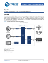
1.1 Kit Contents
This kit contains only the PSoC 4 Prototyping Kit, either the 4100 or 4200 series device.
Figure 1-1. PSoC 4 CY8CKIT-049-4xxx Prototyping Kit

CY8CKIT-049-4xxx PSoC® 4 Prototyping Kit Guide, Doc. #: 001-90711 Rev. *J 8
Introduction
1.2 Getting Started
This user guide helps you to get acquainted with the PSoC 4 Prototyping Kit. The Software
Installation chapter on page 13 describes the installation of the PSoC Creator software. The Kit
Operation chapter on page 16 explains how to program the kit using a bootloader or a MiniProg3.
The Hardware chapter on page 26 details the hardware operation of the kit. The Code
Examples chapter on page 35 and USB-Serial Configuration chapter on page 53 walk you through
making projects and configuring the USB-Serial device on the kit. The Appendix on page 62
provides the schematics, pin assignment, and bill of materials (BOM).
1.3 Additional Learning Resources
Cypress provides a wealth of data at www.cypress.com to help you to select the right PSoC device
for your design, and to help you to quickly and effectively integrate the device into your design. For a
comprehensive list of resources, see KBA86521, How to Design with PSoC 3, PSoC 4, and
PSoC 5LP. The following is an abbreviated list for PSoC 4:
■ Overview: PSoC Portfolio, PSoC Roadmap
■ Product Selectors: PSoC 1, PSoC 3, PSoC 4, or PSoC 5LP. In addition, PSoC Creator includes
a device selection tool.
■ Datasheets: Describe and provide electrical specifications for the PSoC 4000, PSoC 4100, and
PSoC 4200 device families.
■ CapSense Design Guide: Learn how to design capacitive touch-sensing applications with the
PSoC 4 family of devices.
■ Application Notes and Code Examples: Cover a broad range of topics, from basic to advanced
level. Many of the application notes include code examples. Visit the PSoC 3/4/5 Code Examples
webpage for a list of all available PSoC Creator code examples. For accessing code examples
from within PSoC Creator – see PSoC Creator Code Examples on page 10. These code
examples available across PSoC Creator, Application notes and kits for the most part will NOT be
bootloadable. However, with a very small modification you can port them to a bootloadable
project and use them with the CY8CKIT-049. Refer to Converting a Non-bootloadable Project to
a Bootloadable Project on page 40 for details.
■ Technical Reference Manuals (TRM): Provide detailed descriptions of the architecture and
registers in each PSoC 4 device family.
■ Development Kits:
❐ CY8CKIT-042 and CY8CKIT-040, PSoC 4 Pioneer Kits, are easy-to-use and inexpensive
development platforms. These kits include connectors for Arduino™ compatible shields and
Digilent
®
Pmod™ daughter cards.
❐ CY8CKIT-049 is a very low-cost prototyping platform for sampling PSoC 4 devices.
❐ CY8CKIT-001 is a common development platform for all PSoC family devices.
■ The MiniProg3 device provides an interface for flash programming and debug.
■ Knowledge Base Articles (KBA): Provide design and application tips from experts on the
devices/kits. For instance, KBA93541, explains how to use CY8CKIT-049 to program another
PSoC 4.

CY8CKIT-049-4xxx PSoC® 4 Prototyping Kit Guide, Doc. #: 001-90711 Rev. *J 9
Introduction
1.3.1 PSoC Creator
PSoC Creator is a free Windows-based Integrated Design Environment (IDE). It enables concurrent
hardware and firmware design of systems based on PSoC 3, PSoC 4, and PSoC 5LP. See
Figure 1-2 – with PSoC Creator, you can:
1. Drag and drop Components to build your hardware system design in the main design workspace
2. Codesign your application firmware with the PSoC hardware
3. Configure Components using configuration tools
4. Explore the library of 100+ Components
5. Review Component datasheets
Figure 1-2. PSoC Creator Features
Visit PSoC Creator training page for video tutorials on learning and using PSoC Creator.

CY8CKIT-049-4xxx PSoC® 4 Prototyping Kit Guide, Doc. #: 001-90711 Rev. *J 10
Introduction
1.3.2 PSoC Creator Code Examples
PSoC Creator includes a large number of code example projects. These projects are available from
the PSoC Creator Start Page, as Figure 1-3 shows.
Example projects can speed up your design process by starting you off with a complete design,
instead of a blank page. The example projects also show how PSoC Creator Components can be
used for various applications. Code examples and datasheets are included, as Figure 1-4 on
page 11 shows.
In the Find Example Project dialog shown in Figure 1-4 on page 11, you have several options:
■ Filter for examples based on architecture or device family, i.e., PSoC 3, PSoC 4 or PSoC 5LP;
category; or keyword
■ Select from the menu of examples offered based on the Filter Options
■ Review the datasheet for the selection (on the Documentation tab)
■ Review the code example for the selection. You can copy and paste code from this window to
your project, which can help speed up code development, or
■ Create a new project (and a new workspace if needed) based on the selection. This can speed
up your design process by starting you off with a complete, basic design. You can then adapt that
design to your application.
Figure 1-3. Code Examples in PSoC Creator

CY8CKIT-049-4xxx PSoC® 4 Prototyping Kit Guide, Doc. #: 001-90711 Rev. *J 11
Introduction
Figure 1-4. Code Example Projects, with Sample Code
1.3.3 PSoC Creator Help
Visit the PSoC Creator home page to download the latest version of PSoC Creator. Then, launch
PSoC Creator and navigate to the following items:
■ Quick Start Guide: Choose Help > Documentation > Quick Start Guide. This guide gives you
the basics for developing PSoC Creator projects.
■ Simple Component example projects: Choose File > Open > Example projects. These
example projects demonstrate how to configure and use PSoC Creator Components.
■ Starter designs: Choose File > New > Project > PSoC 4 Starter Designs. These starter
designs demonstrate the unique features of PSoC 4.
■ System Reference Guide: Choose Help > System Reference > System Reference Guide.
This guide lists and describes the system functions provided by PSoC Creator.
■ Component datasheets: Right-click a Component and select “Open Datasheet.” Visit the
PSoC 4 Component Datasheets page for a list of all PSoC 4 Component datasheets.
■ Document Manager: PSoC Creator provides a document manager to help you to easily find and
review document resources. To open the document manager, choose the menu item Help >
Document Manager.

CY8CKIT-049-4xxx PSoC® 4 Prototyping Kit Guide, Doc. #: 001-90711 Rev. *J 12
Introduction
1.3.4 Technical Support
If you have any questions, our technical support team is happy to assist you. You can create a sup-
port request on the Cypress Technical Support page.
If you are in the United States, you can talk to our technical support team by calling our toll-free num-
ber: +1-800-541-4736. Select option 2 at the prompt.
You can also use the following support resources if you need quick assistance.
■ Self-help.
■ Local Sales Office Locations.
1.4 Document Conventions
Table 1-1. Document Conventions for Guides
Convention Usage
Courier New Displays file locations, user entered text, and source code:
C:\...cd\icc\
Italics Displays file names and reference documentation:
Read about the sourcefile.hex file in the PSoC Creator User Guide.
[Bracketed, Bold] Displays keyboard commands in procedures:
[Enter] or [Ctrl] [C]
File > Open Represents menu paths:
File > Open > New Project
Bold Displays commands, menu paths, and icon names in procedures:
Click the File icon and then click Open.
Times New Roman Displays an equation:
2 + 2 = 4
Text in gray boxes Describes Cautions or unique functionality of the product.

CY8CKIT-049-4xxx PSoC® 4 Prototyping Kit Guide, Doc. #: 001-90711 Rev. *J 13
2. Software Installation
2.1 Before You Begin
All Cypress software installations require administrator privileges, but these are not required to run
the software after it is installed. Close any other Cypress software that is currently running before
installing the kit software.
Note: The kit contents are installed in the C:\Program Files\Cypress folder by default. If the
Code examples are being run from the default install location, administrator privileges are required. If
you do not have administrator privileges, copy the Firmware folder from the default install location to
any other location on your PC and access the files
2.2 CY8CKIT-049-41xx/CY8CKIT-049-42xx Software
The kit requires Cypress' proprietary software, such as PSoC Creator, PSoC Programmer and the
USB-Serial Configuration Utility, and generic software such as .NET Framework, Windows Installer,
and Internet Explorer. The kit software is available on the kit web page in three formats:
Note: The USB-Serial Configuration Utility requires Visual C++. If Visual C++ is not installed in the
PC, the installer provides link to install the Visual C++ Redistributable package in the PC.
Table 2-1. Kit Software Formats
Install Package File Format Usage
CY8CKIT-049-41xx_Kit ISO/
CY8CKIT-049-42xx_Kit ISO
ISO
This package can be used if the PC does not have any
Cypress or non-Cypress prerequisite software installed. It first
installs the prerequisites and then the kit content (firmware,
hardware, and documentation files) in the specified location.
CY8CKIT-049-41xx_Kit Setup/
CY8CKIT-049-42xx_Kit Setup
EXE
This package can be used if the PC does not have any
Cypress prerequisite software installed. If any non-Cypress
prerequisites are found to be missing during installation, the
installer provides links to download and install them and then
installs the kit content (firmware, hardware, and
documentation files) in the specified location.
CY8CKIT-049-41xx_Kit Only/
CY8CKIT-049-42xx_Kit Only
EXE
This package can be used if the PC has all the Cypress and
non-Cypress prerequisites installed. It installs only the kit
content (firmware, hardware, and documentation files) in the
specified location. If any of the prerequisites are found
missing during the installation process, the installer prompts
you to install all the required software before attempting to
install the kit. The installer redirects to the kit web page to
download and install any missing Cypress software. Similarly,
it provides links to download and install the missing non-
Cypress prerequisites.

CY8CKIT-049-4xxx PSoC® 4 Prototyping Kit Guide, Doc. #: 001-90711 Rev. *J 14
Software Installation
Note: Adobe Reader is required to view kit documents. If Adobe Reader is not installed on your PC,
the installer provides the link to download and install it.
Note: PSoC Creator is provided with a free Keil C licence that has to be registered within 30 days of
installing PSoC Creator. To register your Keil license, you will require an internet connection. Please
read http://www.cypress.com/?id=4&rID=38519 for more details. Please read
http://www.cypress.com/?id=4&rID=44355 if PSoC Creator needs to be used on a PC that does not
have internet connection. The product ID for the Keil compiler is IKA1P-M6Q0E-8W7ST.
2.3 Install Software
1. Run cyautorun.exe in the kit ISO to start the installation process.
2. Click Install CY8CKIT-049-41xx to start CY8CKIT-049-41xx PSoC 4 Prototyping kit installation.
Click Install CY8CKIT-049-42xx to start CY8CKIT-049-42xx PSoC 4 Prototyping kit installation.
3. Select the folder to install the kit files. Choose the directory and click Next. The installation
directory is referred to as <Install_Directory> in this document.
4. When you click Next, the kit installer automatically installs the required software, if it is not
present on your computer.
5. Select the installation type in the Product Installation Overview window. The drop-down menu
contains three options: Typical (installs all the required features), Custom (lets you choose the
features to be installed), and Complete (installs all the contents). Click Next after you select the
installation type.
Note: It is recommended that you choose the Complete installation type.
6. Read and Accept the End-User License Agreement and click Next to proceed with the
installation.
7. When the installation begins, a list of packages appears on the installation page. A green check
mark appears adjacent to every package after successful installation.
8. After installing all the packages, the CyInstaller finish page opens up. Please provide the
requested contact information or uncheck the “Continue Without Contact Information” checkbox
and click on Finish button to complete the kit installation.
After the installation is complete, the kit contents are available at the following location:
1. For CY8CKIT-049-41xx: <Install_Directory>\ CY8CKIT-049-41xx \<version>
2. For CY8CKIT-049-42xx: <Install_Directory>\ CY8CKIT-049-42xx \<version>
2.4 Install Hardware
There is no additional hardware installation required for this kit.
2.5 Uninstall Software
To uninstall the software, do one of the following:
■ Go to Start > All Programs > Cypress > Cypress Update Manager > Cypress Update
Manager, and then select the Uninstall button corresponding to the kit software.
■ Go to Start > Control Panel > Programs and Features, and then select the Uninstall/Change
button corresponding to the kit software.

CY8CKIT-049-4xxx PSoC® 4 Prototyping Kit Guide, Doc. #: 001-90711 Rev. *J 15
Software Installation
2.6 Open the “PSoC 4 Code” Code Example in PSoC Creator
Note: The code examples require administrator privileges if they are run directly from the default
install location (C:\Program Files\Cypress). If you do not have administrator privileges, copy the
Firmware folder from the default install location to any other location on your PC and use the files.
1. Launch the PSoC Creator software from the Start menu.
Figure 2-1. PSoC Creator Start Page
2. Open the SCB_Bootloader.cywrk workspace by choosing File > Open > Project/Workspace
and navigating to the directory in which your project is present.
Figure 2-2. Open Project/Workspace
The workspace includes two sample projects linked in the Workspace Explorer. Subsequent
chapters of this user guide show how to build, program, and understand the code examples supplied
with this kit.

CY8CKIT-049-4xxx PSoC® 4 Prototyping Kit Guide, Doc. #: 001-90711 Rev. *J 16
3. Kit Operation
The PSoC 4 Prototyping Kit is simplistic in design and focuses on providing you with complete
access to develop applications using the PSoC 4 device family. The development kit supports a
number of onboard functions such as an LED, push button, through-hole connections, USB-Serial
connectivity to the PC, and a breakable board design to separate the two target boards.
Figure 3-1. PSoC 4 Prototyping Kit
3.1 Connecting the PSoC 4 Prototyping Kit to a Computer
To use the PSoC 4 Prototyping Kit, you need to connect the kit to a target PC. The kit is designed to
be connected to the computer through USB. The USB connector will provide power to the target
boards and enable serial communication. CY8CKIT-049-4xxx implements a PCB-based USB
connector that makes connections to the USB port when plugged in. The amber LED turns on when
the board is plugged into the port to indicate power.
Figure 3-2. Connecting the PSoC 4 Prototyping Kit to a Computer
6
1. PCB USB Connector (J8)
2. USB-Serial Bridge Controller (U2)
3. Power LED (LED2)
4. Current Measurement Jumper (J4)
5. User LED (LED1)
6. PSoC 4 (U1)
7. Programming Header
8. Push button (SW1)
2 4 78531

CY8CKIT-049-4xxx PSoC® 4 Prototyping Kit Guide, Doc. #: 001-90711 Rev. *J 17
Kit Operation
Figure 3-3. PSoC 4 Prototyping Kit Connected to the Computer
3.2 CY8CKIT-049-4xxx USB COM Port
When you connect the CY8CKIT-049-4xxx to the PC over a USB interface, it enumerates as a COM
port device under the Device Manager window on the Windows OS. Often, the COM port number will
be higher than any existing COM port value. For example, in the following image the
CY8CKIT-049-4xxx enumerates as COM37.
Figure 3-4. CY8CKIT-049-4xxx USB COM Port in Device Manager
When connecting your CY8CKIT-049-4xxx to a computer for the first time or to any new USB port, it
may take a moment to enumerate because the computer will complete an online check for the latest
drivers.
Figure 3-5. Automatic Driver Software Installation for CY8CKIT-049-4xxx

CY8CKIT-049-4xxx PSoC® 4 Prototyping Kit Guide, Doc. #: 001-90711 Rev. *J 18
Kit Operation
Figure 3-6. Driver Software Installation Complete
Note: The baud rate settings do not apply to the virtual COM port as the data transmission is taking
place using the Full-Speed USB bus at 12 Mbps. However, because of the virtual COM port driver
that sits between the PC and the USB-Serial device, the operating system will see the device as a
normal serial port and you will be able to set the baud rate. However, these settings may be ignored.
3.3 Programming a CY8CKIT-049-4xxx Project Using the Bootloader
The following example shows how to bootload (program) a project into the PSoC 4 with the
USB-Serial device, using the Bootloader Host. To use this method, the PSoC 4 device must contain
the bootloader and the project must be configured as bootloadable. This is the default programming
method for new users.
The following steps use the code example included in the kit installer.
1. Launch PSoC Creator from the Start menu.

CY8CKIT-049-4xxx PSoC® 4 Prototyping Kit Guide, Doc. #: 001-90711 Rev. *J 19
Kit Operation
2. Open the SCB_Bootloader.cywrk workspace from Examples and Kits > Kits. Select
CY8CKIT-049-41xx folder for CY8CKIT-049-41xx PSoC 4 Prototyping Kit and
CY8CKIT-049-42xx folder for CY8CKIT-049-42xx PSoC 4 Prototyping Kit.
3. Select the folder where you want to save the project and click OK.
Figure 3-7. Open the Project

CY8CKIT-049-4xxx PSoC® 4 Prototyping Kit Guide, Doc. #: 001-90711 Rev. *J 20
Kit Operation
4. Click on Build > Build All Projects.
Note: The UART_Bootloader project is a dependency for the Bootloadable Blinking LED project.
Hence, both example projects must be built by selecting Build > Build All Projects.
5. In the Workspace Explorer, right-click the Bootloadable Blinking LED project and select Set As
Active Project.
Figure 3-8. Set the Code Example as Active Project
The bootloadable project must be associated with the bootloader project's HEX and ELF files.
This will ensure that the firmware code mapping aligns with the code on the target device.
6. Under the 'Bootloadable Blinking LED' code example, double-click the 'TopDesign.cysch' file to
open the schematic view. Select the tab for the Bootloadable Project schematic page if it is not
already selected.
Figure 3-9. Open Schematic View
/