Page is loading ...


CY8CKIT-044 PSoC® 4 M-Series Pioneer Kit Guide, Doc. No. 001-96598 Rev. *C 2
Copyrights
© Cypress Semiconductor Corporation, 2015-2017. This document is the property of Cypress Semiconductor
Corporation and its subsidiaries, including Spansion LLC (“Cypress”). This document, including any software or firmware
included or referenced in this document (“Software”), is owned by Cypress under the intellectual property laws and treaties
of the United States and other countries worldwide. Cypress reserves all rights under such laws and treaties and does not,
except as specifically stated in this paragraph, grant any license under its patents, copyrights, trademarks, or other
intellectual property rights. If the Software is not accompanied by a license agreement and you do not otherwise have a
written agreement with Cypress governing the use of the Software, then Cypress hereby grants you a personal, non-
exclusive, nontransferable license (without the right to sublicense) (1) under its copyright rights in the Software (a) for
Software provided in source code form, to modify and reproduce the Software solely for use with Cypress hardware
products, only internally within your organization, and (b) to distribute the Software in binary code form externally to end
users (either directly or indirectly through resellers and distributors), solely for use on Cypress hardware product units, and
(2) under those claims of Cypress’s patents that are infringed by the Software (as provided by Cypress, unmodified) to
make, use, distribute, and import the Software solely for use with Cypress hardware products. Any other use, reproduction,
modification, translation, or compilation of the Software is prohibited.
TO THE EXTENT PERMITTED BY APPLICABLE LAW, CYPRESS MAKES NO WARRANTY OF ANY KIND, EXPRESS
OR IMPLIED, WITH REGARD TO THIS DOCUMENT OR ANY SOFTWARE OR ACCOMPANYING HARDWARE,
INCLUDING, BUT NOT LIMITED TO, THE IMPLIED WARRANTIES OF MERCHANTABILITY AND FITNESS FOR A
PARTICULAR PURPOSE. To the extent permitted by applicable law, Cypress reserves the right to make changes to this
document without further notice. Cypress does not assume any liability arising out of the application or use of any product
or circuit described in this document. Any information provided in this document, including any sample design information
or programming code, is provided only for reference purposes. It is the responsibility of the user of this document to
properly design, program, and test the functionality and safety of any application made of this information and any resulting
product. Cypress products are not designed, intended, or authorized for use as critical components in systems designed or
intended for the operation of weapons, weapons systems, nuclear installations, life-support devices or systems, other
medical devices or systems (including resuscitation equipment and surgical implants), pollution control or hazardous
substances management, or other uses where the failure of the device or system could cause personal injury, death, or
property damage (“Unintended Uses”). A critical component is any component of a device or system whose failure to
perform can be reasonably expected to cause the failure of the device or system, or to affect its safety or effectiveness.
Cypress is not liable, in whole or in part, and you shall and hereby do release Cypress from any claim, damage, or other
liability arising from or related to all Unintended Uses of Cypress products. You shall indemnify and hold Cypress harmless
from and against all claims, costs, damages, and other liabilities, including claims for personal injury or death, arising from
or related to any Unintended Uses of Cypress products.
Cypress, the Cypress logo, Spansion, the Spansion logo, and combinations thereof, WICED, PSoC, CapSense, EZ-USB,
F-RAM, and Traveo are trademarks or registered trademarks of Cypress in the United States and other countries. For a
more complete list of Cypress trademarks, visit cypress.com. Other names and brands may be claimed as property of their
respective owners.

CY8CKIT-044 PSoC® 4 M-Series Pioneer Kit Guide, Doc. No. 001-96598 Rev. *C 3
Contents
Safety Information .................................................................................................................................................................. 6
General Safety Instructions ............................................................................................................................................. 6
1. Introduction .................................................................................................................................................................... 7
1.1 Kit Contents ........................................................................................................................................................... 7
1.2 Board Details ......................................................................................................................................................... 8
1.3 PSoC Creator ...................................................................................................................................................... 10
1.3.1 PSoC Creator Code Examples ............................................................................................................... 11
1.3.2 Kit Example Projects ............................................................................................................................... 12
1.3.3 PSoC Creator Help ................................................................................................................................. 12
1.4 Getting Started .................................................................................................................................................... 12
1.5 Additional Learning Resources ............................................................................................................................ 12
1.6 Technical Support ................................................................................................................................................ 13
1.7 Document Conventions ....................................................................................................................................... 13
1.8 Acronyms ............................................................................................................................................................ 14
2. Installation.................................................................................................................................................................... 15
2.1 Before You Begin ................................................................................................................................................ 15
2.2 Install Software .................................................................................................................................................... 15
2.3 Uninstall Software ................................................................................................................................................ 17
3. Kit Operation ................................................................................................................................................................ 18
3.1 Theory of Operation ............................................................................................................................................. 18
3.2 KitProg ................................................................................................................................................................. 21
3.3 Programming and Debugging PSoC 4200M Device ............................................................................................ 21
3.3.1 Programming using PSoC Creator ......................................................................................................... 21
3.3.2 Debugging using PSoC Creator ............................................................................................................. 22
3.3.3 Programming using PSoC Programmer ................................................................................................. 22
3.4 USB-UART Bridge ............................................................................................................................................... 22
3.5 USB-I2C Bridge ................................................................................................................................................... 22
3.6 Mass Storage Programmer.................................................................................................................................. 22
3.7 Updating the KitProg Firmware ............................................................................................................................ 22
4. Example Projects ......................................................................................................................................................... 23
4.1 Using the Kit Example Projects ........................................................................................................................... 23
4.2 Using the Micrium® µC/Probe™ Projects ............................................................................................................ 25
4.3 Deep-Sleep Blinky ............................................................................................................................................... 25

Contents
CY8CKIT-044 PSoC® 4 M-Series Pioneer Kit Guide, Doc. No. 001-96598 Rev. *C 4
4.3.1 Project Description .................................................................................................................................. 25
4.3.2 Hardware Connections ........................................................................................................................... 25
4.3.3 Verify Output ........................................................................................................................................... 25
4.4 CapSense Proximity ............................................................................................................................................ 26
4.4.1 Project Description .................................................................................................................................. 26
4.4.2 Hardware Connections ........................................................................................................................... 26
4.4.3 Verify Output ........................................................................................................................................... 26
4.5 Proximity Gestures .............................................................................................................................................. 27
4.5.1 Project Description .................................................................................................................................. 27
4.5.2 Hardware Connections ........................................................................................................................... 29
4.5.3 Verify Output ........................................................................................................................................... 29
4.6 Touch Gestures ................................................................................................................................................... 30
4.6.1 Project Description .................................................................................................................................. 30
4.6.2 Hardware Connections ........................................................................................................................... 32
4.6.3 Verify Output ........................................................................................................................................... 32
4.7 Accelerometer ..................................................................................................................................................... 33
4.7.1 Project Description .................................................................................................................................. 33
4.7.2 Hardware Connections ........................................................................................................................... 34
4.7.3 Verify Output ........................................................................................................................................... 34
4.8 Sensor Hub.......................................................................................................................................................... 34
4.8.1 Project Description .................................................................................................................................. 34
4.8.2 Hardware Connections ........................................................................................................................... 35
4.8.3 Verify Output ........................................................................................................................................... 35
4.9 Raspberry Pi ........................................................................................................................................................ 38
4.9.1 Project Description .................................................................................................................................. 38
4.9.2 Hardware Connections ........................................................................................................................... 38
4.9.3 Setting Up Raspberry Pi ......................................................................................................................... 38
4.9.4 Verify Output ........................................................................................................................................... 38
A. Appendix ...................................................................................................................................................................... 39
A.1. Schematics .......................................................................................................................................................... 39
A.2. Using the Micrium µC/Probe ................................................................................................................................ 43
A.2.1 Installing and Using the µC/Probe ......................................................................................................... 43
A.3. Hardware Functional Description ......................................................................................................................... 48
A.3.1 PSoC 4200M .......................................................................................................................................... 48
A.3.2 PSoC 5LP ............................................................................................................................................... 48
A.3.3 Power System ........................................................................................................................................ 49
A.3.4 Expansion Connectors ............................................................................................................................ 51
A.3.5 USB Mini-B Connector ............................................................................................................................ 52
A.3.6 CapSense Circuit .................................................................................................................................... 52
A.3.7 Pioneer Board LEDs ............................................................................................................................... 52
A.3.8 Push Buttons .......................................................................................................................................... 52
A.3.9 Cypress Ferroelectric RAM (F-RAM) ...................................................................................................... 52
A.3.10 3-Axis Accelerometer .............................................................................................................................. 52
A.3.11 PWM Temperature Sensor ..................................................................................................................... 53
A.3.12 Ambient Light Sensor ............................................................................................................................. 53
A.3.13 Serial Interconnection Between PSoC 5LP and PSoC 4200M ............................................................... 53

Contents
CY8CKIT-044 PSoC® 4 M-Series Pioneer Kit Guide, Doc. No. 001-96598 Rev. *C 5
A.3.14 Raspberry Pi Compatible Header ........................................................................................................... 54
A.3.15 Level Translators .................................................................................................................................... 55
A.3.16 Test Points .............................................................................................................................................. 56
A.4. Using FM24V10 F-RAM ...................................................................................................................................... 57
A.4.1 Address Selection ................................................................................................................................... 57
A.4.2 Write/Read Operation ............................................................................................................................. 57
A.5. Migrating Projects Across Different Pioneer Series Kits ...................................................................................... 59
A.5.1 Arduino Uno Compatible Headers .......................................................................................................... 59
A.5.2 On-Board Peripherals ............................................................................................................................. 61
A.6. KitProg Status LED States .................................................................................................................................. 62
A.7. Bill of Materials .................................................................................................................................................... 63
Revision History ................................................................................................................................................................... 67
Document Revision History ........................................................................................................................................... 67

CY8CKIT-044 PSoC® 4 M-Series Pioneer Kit Guide, Doc. No. 001-96598 Rev. *C 6
Safety Information
The CY8CKIT-044 PSoC® 4 M-Series Pioneer Kit is intended for use as a development platform for hardware or software in
a laboratory environment. The board is an open system design, which does not include a Shielded enclosure. For this
reason, the board may cause interference with other electrical or electronic devices in close proximity. In a domestic
environment, this product may cause radio interference. In such cases, the user may be required to take adequate
preventive measures. Also, this board should not be used near any medical equipment or RF devices.
Attaching additional wiring to this product or modifying the product operation from the factory default may affect its
performance and cause interference with other apparatus in the immediate vicinity. If such interference is detected, suitable
mitigating measures should be taken.
The CY8CKIT-044 as shipped from the factory has been verified to meet with the requirements of CE as a Class A product.
The CY8CKIT-044 board contains electrostatic discharge (ESD) sensitive devices.
Electrostatic charges readily accumulate on the human body and any equipment which
can cause a discharge without detection. Permanent damage may occur to devices
subjected to high-energy discharges. Proper ESD precautions are recommended to avoid
performance degradation or loss of functionality. Store unused CY8CKIT-044 boards in the
protective shipping package.
End-of-Life/Product Recycling
The end-of-life cycle for this kit is five years from the date of manufacture mentioned on
the back of the box. Contact the nearest recycler to discard the kit.
General Safety Instructions
ESD Protection
ESD can damage boards and associated components. Cypress recommends that the user perform procedures only at an
ESD workstation. If an ESD workstation is not available, use appropriate ESD protection by wearing an antistatic wrist strap
attached to a grounded metal object.
Handling Boards
CY8CKIT-044 board is sensitive to ESD. Hold the board only by its edges. After removing the board from its box, place it on
a grounded, static-free surface. Use a conductive foam pad if available. Do not slide the board over any surface.

CY8CKIT-044 PSoC® 4 M-Series Pioneer Kit Guide, Doc. No. 001-96598 Rev. *C 7
1. Introduction
Thank you for your interest in the CY8CKIT-044 PSoC® 4 M-Series Pioneer Kit. The PSoC 4 M-Series Pioneer Kit enables
customers to evaluate and develop projects using the PSoC 4200M device family.
PSoC 4200M device family is an expansion to the PSoC 4 device family that offers more flash, GPIOs, and programmable
analog and digital blocks. PSoC 4200M device is a true programmable embedded system-on chip, integrating custom
analog and digital peripheral functions, memory, and an ARM® Cortex®-M0 microcontroller on a single chip. The
programmable analog and digital peripheral functions allow higher flexibility, in-field tuning of the design, and faster time-to-
market.
The PSoC 4 M-Series Pioneer Kit offers footprint-compatibility with Arduino™ Shields, 6-pin Digilent® Pmod™ Peripheral
Modules, and Raspberry Pi boards. This kit features two CapSense® Proximity headers, a CapSense Gesture Pad, an
ambient light sensor, a 3-Axis accelerometer, a PWM temperature sensor, an RGB LED, a push button switch, an onboard
programmer/debugger and USB-UART/I2C bridge functionality block (KitProg), and a Cypress F-RAM™. This kit supports
operating voltages of 3.3 V or 5 V.
You will use PSoC Creator™ to develop and debug your PSoC 4200M device projects. PSoC Creator is Cypress’ standard
integrated design environment (IDE). If you are new to PSoC Creator, see the documentation on the PSoC Creator home
page. You can also refer the application note AN79953 – Getting Started with PSoC 4, which gives an introduction to the
PSoC 4 device.
1.1 Kit Contents
The CY8CKIT-044 PSoC 4 M-Series Pioneer Kit contains the following, as shown in Figure 1-1.
PSoC 4 M-Series Pioneer board
USB Standard-A to Mini-B cable
Four jumper wires (4 inches each)
Two proximity sensor wires (5 inches each)
Micrium® µC/Probe™ license card
Quick Start Guide
Note: The Micrium µC/Probe license is valid only for one month from the date of activation.

Introduction
CY8CKIT-044 PSoC® 4 M-Series Pioneer Kit Guide, Doc. No. 001-96598 Rev. *C 8
Figure 1-1. Kit Contents
Inspect the contents of the kit; if you find any part missing, contact your nearest Cypress sales office for help:
www.cypress.com/go/support.
1.2 Board Details
The PSoC 4 M-Series Pioneer Kit consists of the following blocks, as shown in Figure 1-2. It also shows the complete kit
headers pin mapping.


Introduction
CY8CKIT-044 PSoC® 4 M-Series Pioneer Kit Guide, Doc. No. 001-96598 Rev. *C 10
1.3 PSoC Creator
PSoC Creator is a state-of-the-art, easy-to-use IDE. It introduces revolutionary hardware and software codesign, powered
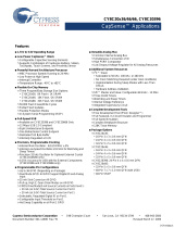
by a library of preverified and precharacterized PSoC Components™, as shown in Figure 1-3. With PSoC Creator, you can:
Drag and drop Components to build your hardware system design in the main design workspace
Codesign your application firmware with the PSoC hardware
Configure Components using configuration tools
Explore the library of 100+ Components
Access Component datasheets
Figure 1-3. PSoC Creator Features
PSoC Creator also enables you to tap into an entire tool ecosystem with integrated compiler chains and production
programmers for PSoC devices.
For more information, visit www.cypress.com/psoccreator.

Introduction
CY8CKIT-044 PSoC® 4 M-Series Pioneer Kit Guide, Doc. No. 001-96598 Rev. *C 11
1.3.1 PSoC Creator Code Examples
PSoC Creator includes a large number of code example projects.
These projects are accessible from the PSoC Creator Start
Page, as shown in Figure 1-4.
Example projects can speed up your design process by starting
you off with a complete design, instead of a blank page. The
example projects also show how to use PSoC Creator
Components for various applications. Code examples and
documentation are included, as shown in Figure 1-5.
In the Find Example Project dialog shown in Figure 1-5, you
have several options:
Filter for examples based on device family or keyword.
Select from the list of examples offered based on the Filter
Options.
View the project documentation for the selection (on the
Documentation tab).
View the code for the selection. You can also copy and
paste code from this window to your project, which can help
speed up code development.
Figure 1-4. Code Examples in PSoC Creator
Create new workspace for the example project. This can speed up your design process by starting you off with a
complete, basic design. You can then adapt that design to your application.
Figure 1-5. Code Example Projects with Sample Code

Introduction
CY8CKIT-044 PSoC® 4 M-Series Pioneer Kit Guide, Doc. No. 001-96598 Rev. *C 12
1.3.2 Kit Example Projects
You can access the installed kit example projects from the PSoC Creator Start Page. To access these example projects,
expand the Kits under the section Examples and Kits; then, expand the specific kit to see the example projects. Refer to
the Using the Kit Example Projects section for a detailed explanation on how to access the kit example projects.
1.3.3 PSoC Creator Help
Launch PSoC Creator and navigate to the following items:
Quick Start Guide: Choose Help > Documentation > Quick Start Guide. This guide gives you the basics for
developing PSoC Creator projects.
Simple Component example projects: Choose File > Open > Example Projects. These example projects
demonstrate how to configure and use PSoC Creator Components. To access example projects related to a specific
Component, place the Component on the TopDesign schematic and right-click on the Component. Select the Find
Example Project option in the context menu that appears.
Starter Designs: Choose File > New > Project and select PSoC 4100M / PSoC 4200M Starter Design. These starter
designs demonstrate the unique features of PSoC 4200M.
System Reference Guide: Choose Help > System Reference > System Reference Guide. This guide lists and
describes the system functions provided by PSoC Creator.
Component Datasheets: Right-click a Component and select Open Datasheet. Visit the PSoC 4 Component
Datasheets page for a list of all PSoC 4 Component datasheets.
Document Manager: PSoC Creator provides a document manager to help you easily find and access the document
resources. To open the document manager, choose the menu item Help > Document Manager.
1.4 Getting Started
This guide will help you be acquainted with the CY8CKIT-044 PSoC 4 M-Series Pioneer Kit:
The Installation chapter describes the installation of the kit software. This includes the PSoC Creator IDE to develop
and debug the applications, and PSoC Programmer to program the .hex files on to the device.
The Kit Operation chapter describes the major features of the PSoC 4 M-Series Pioneer Kit and functionalities such as
programming, debugging, and the USB-UART and USB-I2C bridges.
The Example Projects chapter describes multiple PSoC 4200M code examples that will help you understand how to
create your own PSoC 4 projects.
The Appendix provides the method to use the Micrium µC/Probe, detailed hardware description, method to use the
onboard F-RAM, kit schematics, and the bill of materials (BOM).
1.5 Additional Learning Resources
Cypress provides a wealth of data at www.cypress.com to help you to select the right PSoC device for your design, and to
help you to quickly and effectively integrate the device into your design. For a comprehensive list of resources, see
KBA86521, How to Design with PSoC 3, PSoC 4, and PSoC 5LP. The following is an abbreviated list for PSoC 4:
Overview: PSoC Portfolio and PSoC Roadmap.
Product Selectors: PSoC 4 Product Selector. In addition, PSoC Creator includes a device selection tool.
Datasheets: Describe and provide electrical specifications for the PSoC 4000, PSoC 4100, PSoC 4200, PSoC 4100M,
and PSoC 4200M device families.
CapSense Design Guide: Learn how to design capacitive touch-sensing applications with the PSoC 4 family of
devices.
Application Notes and Code Examples: Cover a broad range of topics, from basic to advanced. Many of the
application notes include code examples. Visit the PSoC 3/4/5 Code Examples web page for a list of all available PSoC
Creator code examples. To access code examples from within PSoC Creator – see PSoC Creator Code Examples.
Technical Reference Manuals (TRM): Provide detailed descriptions of the architecture and registers in each PSoC 4
device family.

Introduction
CY8CKIT-044 PSoC® 4 M-Series Pioneer Kit Guide, Doc. No. 001-96598 Rev. *C 13
Development Kits:
CY8CKIT-042 and CY8CKIT-040 are easy-to-use and inexpensive development platforms. These kits include
connectors for Arduino compatible Shields and Digilent Pmod Peripheral Modules.
CY8CKIT-049 is a very low-cost prototyping platform for sampling PSoC 4 devices.
CY8CKIT-001 is a common development platform for all PSoC family devices.
MiniProg3 device provides an interface for flash programming and debug.
Knowledge Base Articles (KBA): Provide design and application tips from experts on using the device. For instance,
KBA93541 explains how to use CY8CKIT-049 to program another PSoC 4.
PSoC Creator Training: Visit www.cypress.com/go/creatorstart/creatortraining for a comprehensive list of video
trainings on PSoC Creator.
Learning from Peers: Visit www.cypress.com/forums to meet enthusiastic PSoC developers discussing the next
generation embedded systems on Cypress Developer Community Forums.
1.6 Technical Support
For assistance, visit Cypress Support or contact customer support at +1(800) 541-4736 Ext. 2 (in the USA) or +1 (408) 943-
2600 Ext. 2 (International).
1.7 Document Conventions
Table 1-1. Document Conventions for Guides
Convention
Usage
Courier New
Displays file locations, user-entered text, and source code:
C:\ ...cd\icc\
Italics
Displays file names and reference documentation:
Read about the sourcefile.hex file in the PSoC Creator User Guide.
[Bracketed, Bold]
Displays keyboard commands in procedures:
[Enter] or [Ctrl] [C]
File > Open
Represents menu paths:
File > Open > New Project
Bold
Displays commands, menu paths, and icon names in procedures:
Click the File icon and then click Open.
Times New Roman
Displays an equation:
2 + 2 = 4
Text in gray boxes
Describes Cautions or unique functionality of the product.

Installation
CY8CKIT-044 PSoC® 4 M-Series Pioneer Kit Guide, Doc. No. 001-96598 Rev. *C 14
1.8 Acronyms
Table 1-2. Acronyms Used in this Document
Acronym
Description
ADC
Analog-to-Digital Converter
ESD
Electrostatic Discharge
F-RAM
Ferroelectric Random Access Memory
GPIO
General Purpose Input/Output
I2C
Inter-Integrated Circuit
IDE
Integrated Development Environment
LDO
Low Drop Out (voltage regulator)
LED
Light-Emitting Diode
LSB
Least Significant Byte
MSB
Most Significant Byte
PSoC
Programmable Systems-on-Chip
PWM
Pulse Width Modulation
RGB
Red Green Blue
SAR
Successive Approximation Register
SPI
Serial Peripheral Interface
SWD
Serial Wire Debug
UART
Universal Asynchronous Receiver
Transmitter
USB
Universal Serial Bus

CY8CKIT-044 PSoC® 4 M-Series Pioneer Kit Guide, Doc. No. 001-96598 Rev. *C 15
2. Installation
This chapter describes the steps to install the software tools and packages on a PC for using the CY8CKIT-044 PSoC 4 M-
Series Pioneer Kit. This includes the IDE on which the projects will be built and used for programming.
2.1 Before You Begin
To install Cypress software, you will require administrator privileges. However, they are not required to run software that is
already installed. Before you install the kit software, close any other Cypress software that is currently running.
2.2 Install Software
Follow these steps to install the CY8CKIT-044 PSoC 4 M-Series Pioneer Kit software:
1. Download the PSoC 4 M-Series Pioneer Kit software from www.cypress.com/CY8CKIT-044. The kit software is
available in three different formats for download.
a. CY8CKIT-044 Kit Complete Setup: This installation package contains the files related to the kit. However, it
does not include the Windows Installer or Microsoft .NET framework packages. If these packages are not on
your computer, the installer directs you to download and install them from the Internet.
b. CY8CKIT-044 Kit Only: This executable file installs only the kit contents, which include kit code examples,
hardware files, and user documents. This package can be used if all the software prerequisites (listed in step
5) are installed on your PC.
c. CY8CKIT-044 DVD ISO: This file is a complete package, stored in a DVD-ROM image format, which you can
use to create a DVD or extract using an ISO extraction program such as WinZip® or WinRAR. The file can
also be mounted like a virtual CD/DVD using virtual drive programs such as Virtual CloneDrive and MagicISO.
This file includes all the required software, utilities, drivers, hardware files, and user documents.
2. If you have downloaded the ISO file, mount it in a virtual drive. Extract the ISO contents if you do not have a virtual
drive to mount. Double-click cyautorun.exe in the root directory of the extracted content or the mounted ISO if “Autorun
from CD/DVD” is not enabled on the PC. The installation window will appear automatically.
Note: If you are using the “Kit Complete Setup” or “Kit Only” file, then go to step 4 for installation.
3. Click Install CY8CKIT-044 to start the kit installation, as shown in Figure 2-1.

Installation
CY8CKIT-044 PSoC® 4 M-Series Pioneer Kit Guide, Doc. No. 001-96598 Rev. *C 16
Figure 2-1. Kit Installer Screen
4. Select the folder in which you want to install the CY8CKIT-044 kit-related files. Choose the directory and click Next.
5. When you click Next, the CY8CKIT-044 installer automatically installs the required software, if it is not present on your
computer. Following is the required software:
a. PSoC Creator 3.2 or later: This software is available separately from www.cypress.com/psoccreator.
b. PSoC Programmer 3.23 or later: This is installed as part of PSoC Creator installation or is available separately
from www.cypress.com/programmer.
6. Choose the Typical/Custom/Complete installation type in the Product Installation Overview window, as shown in
Figure 2-2. Click Next after you select the installation type.

Installation
CY8CKIT-044 PSoC® 4 M-Series Pioneer Kit Guide, Doc. No. 001-96598 Rev. *C 17
Figure 2-2. Product Installation Overview
7. Read the License agreement and select I accept the terms in the license agreement to continue with installation.
Click Next.
8. When the installation begins, a list of packages appears on the installation page. A green check mark appears next to
each package after successful installation.
9. Enter your contact information or select the check box Continue Without Contact Information. Click Finish to
complete the CY8CKIT-044 kit software installation.
10. After the installation is complete, the kit contents are available at the following location:
<Install_Directory>\CY8CKIT-044 PSoC 4 M-Series Pioneer Kit
Default location:
Windows 7 (64-bit): C:\Program Files (x86)\Cypress\CY8CKIT-044 PSoC 4 M-Series Pioneer Kit
Windows 7 (32-bit): C:\Program Files\Cypress\CY8CKIT-044 PSoC 4 M-Series Pioneer Kit
Note: For Windows 7/8/8.1 users, the installed files and the folder are read only. To use the installed example projects,
follow the steps outlined in the Example Projects chapter.
2.3 Uninstall Software
The software can be uninstalled using one of the following methods:
Go to Start > All Programs > Cypress > Cypress Update Manager and select the Uninstall button that corresponds
to the kit software.
Go to Start > Control Panel > Programs and Features for Windows 7 or Add/Remove Programs for Windows XP;
select the Uninstall/Change button.

CY8CKIT-044 PSoC® 4 M-Series Pioneer Kit Guide, Doc. No. 001-96598 Rev. *C 18
3. Kit Operation
This chapter introduces you to PSoC 4 M-Series Pioneer Kit features.
3.1 Theory of Operation
The PSoC 4 M-Series Pioneer Kit is built around the PSoC 4200M device. Figure 3-1 shows the block diagram of the
PSoC 4200M device. Refer to the PSoC 4200M datasheet for details on device features.
Figure 3-1. PSoC 4200M Block Diagram

Kit Operation
CY8CKIT-044 PSoC® 4 M-Series Pioneer Kit Guide, Doc. No. 001-96598 Rev. *C 19
Figure 3-2 shows the block diagram for the PSoC 4 M-Series Pioneer Kit.
Figure 3-2. Block Diagram of PSoC 4 M-Series Pioneer Kit
PSoC 4200M Arduino Compatible Input/Output Headers
USB
Mini-B
KitProg I/O
Header
PSoC 4200M Arduino Compatible Input/Output Headers
KitProg PSoC 4200M
Rapsberry Pi Compatible Header
10-pin
Debug
10-pin
Debug
PWM
Temp
Sensor
Ambient
Light
Sensor
F-RAM
3-Axis
Accelerometer
Status LED
Reset Button RGB LED Push Button
Level
Translator
Reset
SWD
USB-I2C
USB-UART
Proximity
Proximity
Gesture Pad
Digilent Pmod Compatible Header
32kHz
Crystal
Figure 3-3. PSoC 4 M-Series Pioneer Kit Board Diagram

Appendix
CY8CKIT-044 PSoC® 4 M-Series Pioneer Kit Guide, Doc. No. 001-96598 Rev. *C 20
This kit has the following peripherals:
1. Power and Status LED: The amber power LED is turned on when the kit is connected to a power source. The green
status LED indicates the status of the KitProg.
2. USB Mini-B connector: The USB cable provided along with the PSoC 4 M-Series Pioneer Kit connects between this
connector and the PC.
3. Power Supply: The kit can operate at two voltage levels, 3.3 V and 5 V. The power selection jumper J9 is used to select
between the two voltage levels. The kit has an onboard 3.3-V Low Drop Out (LDO) regulator that converts the 5-V input
to 3.3 V.
4. KitProg: The KitProg is a multi-functional system, which includes a programmer, debugger, USB-I2C bridge, and a
USB-UART bridge. Refer to the KitProg User Guide in the installation folder <Install_Directory>\CY8CKIT-044
PSoC 4 M-Series Pioneer Kit\<version>\Documentation\KitProg_User_Guide.pdf for more details
on the KitProg.
5. KitProg (PSoC 5LP) I/O Header: This header brings out a few Input/Output lines of the onboard PSoC 5LP device. This
includes the KitProg USB-I2C bridge lines and USB-UART bridge lines. The additional PSoC 5LP pins are direct
connections to the internal programmable analog logic of PSoC 5LP. You can use these pins as General-purpose
input/output (GPIO) also. For more details on the KitProg functionality, refer to the KitProg User Guide.
6. PSoC 4200M: This kit is designed to highlight the features of PSoC 4200M.
7. 10-pin programming header for PSoC 4200M: This header allows you to program/debug the PSoC 4200M using an
external programmer such as MiniProg3. PSoC 4 M-Series Pioneer Kit also has through-hole test points to allow you to
program and debug external PSoC 4 and PSoC 5LP devices using the KitProg. You must remove the zero-ohm
resistors R51, R53, and R55 to disconnect the connection between KitProg and the onboard PSoC 4200M device
before programming an external PSoC.
8. Digilent Pmod Peripheral Module compatible header: This header allows you to connect to the PSoC 4200 device to
Pmod Peripheral Modules though I2C and SPI interfaces.
9. Reset Button: This button is used to reset the PSoC 4200M device.
10. Arduino Uno Shield compatible power header: This header powers third-party party Arduino Shields. This header also
has a provision to power the PSoC 4 M-Series Pioneer Kit though the VIN input on the header.
11. RGB LED: The onboard RGB LED can be controlled from the PSoC 4200M device.
12. User Button: This button can be used to provide input to the PSoC 4200M. Note that the switch connects the PSoC
4200M pin to ground when pressed, so you need to configure the PSoC 4200M pin as resistive pull-up for detecting the
switch press.
13. Arduino Uno Shield compatible I/O headers: The PSoC 4 M-Series Pioneer Kit is compatible and operates flawlessly
with third-party Arduino Shields.
14. Raspberry Pi compatible header: A header which is compatible with Raspberry Pi Model B is included on the kit for
enabling advanced embedded systems. A Raspberry Pi can communicate to the PSoC 4200M device using I2C, SPI,
or UART communication protocols. One of the applications of this header is to enable the PSoC 4200M to act as an
analog input processor for Raspberry Pi. The PSoC 4200M, with its CapSense capability, can also enable user
interface functions such as gesture and proximity detection.
15. 3-Axis Accelerometer: This kit features a 3-Axis digital accelerometer device from Kionix®
(KXTJ2-1009). The accelerometer is interfaced to the PSoC 4200M using the I2C protocol.
16. CapSense Proximity Headers: These headers are located on both sides of the CapSense Gesture Pad. They can be
used as individual proximity sensors or can be used together to detect CapSense proximity gestures. The example
project included with this kit demonstrates the detection of wave up and wave down proximity gestures. Remember to
connect wires into the proximity headers before using the proximity functionality. Note that if these inputs are not used
for proximity sensing, then the connectors and the associated I/Os are available for general-purpose use.
17. Current Measurement Jumper: This jumper can be used to measure the current consumed by the PSoC 4200M device
by connecting an ammeter between the pins 3 and 4 of the jumper. Remember to connect the jumper between pin 3
and pin 4 if the current measurement functionality is not used.
18. CapSense Gesture Pad: The CapSense Gesture Pad is a five-element CapSense peripheral specifically intended for
touch gesture recognition. This peripheral can be used to detect swipe left, swipe right, swipe up, swipe down,
clockwise swipe, and counter-clockwise swipe gestures.
Note: The Gesture Pad can also be used as five individual capacitive touch buttons. The Gesture Pad is not intended
to be used as a radial slider.
/