Page is loading ...


Copyrights
CY8CKIT-062S2-43012 PSoC 62S2 Wi-Fi BT Pioneer Kit Guide, Doc. # 002-28109 Rev. *E 2
Copyrights
© Cypress Semiconductor Corporation, 2019–2020. This document is the property of Cypress Semiconductor Corporation
and its subsidiaries (“Cypress”). This document, including any software or firmware included or referenced in this document
(“Software”), is owned by Cypress under the intellectual property laws and treaties of the United States and other countries
worldwide. Cypress reserves all rights under such laws and treaties and does not, except as specifically stated in this
paragraph, grant any license under its patents, copyrights, trademarks, or other intellectual property rights. If the Software is
not accompanied by a license agreement and you do not otherwise have a written agreement with Cypress governing the use
of the Software, then Cypress hereby grants you a personal, non-exclusive, nontransferable license (without the right to
sublicense) (1) under its copyright rights in the Software (a) for Software provided in source code form, to modify and
reproduce the Software solely for use with Cypress hardware products, only internally within your organization, and (b) to
distribute the Software in binary code form externally to end users (either directly or indirectly through resellers and
distributors), solely for use on Cypress hardware product units, and (2) under those claims of Cypress’s patents that are
infringed by the Software (as provided by Cypress, unmodified) to make, use, distribute, and import the Software solely for
use with Cypress hardware products. Any other use, reproduction, modification, translation, or compilation of the Software is
prohibited.
TO THE EXTENT PERMITTED BY APPLICABLE LAW, CYPRESS MAKES NO WARRANTY OF ANY KIND, EXPRESS OR
IMPLIED, WITH REGARD TO THIS DOCUMENT OR ANY SOFTWARE OR ACCOMPANYING HARDWARE, INCLUDING,
BUT NOT LIMITED TO, THE IMPLIED WARRANTIES OF MERCHANTABILITY AND FITNESS FOR A PARTICULAR
PURPOSE. No computing device can be absolutely secure. Therefore, despite security measures implemented in Cypress
hardware or software products, Cypress shall have no liability arising out of any security breach, such as unauthorized access
to or use of a Cypress product. CYPRESS DOES NOT REPRESENT, WARRANT, OR GUARANTEE THAT CYPRESS
PRODUCTS, OR SYSTEMS CREATED USING CYPRESS PRODUCTS, WILL BE FREE FROM CORRUPTION, ATTACK,
VIRUSES, INTERFERENCE, HACKING, DATA LOSS OR THEFT, OR OTHER SECURITY INTRUSION (collectively,
“Security Breach”). Cypress disclaims any liability relating to any Security Breach, and you shall and hereby do release
Cypress from any claim, damage, or other liability arising from any Security Breach. In addition, the products described in
these materials may contain design defects or errors known as errata which may cause the product to deviate from published
specifications. To the extent permitted by applicable law, Cypress reserves the right to make changes to this document
without further notice. Cypress does not assume any liability arising out of the application or use of any product or circuit
described in this document. Any information provided in this document, including any sample design information or
programming code, is provided only for reference purposes. It is the responsibility of the user of this document to properly
design, program, and test the functionality and safety of any application made of this information and any resulting product.
“High-Risk Device” means any device or system whose failure could cause personal injury, death, or property damage.
Examples of High-Risk Devices are weapons, nuclear installations, surgical implants, and other medical devices. “Critical
Component” means any component of a High-Risk Device whose failure to perform can be reasonably expected to cause,
directly or indirectly, the failure of the High-Risk Device, or to affect its safety or effectiveness. Cypress is not liable, in whole
or in part, and you shall and hereby do release Cypress from any claim, damage, or other liability arising from any use of a
Cypress product as a Critical Component in a High-Risk Device. You shall indemnify and hold Cypress, its directors, officers,
employees, agents, affiliates, distributors, and assigns harmle
ss from and against all claims, costs, damages, and expenses,
arising out of any claim, including claims for product liability, personal injury or death, or property damage arising from any
use of a Cypress product as a Critical Component in a High-Risk Device. Cypress products are not intended or authorized for
use as a Critical Component in any High-Risk Device except to the limited extent that (i) Cypress’s published data sheet for
the product explicitly states Cypress has qualified the product for use in a specific High-Risk Device, or (ii) Cypress has given
you advance written authorization to use the product as a Critical Component in the specific High-Risk Device and you have
signed a separate indemnification agreement.
Cypress, the Cypress logo, Spansion, the Spansion logo, and combinations thereof, WICED, PSoC, CapSense, EZ-USB, F-
RAM, and Traveo are trademarks or registered trademarks of Cypress in the United States and other countries. For a more
complete list of Cypress trademarks, visit cypress.com. Other names and brands may be claimed as property of their
respective owners.

CY8CKIT-062S2-43012 PSoC 62S2 Wi-Fi BT Pioneer Kit Guide, Doc. # 002-28109 Rev. *E 3
Contents
Safety and Regulatory Compliance Information 5
1. Introduction 8
1.1 Kit Contents .................................................................................................................9
1.2 Getting Started...........................................................................................................10
1.3 Board Details .............................................................................................................10
1.4 Additional Learning Resources..................................................................................16
1.5 Technical Support......................................................................................................16
1.6 Documentation Conventions......................................................................................16
1.7 Acronyms...................................................................................................................17
2. Kit Operation 19
2.1 Theory of Operation...................................................................................................19
2.2 KitProg3: On-Board Programmer/Debugger..............................................................24
2.2.1 Programming and Debugging using ModusToolbox ......................................24
2.2.2 USB-UART Bridge..........................................................................................28
2.2.3 USB-I2C Bridge..............................................................................................29
3. Hardware 30
3.1 Schematics ................................................................................................................30
3.2 Hardware Functional Description...............................................................................30
3.2.1 CY8CMOD-062S2-43012 (MOD1).................................................................30
3.2.2 PSoC 5LP-based KitProg3 (U2).....................................................................35
3.2.3 Serial Interconnection between PSoC 5LP and PSoC 6 MCU ......................36
3.2.4 Serial Interconnection Between PSoC 5LP and CYW43012 .........................37
3.2.5 Power Supply System ....................................................................................37
3.2.6 I/O Headers....................................................................................................40
3.2.7 CapSense Circuit ...........................................................................................41
3.2.8 LEDs ..............................................................................................................42
3.2.9 Push Buttons..................................................................................................43
3.2.10 Cypress Quad SPI NOR Flash.......................................................................43
3.2.11 Cypress Quad SPI F-RAM .............................................................................44
3.2.12 microSD card section .....................................................................................44
3.2.13 PSoC 6 USB Section .....................................................................................45
3.2.14 Potentiometer Section....................................................................................45
3.3 PSoC 62S2 Wi-Fi BT Pioneer Kit Rework .................................................................46
3.3.1 CapSense Shield ...........................................................................................46
3.3.2 ETM Trace Header.........................................................................................46
3.3.3 microSD Card Detect Multiplexing .................................................................46
3.3.4 microSD Card SPI Multiplexing......................................................................47
3.3.5 U.FL (UMCC) Connector for External Antenna ..............................................47
3.3.6 U.FL (UMCC) Connector for Antenna Diversity..............................................47

CY8CKIT-062S2-43012 PSoC 62S2 Wi-Fi BT Pioneer Kit Guide, Doc. # 002-28109 Rev. *E 4
Contents
3.4 Bill of Materials ..........................................................................................................48
3.5 Frequently Asked Questions......................................................................................48
Revision History 50

CY8CKIT-062S2-43012 PSoC 62S2 Wi-Fi BT Pioneer Kit Guide, Doc. # 002-28109 Rev. *E 5
Safety and Regulatory Compliance
Information
The CY8CKIT-062S2-43012 PSoC
®
62S2 Wi-Fi BT Pioneer Kit is intended for development
purposes only. Users are advised to test and evaluate this kit in an RF development environment.
This kit is not a finished product and when assembled may not be resold or otherwise marketed
unless all required authorizations are first obtained. Contact support@cypress.com for details.
The CY8CKIT-062S2-43012, as shipped from the factory, has been verified to meet with the
requirements of CE as a Class A product.
PSoC 62S2 Wi-Fi BT Pioneer Boards contain electrostatic discharge
(ESD)- sensitive devices. Electrostatic charges readily accumulate on
the human body and any equipment, which can cause a discharge
without detection. Permanent damage may occur on devices
subjected to high-energy discharges. Proper ESD precautions are
recommended to avoid performance degradation or loss of
functionality. Store unused PSoC 62S2 Wi-Fi BT Pioneer Boards in the
protective shipping package.
End-of-Life/Product Recycling
The end-of-life cycle for this kit is five years from the date of
manufacture mentioned on the back of the box. Contact your nearest
recycler to discard the kit.

CY8CKIT-062S2-43012 PSoC 62S2 Wi-Fi BT Pioneer Kit Guide, Doc. # 002-28109 Rev. *E 6
General Safety Instructions
ESD Protection
ESD can damage boards and associated components. Cypress recommends that you perform
procedures only at an ESD workstation. If an ESD workstation is unavailable, use appropriate ESD
protection by wearing an anti-static wrist strap attached to a grounded metal object.
Handling Boards
CY8CKIT-062S2-43012 PSoC 62S2 Wi-Fi BT Pioneer Kit is sensitive to ESD. Hold the board only by
its edges. After removing the board from its box, place it on a grounded, static-free surface. Use a
conductive foam pad, if available. Do not slide the board over any surface.
Regulatory Compliance Information
The CY8CKIT-062S2-43012 PSoC 62S2 Wi-Fi BT Pioneer Kit contains devices that transmit and
receive radio signals in accordance with the spectrum regulations for the 2.4-GHz and 5-GHz
unlicensed frequency range.
Cypress Semiconductor Corporation has obtained regulatory approvals for this kit to be used in
specific countries. These countries include the United States (FCC Part 15), Canada (IC RSS210),
and Japan (JRF/TELEC). Additional regional regulatory agency approval may be required to operate
these throughout the world.
This kit, as shipped from the factory, has been tested and found to comply with the limits and
requirements for the following compliances:
■ As a Class B digital device, pursuant to part 15 of the FCC Rules.
■ As a Class B digital apparatus, compliant with Canadian ICES-003.
CAUTION:
Only the antenna(s) that were certified with the module may be used.
Other antennas may be used only if they are of the same type and have
the same or lower gain.
The manufacturer is not responsible for any radio or television
interference caused by unauthorized modifications to this equipment.
Such modifications could void the user's authority to operate the
equipment.

CY8CKIT-062S2-43012 PSoC 62S2 Wi-Fi BT Pioneer Kit Guide, Doc. # 002-28109 Rev. *E 7
Regulatory Statements and Product Labeling
United States (FCC)
The CY8CKIT-062S2-43012 contains Type1LV modular transmitter that complies with Part 15 of the
Federal Communications Commission (FCC) Rules.
The FCC ID for this device is VPYLBEE59B1LV.
Operation is subject to the following two conditions:
■ This device may not cause harmful interference
■ This device must accept any interference received, including interference that may cause unde-
sired operation.
CAUTION: Changes or modifications not expressly approved by the party responsible for
compliance could void the user’s authority to operate the equipment. The antennas for this
transmitter must be installed to provide a separation distance of 20 cm from all persons and must not
be co-located or operating in conjunction with any other antenna or transmitter.
Canada (IC)
This device complies with the Industry Canada license-exempt RSS standard(s). Operation is sub-
ject to the following two conditions:
■ This device may not cause interference.
■ This device must accept any interference, including interference that may cause undesired oper-
ation of the device.
This equipment complies with radio frequency exposure limits set forth by Industry Canada for an
uncontrolled environment. This equipment should be installed and operated with minimum distance
20 cm between the device and the user or bystanders.
CAUTION: Any changes or modifications not expressly approved by the party responsible for
compliance could void the user’s authority to operate the equipment.
Contains IC: 772C-LBEE59B1LV
Le présent appareil est conforme aux CNR d'Industrie Canada applicables aux appareils radio
exempts de licence. L'exploitation est autorisée aux deux conditions suivantes: (1) l'appareil ne doit
pas produire de brouillage, et (2) l'utilisateur de l'appareil doit accepter tout brouillage radioélectrique
subi, même si le brouillage est susceptible d'en compromettre le fonctionnement.
Cet équipement est conforme aux limites d'exposition aux radiofréquences définies par Industrie
Canada pour un environnement non contrôlé. Cet équipement doit être installé et utilisé avec un
minimum de 20cm de distance entre le dispositif et l'utilisateur ou des tiers.
Contains IC: 772C-LBEE59B1LV
Japan (TELEC)
Manufactured by Murata Manufacturing
001-P01338
R

CY8CKIT-062S2-43012 PSoC 62S2 Wi-Fi BT Pioneer Kit Guide, Doc. # 002-28109 Rev. *E 8
1. Introduction
Thank you for your interest in the CY8CKIT-062S2-43012 PSoC 62S2 Wi-Fi BT Pioneer Kit. The
PSoC 62S2 Wi-Fi BT Pioneer Kit enables you to evaluate and develop your applications using the
PSoC 62 Series MCU (hereafter called “PSoC 6 MCU”) and CYW43012 WICED Wi-Fi/BT combo
device.
PSoC 6 MCU is Cypress’ latest, ultra-low-power PSoC specifically designed for wearables and IoT
products. PSoC 6 MCU is a true programmable embedded system-on-chip, integrating a 150-MHz
Arm
®
Cortex
®
-M4 as the primary application processor, a 100-MHz Arm Cortex-M0+ that supports
low-power operations, up to 2 MB Flash and 1 MB SRAM, Secure Digital Host Controller (SDHC)
supporting SD/SDIO/eMMC interfaces, CapSense
®
touch-sensing, and programmable analog and
digital peripherals that allow higher flexibility, in-field tuning of the design, and faster time-to-market.
The PSoC 6 BLE Pioneer Board offers compatibility with Arduino™ shields. The board features a
PSoC 6 MCU, and a CYW43012 Wi-Fi/Bluetooth combo module. Cypress CYW43012 is a 28-nm,
ultra-low-power device that supports single-stream, dual-band IEEE 802.11n-compliant Wi-Fi MAC/
baseband/radio and Bluetooth 5.0 BR/EDR/LE. The WLAN section supports SDIO interface to the
host MCU (PSoC 6 MCU), and the Bluetooth section supports high-speed 4-wire UART interface to
the host MCU. In addition, the board features an onboard programmer/debugger (KitProg3), a
512-Mbit Quad SPI NOR flash, a 4-Mbit Quad SPI F-RAM, a micro-B connector for USB device
interface, a 5-segment CapSense slider, two CapSense buttons, a microSD card holder, an RGB
LED, two user LEDs, one potentiometer, and two push buttons. The board supports operating
voltages from 1.8 V to 3.3 V for PSoC 6 MCU.
You can use ModusToolbox™ to develop and debug your PSoC 6 MCU projects. ModusToolbox
software is a set of tools that enable you to integrate Cypress devices into your existing development
methodology.
If you are new to PSoC 6 MCU and ModusToolbox IDE, refer to the application note AN221774 -
Getting Started with PSoC 6 MCU to help you familiarize with the PSoC 6 MCU and help you create
your own design using the ModusToolbox IDE.

CY8CKIT-062S2-43012 PSoC 62S2 Wi-Fi BT Pioneer Kit Guide, Doc. # 002-28109 Rev. *E 9
Introduction
1.1 Kit Contents
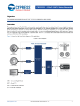
The CY8CKIT-062S2-43012 PSoC 62S2 Wi-Fi BT Pioneer Kit has the following contents, as shown
in Figure 1-1.
■ PSoC 62S2 Wi-Fi BT Pioneer Board
■ USB Type-A to Micro-B cable
■ Four jumper wires (4 inches each)
■ Two jumper wires (5 inches each)
■ Quick Start Guide
Figure 1-1. Kit Contents
Inspect the contents of the kit; if you find any part missing, contact your nearest Cypress sales office
for help: www.cypress.com/support.

CY8CKIT-062S2-43012 PSoC 62S2 Wi-Fi BT Pioneer Kit Guide, Doc. # 002-28109 Rev. *E 10
Introduction
1.2 Getting Started
This guide will help you get acquainted with the PSoC 62S2 Wi-Fi BT Pioneer Kit:
■ The Kit Operation chapter on page 19 describes the major features of the PSoC 62S2 Wi-Fi BT
Pioneer Kit and functionalities such as programming, debugging, and the USB-UART and USB-
I
2
C bridges.
■ The Hardware chapter on page 30 provides a detailed hardware description, methods to use the
onboard NOR flash, kit schematics, and the bill of materials (BOM).
■ Application development using PSoC 62S2 Wi-Fi BT Pioneer Kit is supported in various
development ecosystems such as ModusToolbox and Mbed OS. For the latest software support
for this development kit including the different development ecosystems, refer to the kit webpage.
❐ ModusToolbox software is a free development ecosystem that includes the ModusToolbox
IDE. Using ModusToolbox IDE, you can enable and configure device resources, middleware
libraries, and program and debug the device. You can download the software from the
ModusToolbox home page. See the ModusToolbox User Guide for additional information.
❐ Mbed OS: Visit Cypress’ Mbed OS page on instructions to develop applications on Cypress’
target board on the Mbed OS platform.
■ There are wide range of code examples to evaluate the PSoC 62S2 Wi-Fi BT Pioneer board.
These examples help you familiarize PSoC 6 MCU and create your own design. These examples
are available in various development ecosystems such as ModusToolbox IDE and Mbed OS.
Visit Cypress’ code example page to access examples for the following development
ecosystems:
❐ ModusToolbox based examples
❐ Mbed OS based examples
1.3 Board Details
The PSoC 62S2 Wi-Fi BT Pioneer Board that has the following features:
■ CY8CMOD-062S2-43012 carrier module that contains
❐ PSoC 6 MCU (CY8C624ABZI-S2D44)
❐ Murata 1LV ultra-small 2.4/5.0-GHz WLAN and Bluetooth functionality module based on
CYW43012
■ 512-Mbit external Quad SPI NOR Flash that provides a fast, expandable memory for data and
code
■ 4-Mbit Quad SPI ferroelectric random-access memory (F-RAM)
■ KitProg3 onboard SWD programmer/debugger with USB-UART and USB-I2C bridge functionality
■ CapSense touch-sensing slider (5 elements), two buttons, based on self-capacitance (CSD) and
mutual-capacitance (CSX) sensing
■ A micro-B connector for USB device interface for PSoC 6 MCU
■ 1.8 V and 3.3 V operation of PSoC 6 MCU is supported
■ Two user LEDs, an RGB LED, two user buttons, and a reset button for PSoC 6 MCU
■ A potentiometer
■ One Mode selection button and one Status LED for KitProg3
■ A microSD Card holder

CY8CKIT-062S2-43012 PSoC 62S2 Wi-Fi BT Pioneer Kit Guide, Doc. # 002-28109 Rev. *E 11
Introduction
Figure 1-2 shows the pinout of the Pioneer Board.
Figure 1-2. Pioneer Board Pinout
Table 1-1. Pioneer Board Pinout
Pin
Primary On-board
Function
Secondary On-board
Function
Connection details
PSoC 6 MCU Pins
XRES Hardware Reset – –
P0[2] GPIO on non-Arduino
header IO0 (J22.1)
––
P0[3] GPIO on non-Arduino
header IO1 (J22.2)
––
P0[4] User button with
Hibernate wakeup
capability
GPIO on non-Arduino
header (J21.9)
–
P0[5] RGB green LED
(LED5)
GPIO on non-Arduino
header (J24.3)
–
Arduino Uno R3
LEGEND
PSoC 6 I/Os
WL/BT I/Os
NC
VTRAG/IOREF
XRES/RESET
V 3.3/3.3V
V 5.0/5V
GND/GND
GND/GND
VIN/Vin
P6_0/SCL
P6_1/SDA
VREF/AREF
GND/GND
P12_2/D13
P12_1/D12
P12_0/D11
P12_3/D10
P7_6/D9
P7_5/D8
P5_7/D7
P5_6/D6
P5_5/D5
P5_4/D4
P5_3/D3
P5_2/D2
P5_1/D1
P5_0/D0
P1_4
P0_4
P7_4
NC
NC
NC
NC
NC
NC
NC
NC
P13_5
P13_4
P8_0
P13_6
P1_3
P0_3
P0_2
P10_0/A0
P10_1/A1
P10_2/A2
P10_3/A3
P10_4/A4
P10_5/A5
P10_6
P10_7
P9_0
P9_1
P9_2
P9_3
P9_4
P9_5
P9_6
P9_7
BT_UART_RXD
BT_UART_TXD
BT_UART_CTS
BT_UART_RTS
WL_UART_RX
WL_UART_TX
WL_IO1
WL_IO2
P7_3
P0_5
P1_1
NC
P11_1
P1_5
BT_I2S_CLK
BT_I2S_WS
BT_I2S_DO
BT_I2S_DI
BT_IO2
BT_IO3
BT_IO4
BT_IO5

CY8CKIT-062S2-43012 PSoC 62S2 Wi-Fi BT Pioneer Kit Guide, Doc. # 002-28109 Rev. *E 12
Introduction
P1[0] CapSense RX for
buttons and
CapSense TX for
sliders
GPIO on non-Arduino
header IO7 (J22.8)
Remove R33 to disconnect from CapSense.
Populate R145 to connect to GPIO on non-
Arduino header.
P1[1] RGB red LED (LED5) GPIO on non-Arduino
header (J24.1)
–
P1[2] USB Host Enable – –
P1[3] GPIO on non-Arduino
header J22.3
––
P1[4] User button with
Hibernate wakeup
capability
GPIO on non-Arduino
header (J21.10)
–
P1[5] Orange user LED
(LED8)
GPIO on non-Arduino
header (J24.2)
–
P5[0] UART_RX Arduino D0 (J4.1) Remove R21 to disconnect from KitProg3.
P5[1] UART_TX Arduino D1 (J4.2) Remove R61 to disconnect from KitProg3.
P5[2] UART_RTS Arduino D2 (J4.3) Remove R19 to disconnect from KitProg3.
P5[3] UART_CTS Arduino D3 (J4.4) Remove R18 to disconnect from KitProg3.
P5[4] Arduino D4 (J4.5) – –
P5[5] Arduino D5 (J4.6) – –
P5[6] Arduino D6 (J4.7) – –
P5[7] Arduino D7 (J4.8) – –
P6[0] I2C SCL Arduino (J3.10) Remove R58 to disconnect from KitProg3.
P6[1] I2C SDA Arduino (J3.9) Remove R59 to disconnect from KitProg3.
P6[2] USB VBUS Detect – –
P6[3] USB Interrupt – –
P6[4] PSoC 6 MCU JTAG
TDO/SWD SWO
––
P6[5] PSoC 6 MCU JTAG
TDI
––
P6[6] PSoC 6 MCU JTAG
TMS/SWD SWDIO
––
P6[7] PSoC 6 MCU JTAG
TCK/SWD SWCLK
––
P7[0] ETM Clock – –
P7[1] CapSense CINTA – –
P7[2] CapSense CINTB – –
P7[3] RGB blue LED
(LED5)
GPIO on non-Arduino
header (J24.5)
–
Table 1-1. Pioneer Board Pinout (continued)
Pin
Primary On-board
Function
Secondary On-board
Function
Connection details

CY8CKIT-062S2-43012 PSoC 62S2 Wi-Fi BT Pioneer Kit Guide, Doc. # 002-28109 Rev. *E 13
Introduction
P7[4] GPIO on non-Arduino
header IO15 (J21.8)
CapSense Shield Remove R155 to disconnect from IO15
(J21.8).
Populate R38 to connect to CapSense
Shield.
P7[5] Arduino D8 (J3.1) – –
P7[6] Arduino D9 (J3.2) – –
P7[7] CapSense CMOD – –
P8[0] GPIO on non-Arduino
header (J22.5)
––
P8[1] CapSense Button0
TX
GPIO on non-Arduino
header IO8 (J21.1)
Remove R24 to disconnect from CapSense.
Populate R144 to connect to GPIO on non-
Arduino header.
P8[2] CapSense Button1
TX
GPIO on non-Arduino
header IO9 (J21.2)
Remove R25 to disconnect from CapSense.
Populate R143 to connect to GPIO on non-
Arduino header.
P8[3] CapSense Slider0
RX
GPIO on non-Arduino
header IO10 (J21.3)
Remove R28 to disconnect from CapSense.
Populate R142 to connect to GPIO on non-
Arduino header.
P8[4] CapSense Slider1
RX
GPIO on non-Arduino
header IO11 (J21.4)
Remove R29 to disconnect from CapSense.
Populate R152 to connect to GPIO on non-
Arduino header.
P8[5] CapSense Slider2
RX
GPIO on non-Arduino
header IO12 (J21.5)
Remove R30 to disconnect from CapSense.
Populate R153 to connect to GPIO on non-
Arduino header.
P8[6] CapSense Slider3
RX
GPIO on non-Arduino
header IO13 (J21.6)
Remove R31 to disconnect from CapSense.
Populate R151 to connect to GPIO on non-
Arduino header.
P8[7] CapSense Slider4
RX
GPIO on non-Arduino
header IO14 (J21.7)
Remove R32 to disconnect from CapSense.
Populate R149 to connect to GPIO on non-
Arduino header.
P9[0] Extended Arduino A8
(J2.2)
ETM TRACEDATA[3] Remove R125 to disconnect from J2
header.
Populate R126 to connect to ETM Trace
header.
P9[1] Extended Arduino A9
(J2.4)
ETM TRACEDATA[2] Remove R124 to disconnect from J2
header.
Populate R127 to connect to ETM Trace
header.
P9[2] Extended Arduino
A10 (J2.6)
ETM TRACEDATA[1] Remove R123 to disconnect from J2
header.
Populate R128 to connect to ETM Trace
header.
Table 1-1. Pioneer Board Pinout (continued)
Pin
Primary On-board
Function
Secondary On-board
Function
Connection details

CY8CKIT-062S2-43012 PSoC 62S2 Wi-Fi BT Pioneer Kit Guide, Doc. # 002-28109 Rev. *E 14
Introduction
P9[3] Extended Arduino
A11 (J2.8)
ETM TRACEDATA[0] Remove R117 to disconnect from J2 header.
Populate R129 to connect to ETM Trace
header.
P9[4] Extended Arduino
A12 (J2.10)
––
P9[5] Extended Arduino
A13 (J2.12)
––
P9[6] Extended Arduino
A14 (J2.14)
––
P9[7] Extended Arduino
A15 (J2.16)
––
P10[0] Arduino A0 (J2.1) – –
P10[1] Arduino A1 (J2.3) – –
P10[2] Arduino A2 (J2.5) – –
P10[3] Arduino A3 (J2.7) – –
P10[4] Arduino A4 (J2.9) – –
P10[5] Arduino A5 (J2.11) – –
P10[6] Potentiometer output Extended Arduino A6
(J2.13)
Remove R51 to disconnect from
potentiometer.
P10[7] Extended Arduino A7
(J2.15)
––
P11[0] QSPI F-RAM CS – –
P11[1] Red user LED
(LED9)
GPIO on non-Arduino
header (J24.4)
–
P11[2] QSPI Flash CS – –
P11[3:6] QSPI Flash IO[3:0] – –
P11[7] QSPI Flash CLK – –
P12[0] Arduino header D11
(J3.4)
––
P12[1] Arduino header D12
(J3.5)
––
P12[2] Arduino header D13
(J3.6)
––
P12[3] Arduino header D10
(J3.3)
––
P12[4] microSD card CMD – Remove R168 to disconnect from microSD
card connector.
P12[5] microSD card CLK – Remove R166 to disconnect from microSD
card connector.
P12[6] ECO Crystal XIN – –
P12[7] ECO Crystal XOUT – –
Table 1-1. Pioneer Board Pinout (continued)
Pin
Primary On-board
Function
Secondary On-board
Function
Connection details

CY8CKIT-062S2-43012 PSoC 62S2 Wi-Fi BT Pioneer Kit Guide, Doc. # 002-28109 Rev. *E 15
Introduction
P13[0] microSD card DAT0 microSD card MOSI Remove R164 to disconnect from microSD
port (J20.7).
Populate R169 to connect to microSD
(J20.3).
P13[1] microSD card DAT1 microSD card MISO Remove R163 to disconnect from microSD
port (J20.8).
Populate R165 to connect to microSD
(J20.7).
P13[2] microSD card DAT2 microSD card SPI CLK Remove R162 to disconnect from microSD
port (J20.1)
Populate R167 to connect to microSD
(J20.5)
P13[3] microSD card DAT3 microSD card SPI
SSEL
–
P13[4] GPIO on non-Arduino
header IO5 (J22.6)
––
P13[5] GPIO on non-Arduino
header IO6 (J22.7)
––
P13[6] GPIO on non-Arduino
header IO3 (J22.4)
––
P13[7] microSD card chip
detect
GPIO on non-Arduino
header IO16 (J24.6)
Remove R161 to disconnect from microSD
card detect
Populate R160 to connect to IO16 (J24.6)
CYW43012 Pins
BT_UART_TXD UART interface with
Host MCU (PSoC 6
MCU)
––
BT_UART_RXD UART interface with
Host MCU (PSoC 6
MCU)
––
BT_UART_CTS UART interface with
Host MCU (PSoC 6
MCU)
––
BT_UART_RTS UART interface with
Host MCU (PSoC 6
MCU)
––
BT_I2S_CLK I2S serial clock – –
BT_I2S_WS I2S serial word select – –
BT_I2S_DO I2S serial data out – –
BT_I2S_DI I2S serial data in – –
BT_IO_2 Bluetooth general-
purpose I/Os
––
BT_IO_3 Bluetooth general-
purpose I/Os
––
Table 1-1. Pioneer Board Pinout (continued)
Pin
Primary On-board
Function
Secondary On-board
Function
Connection details

CY8CKIT-062S2-43012 PSoC 62S2 Wi-Fi BT Pioneer Kit Guide, Doc. # 002-28109 Rev. *E 16
Introduction
1.4 Additional Learning Resources
Cypress provides a wealth of data at www.cypress.com/psoc6 to help you to select the right PSoC
device for your design and to help you to quickly and effectively integrate the device into your
design.
1.5 Technical Support
For assistance, visit Cypress Support or contact customer support at +1(800) 541-4736 Ext. 3 (in the
USA) or +1 (408) 943-2600 Ext. 3 (International).
You can also use the following support resources if you need quick assistance:
■ Self-help (Technical Documents).
■ Local Sales Office Locations.
1.6 Documentation Conventions
BT_IO_4 Bluetooth general-
purpose I/Os
––
BT_IO_5 Bluetooth general-
purpose I/Os
––
WL_UART_RX Wi-Fi debug UART
Rx pin
––
WL_UART_TX Wi-Fi debug UART
Tx Pin
––
WL_GPIO_1 Programable GPIO – –
WL_GPIO_2 Programable GPIO – –
Table 1-2. Document Conventions for Guides
Convention Usage
Courier New Displays file locations, user entered text, and source code:
C:\...cd\icc\
Italics Displays file names and reference documentation:
Read about the sourcefile.hex file in the PSoC Creator User Guide.
File > Open Represents menu paths:
File > Open > New Project
Bold Displays commands, menu paths, and icon names in procedures:
Click the File icon and then click Open.
Times New Roman Displays an equation:
2 + 2 = 4
Text in gray boxes Describes cautions or unique functionality of the product.
Table 1-1. Pioneer Board Pinout (continued)
Pin
Primary On-board
Function
Secondary On-board
Function
Connection details

CY8CKIT-062S2-43012 PSoC 62S2 Wi-Fi BT Pioneer Kit Guide, Doc. # 002-28109 Rev. *E 17
Introduction
1.7 Acronyms
Table 1-3. Acronyms Used in this Document
Acronym Definition
ADC Analog-to-Digital Converter
BLE Bluetooth Low Energy
BOM Bill of Materials
BT Bluetooth
CINT Integration Capacitor
CMOD Modulator Capacitor
CPU Central Processing Unit
CSD CapSense Sigma Delta
CSX CapSense Crosspoint
DC Direct Current
Del-Sig Delta-Sigma
DMA Direct Memory Access
ECO External Crystal Oscillator
ESD Electrostatic Discharge
GPIO General-Purpose Input/Output
HID Human Interface Device
I2C Inter-Integrated Circuit
I2S Inter-IC Sound
IC Integrated Circuit
IDE Integrated Development Environment
IoT Internet of Things
LED Light-emitting Diode
LPO Low Power Oscillator
PC Personal Computer
PDM Pulse Density Modulation
PSoC Programmable System-on-Chip
PWM Pulse Width Modulation
QSPI Quad Serial Peripheral Interface
SAR Successive Approximation Register
SDHC Secure Digital Host Controller
SDIO Secure Digital Input Output
SMIF Serial Memory Interface
SPI Serial Peripheral Interface
SRAM Serial Random Access Memory

CY8CKIT-062S2-43012 PSoC 62S2 Wi-Fi BT Pioneer Kit Guide, Doc. # 002-28109 Rev. *E 18
Introduction
SWD Serial Wire Debug
UART Universal Asynchronous Receiver Transmitter
USB Universal Serial Bus
WCO Watch Crystal Oscillator
Table 1-3. Acronyms Used in this Document (continued)
Acronym Definition

CY8CKIT-062S2-43012 PSoC 62S2 Wi-Fi BT Pioneer Kit Guide, Doc. # 002-28109 Rev. *E 19
2. Kit Operation
This chapter introduces you to various features of the PSoC 62S2 Wi-Fi BT Pioneer Board, including
the theory of operation and the onboard KitProg3 programming and debugging functionality,
USB-UART and USB-I2C bridges.
2.1 Theory of Operation
The PSoC 62S2 Wi-Fi BT Pioneer Board is built around a PSoC 6 MCU. Figure 2-1 shows the block
diagram of the PSoC 6 MCU device used on the board. For details of device features, see the device
datasheet.
Figure 2-2 shows the block diagram of the CYW9-BASE-01 Pioneer Board (modified for CY8CKIT-
062S2-43012).
Figure 2-1. PSoC 6 MCU Block Diagram
WCO
RTC
BREG
Backup
Backup Control
IO Subsystem
Peripheral Interconnect (MMIO,PPU)
IOSS GPIO
PCLK
8x SCB
I2C,SPI,UART
98x GPIO Enh, 6x GPIO OVT
CPU Subsystem
System Interconnect (Multi Layer AHB, IPC, MPU/SMPU)
CRYPTO
AES,SHA,CRC,
TRNG,RSA,ECC
Initiator/MMIO
High Speed I/O Matrix, Smart I/O, Boundary Scan
1x SCB
I2C,SPI
PSoC 62
CY8C62X8 ,
CY8C62XA
Digital DFT
Test
Analog DFT
System Resources
Power
Reset
Sleep Control
PWRSYS-LP/ULP
REF
POR
Reset Control
TestMode Entry
XRES
LVD
BOD
DeepSleep
Hibernate
Active/Sleep
LowePowerActive/Sleep
Power Modes
Backup
OVP
Clock
Clock Control
IMO
WDT
2xPLL
ECO
ILO
FLL
32x TCPWM
TIMER,CTR,QD, PWM
SWJ/MTB/CTI
MUL, NVIC, MPU
Cortex M0+
100 MHz (1.1V)
25 MHz (0.9V)
2x Smart IO
EFUSE
1024 bit
Prog.
Analog
SAR
ADC
(12-bit)
x1
SARMUX
Prog.
Analog
SWJ/ETM/ITM/CTI
Cortex M4
150 MHz (1.1V)
50 MHz (0.9V)
FPU, NVIC, MPU
SONOS
FLASH
2048+32 KB
FLASH Controller
8 KB $ 8 KB $
SRAM0
512 KB
SRAM Controller
ROM
64 KB
ROM Controller
SMIF
Serial Memory Interface (QSPI)
2x SDHC
SD/SDIO/eMMC
2x LPCOMP
Low Power Comparator
CSD
CapSense
Energy Profiler
Buck
4x SCB
I2C, UART
SRAM1
256 KB
SRAM Controller
2x I2S
PDM/PCM
Audio
Subsystem
DMA
MMIO
USB-FS
Host + Device
FS/LS
PHY
SRAM2
256 KB
SRAM Controller
DMA
4 Channel
DW1
29 Channel
DW0
29 Channel
LCD

CY8CKIT-062S2-43012 PSoC 62S2 Wi-Fi BT Pioneer Kit Guide, Doc. # 002-28109 Rev. *E 20
Kit Operation
Figure 2-2. Block Diagram of Pioneer Board
The PSoC 62S2 Wi-Fi BT Pioneer Kit comes with the PSoC 62S2 Wi-Fi BT Pioneer Board.
Figure 2-3 and Figure 2-4 show the markup of the Pioneer Board.
Figure 2-3. PSoC 62S2 Wi-Fi BT Pioneer Board - Top View
USB
(Micro‐B)
KitProg3
(PSoC5LP)
KitProg3Mode
Switch&LED
Carrier
Module
10‐pinSWD/
JTAGheader
20‐PinETM
header
Reset
Button
microSDCard
Slot
PSoC6MCUI/
OHeaders
(Arduino)
UserLEDs
(RGB,Red,
Orange)
I2C/UART_RX/UART_TX
SWD
SWD
JTAG
TRACE
QSPINOR
Flash
SWD
JTAG
P5LP_VDD
VTARG
VDDIO_0
2xUser
buttons
2xCapSenseButtons,
1x5‐segment
CapSenseSlider
1.8~3.3V
VTARG_REF
UART_RTS
Level
Translator
USBHost&Device
1.8~3.3V
VTARG_REF
VTARG
Monitoring
CYW9‐BASE‐01ArchitectureBlockDiagram
UART_CTS
Level
Translator
BT_UARTTX,RX,CTS,RTS
WL_UARTTX,RX,KP_GPIO_0
WL_VDDIO
P5LP_VDD
VDDIO_0
I2CEEPROM
QSPIF‐RAM
VDDIO_0
CypressDevice
NoLoad
LoadedDevice
Potentiometer
P5LP_VDD
VTARG
VDDA
3.3V,VTARG
KP_VBUS
PSoC6MCUI/
OHeaders
(NonArduino)
VDDD
VBACKUP
1
2
3
4
5
6
7
8
9 10 9 11 12 13 14 15 16 17
20
19
18
22
21
23
24
25
26
27
28
29
3028313233 1629
29
163435
1/51