MOUNTUP MU0028-24K User manual

Type
User manual

MOUNTUP MU0028-24K is a TV wall mount designed for TVs ranging from 24 to 55 inches and weighing up to 100 lbs. It features a full-motion design that allows for smooth tilting, swiveling, and extending of your TV, providing optimal viewing angles from any seat in the room. The mount also has a built-in cable management system to help keep your cords organized and out of sight. Easy to install with included hardware and step-by-step instructions, MOUNTUP MU0028-24K offers both safety and flexibility for your TV mounting needs.

MOUNTUP MU0028-24K is a TV wall mount designed for TVs ranging from 24 to 55 inches and weighing up to 100 lbs. It features a full-motion design that allows for smooth tilting, swiveling, and extending of your TV, providing optimal viewing angles from any seat in the room. The mount also has a built-in cable management system to help keep your cords organized and out of sight. Easy to install with included hardware and step-by-step instructions, MOUNTUP MU0028-24K offers both safety and flexibility for your TV mounting needs.

Step 1-1
Select TV screw diameter Step 2A Wall plate installation (wood stud)
A-1
Locate your studs. Verify and
mark the center of the studs by
finding the stud edges using an
awl, a thin nail, and an
edge-to-edge stud finder.
Thread screws by hand into the threaded holes on the back of your TV to select which screw
diameter fits your TV.
Hardware Included
M6M4 M8
Step 1-2 Select TV screw length
Correct Correct
Too Long
Too Short
Step 1-3 Attach the bracket
Hardware Wall /Product)
Lag Bolts 5/16 x 2½ in
x4 x1
BA
Open-end wrench
Max:600x400mm /24x16"
Min:200x100mm/8x4"
INSTALLATION INSTRUCTION
Philips Screws
M6 x 15mm
M6 x 30mm
Philips Screws
M4 x 12mm
M4 x 30mm
Washers
Ø6mm
M4-5-6
Spacers
L10mm
x4
x4 x4x4
Philips Screws
M8 x 25mm
M8 x 45mm
x4
x4 x8 x4
Spacers
L5mm
x8
TV Screws / Washers
M-A M-B M-C M-D M-E M-F
Velcro cable ties X5 Bubble level X1 Mounting template X1
Safety Caution
Please read this instruction carefully before installation.
If you do not understand these instructions or have doubts about the safety of the installation, assembly
or use of this product, please contact us.
This product is designed for use in wood stud or solid concrete wall.
- DO NOT install into drywall alone.
The wall must be capable of supporting five times the weight of the TV and mount combined.
Incorrect installation may result in product damage or body injury.
WARNING: This product contains small items that could be a choking hazard if swallowed.
Before starting assembly, verify all parts are included and undamaged. For parts shortage or damage,
please contact us.
Must Check Before Getting Started
Installation Tools (Not Included)
Band
Tape
2M
Socket
Wrench
ScrewdriverPencil Electrodrill
Stud
Finder
HammerAwl Wood
Drill Bit
Masonry
Drill Bit
Wood Stud Installation Concrete Installation
1/2"
(13mm)
3/8"
(10mm)
7/32"
(5.5mm)
MAX:600mm/24"
MAX:
400mm/16"
Max:
(45.5KG)
100LBS
Max:
(45.5KG)
100LBS
Max 610mm (24”)
When attaching brackets to the flat screen, be careful not to over tighten screws and
be sure that screws do not bottom out in the mounting holes.
Arm and Wall Plate Brackets
Arm Extensions
01 x1 03 x2
Front Support
02 x1
05 x1
04 x2
V4
Wrench
Min. 8"
Min. Wood Stud Size:
nominal 2”(51mm) actual 1 1/2”(38mm)
Min. Wood Stud Size:
nominal 4”(102mm) actual 3 1/2”(89mm)
(203mm)
Solid concrete wall
CAUTION: DO NOT install into drywall alone.
<16mm(5/8")
Drywall with wood studs
24"(610mm)
6A x2 6B x2
Extension A Extension B
A-2
Attach the Extensions to the Wall Plate
6B
6A
6B 05
6A
CC
Only one side need to attach each of extension L and R
For studs with the 18” sapce
18“ 24“
For studs with the 24” sapce
Hardware Product)
Nuts M8
C
Warm Tips
You could also refer to the Video Guide about installation on our product page.
If you have any questions, please feel free to contact us via Amazon.
Side Cover
07 x2
Front Cover
08 x1
MU-680C-24
CAUTION: Ensure bracket is securely fastened before moving on to the next step.
Top of TV
Top of TV
(a) For Flat Back
(b) For Round Back / Extra Space
No!
No!
04
M-E
Not for M8 screws
M-A
Use the shorter screws
M-B
M-C
04
M-E
M-D
M-F
Not for M8 screws
M-A
Use the longer screws
M-B
M-C
2
1
5
4
3
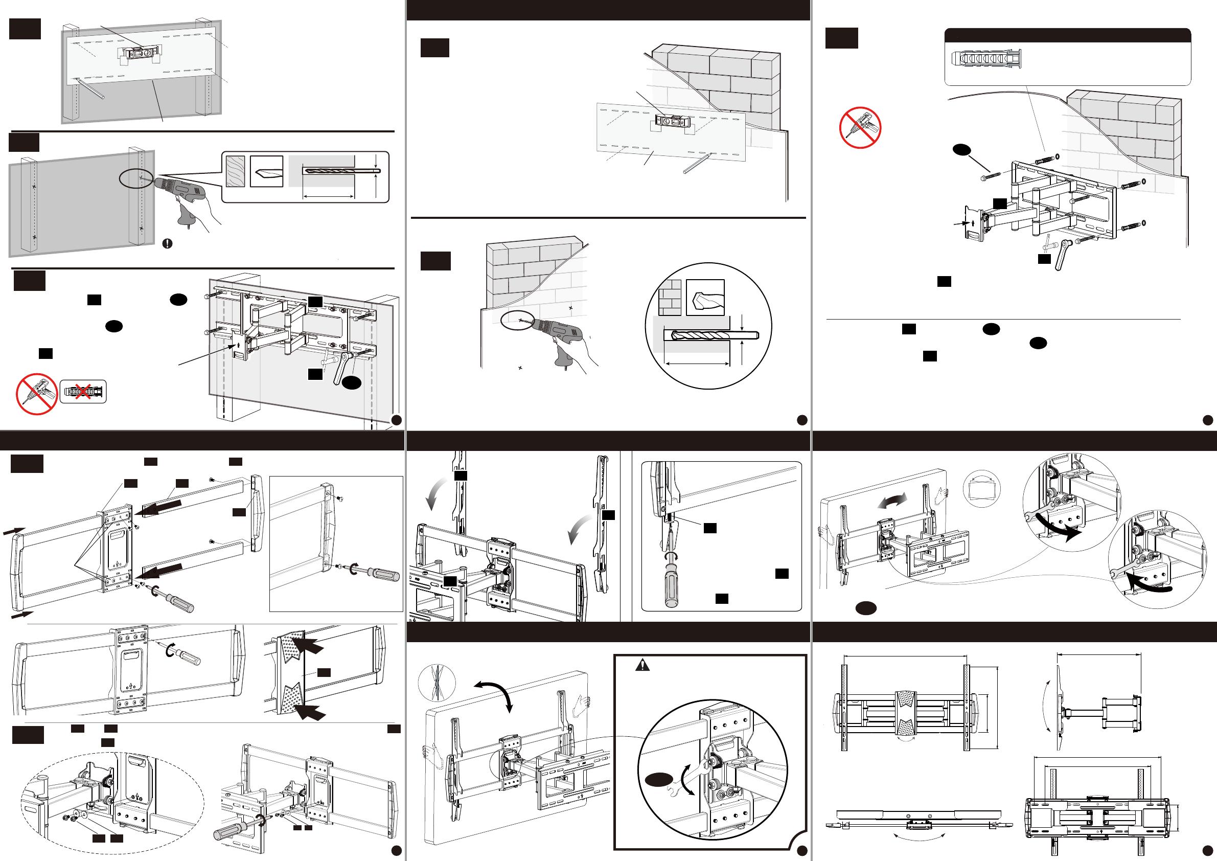
Secure TV with brackets
against the wall plate
with the pre-assembled
screws [S]
01
S3
[S3]
04
04
01
S3
Step 2B Wall plate installation (concrete or brick)
Drill pilot holes
2.75in 70 mm
Ø 10 mm
Ø 10 mm
3/8in
01 A
01
Install wall plate using lag bolts and anchor (not included) with Socket
Wrench, NO Electrodrill. Tighten the lag bolts until they are pulled firmly
against the wall plate
A
05
Use the included wrench when have not the socket wrench in hand.
05
A-3
A-4
7/32 in
Ø5.5 mm
2.75in (70 mm)
Drill pilot holes using a 7/32 in. (5.5 mm)
diameter drill bit.
IMPORTANT:
Pilot holes must be drilled to a depth
of 2 3/4 in (70 mm). Be sure to drill into the center of the stud.
2
A
Position the mounting template
at your desired height and line up
the holes with your stud center
line. Level the mounting template
and mark the pilot hole locations.
Mounting template
Bubble Level
A-5
To prevent the TV falling
down, the Arrow Must
Keep UP at this step!!
No!
V2
01 A
01
Install wall plate using lag bolts
with Socket Wrench, NO Electrodrill.
Tighten the lag bolts until they
are pulled firmly against the wall
plate
A
05
01
B-2
B-1 B-3
Contact us to have these additional pieces shipped
directly to you.
Concrete wall anchor 4pcs (NOT INCLUDED)
Ø10*61mm
Adjustments
Product dimensions:
Position the mounting template
at your desired height , level the
mounting template and mark the
pilot hole locations x4.
No!
2
Step 4 Hang TV with brackets onto the arm extensions
V2
A
To prevent the TV falling down, the
Arrow Must Keep UP at this step!!
Mounting template
Bubble Level
01
Adjustments







Step 3 Install front support and extensions
3-1
2. Remove the pre-assembled
screws x4
3. Insert the arm extension
Assemble the side covers and the arm
extensions with the preassembled screws
Install the extensions to front support with the pre-assembled screws.
03 02
Back view
1. Loosen a little
[02] [03]
02 03
[03]
06
07
Attach the front cover
to the front support
2. Push
1. Hang
Fasten the all 8 screws.
3-2 P1
P2
Hang 02 onto 01 and using a screwdriver to secure with pre-assembled screws
and washer .
02 01
P1 P2
P1 P2
-13°
+5°
Tilting Adjustment If necessary
B
Loosen
Tighten
If TV keeps tilting down, pull TV to desired
angle then fasten tilting nuts with open-end
wrench.
Loosen
Tighten
± 3°
TV leveling adjustment (-3°/+3°)
±3°
Loosen 2 leveling bolts on the rear of TV plate with the open- end
wrench , adjust to level, and retighten to secure.
B



76
8
11
10
9
  • Page 1 1
  • Page 2 2

MOUNTUP MU0028-24K User manual

Type
User manual

MOUNTUP MU0028-24K is a TV wall mount designed for TVs ranging from 24 to 55 inches and weighing up to 100 lbs. It features a full-motion design that allows for smooth tilting, swiveling, and extending of your TV, providing optimal viewing angles from any seat in the room. The mount also has a built-in cable management system to help keep your cords organized and out of sight. Easy to install with included hardware and step-by-step instructions, MOUNTUP MU0028-24K offers both safety and flexibility for your TV mounting needs.

Ask a question and I''ll find the answer in the document

Finding information in a document is now easier with AI