Page is loading ...

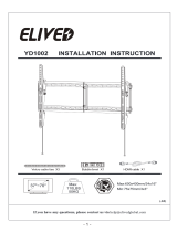
TOP OF TV
IJ
Horizontal
MA MB MC
ME
MD MF
1-3
Do not tighten the screws excessively or tighten them by
using the Electrodrill, or your TV might be damaged.
Not for
M8 Screws
May be needed
NOTE: Not all parts and hardware included will be used.
INSTALLATION INSTRUCTION
DWD902T-1_US3.0
Product Dimensions
TV Brackets
Wall Plate
x2
Hx1
I
x1
J
Wall Plate Cover
x1
K
Supplied Parts and Hardware
Tilting Adjustment
2
TV
Spacers
H10mm
×8
MD
Washers
Ф6mm
M4-5-6
×4
ME
Spacers
H5mm
×8
MF
Philips Screws
×4
MA
Philips Screws Philips Screws
×4 ×4
MB
×4 ×4
MC
×4
M4 x 12mm
M4 x 30mm
M6 x 15mm
M6 x 30mm
M8 x 25mm
M8 x 45mm
Velcro Cable Ties
Bubble Level
×1
T1 ×3
T2
Extra Tools You Need (Not Supplied)
Band
Tape
2M
Socket
Wrench
ScrewdriverPencil Electrodrill
1/2"
(13mm)
HammerMasonry
Drill Bit
For
Concrete Wall
Ф3/8"
(Ф10mm)
Stud
Finder
Awl Wood
Drill Bit
For
Wood Studs
Ф7/32"
(Ф5.5mm)
Please read this instruction carefully before installation. If you do not understand these
instructions or have doubts about the safety of the installation, assembly or use of this
product, please contact us.
● This product is designed for use in wood stud or solid concrete wall.
- DO NOT install into drywall alone.
● The wall must be capable of supporting five times the weight of the TV and mount combined.
● Incorrect installation may result in product damage / property damage or body injury.
We shall bear no responsibility for any damage or injury resulted from incorrect installation,
incorrect assembly or misuse.
WARNING: This product contains small items that could be a choking hazard if swallowed.
Before starting assembly, verify all parts are included and undamaged. If any parts are
missing or damaged, do not return the damaged item to your dealer; please contact our
customer service team. Never use damaged parts!
Safety Caution
If you have any questions, please feel free to contact Customer Service
via Amazon before returning.
Verify Your Wall Construction
MAX:
45 kg (99 lbs)
Load
Capacity
Must Check Before Getting Started
Minimum VESA Pattern (W × H):
150mm × 100mm / 6 in × 4 in
Maximum VESA Pattern (W × H):
600mm × 400mm / 24 in × 16 in
DO NOT install into drywall alone.
CAUTION:
CAUTION:
Avoid potential personal injuries and property damage!
Drywall covering the wall must not exceed 5/8 in. (16 mm).
Minimum wood stud size: nominal 2 x 4 in. (51 x 102 mm)
actual 1 ½ x 3 ½ in. (38 x 89 mm).
CAUTION:
Avoid potential personal injuries and property damage!
Mount the wall plate assembly directly onto the concrete
surface (no surface covering).
Min. 8"
(203mm)
Solid concrete wall
<5/8"(16mm)
Min.2"(51mm)
Min.4"(102mm)
Wall with wood studs
Max.24"(610mm)
Perfect!
Perfect!
cm
inches
W
H
MAX:600mm/24"
MIN:150mm/6"
MAX:
400mm/16"
MIN:
100mm/4"
420mm
/16.54"
88mm/3.46"
Φ
8.5mm/0.33"
25mm/0.98"
R4.3mm/0.17"
30mm/1.18"
200mm
/7.87"
147.5mm
/5.81"
668mm/26.3"
457mm/18"
406mm/16"
610mm/24"
42.5mm/1.67"
0°
-10 °
Tilt
Wall / Product
Wrench
S8mm/S10mm
x1
B
Nut
M6
x2
E
Washer
Ф6mm
x2
D
Bolt
M6x12mm
x2
C
Allen Key
4mm
x1
F
Yes, choose the appropriate screws, washers,and spacers for your TV.
TV back
Bracket
Long Screw
Spacer
Washer
No, just choose the screws, washers.
Bracket Washer
TV back
Short Screw
01 0302
For more spacing
between bracket
and TV
For protruded
back TV
For counterbore
of TV
To avoid the
blocked input
1-2 Need Spacer?
1-1 Select TV Screws
04
Attach Brackets to TV
1
M8
M6
M4
Correct Correct
Too LongToo Short Not Vertical
Lag Bolt
ST8x65mm
Ax4
Option: To keep TV in vertical position, please use two M4 screws (MA) to insert the
holes on two brackets respectively.
Tighten
Loosen
-10° 0°
Pull brackets to your desired
angle then fasten 2 tilting bolts
with Allen key (F).

A-3
A
A-1
Line up the holes with your stud
center line. Level the wall plate
and mark the pilot hole locations.
Locate your studs. Verify and mark
the center of the stud by finding the
stud edges using awl and stud finder.
Min. 2"
(51mm)
Min. 4"
(102mm)
Center line
Wall in front of
the wood studs
< 16mm (5/8")
T1
Wall Plate
Unit
B-1
Level the wall plate and
mark the pilot hole locations.
Min. 8"
(203mm)
T1
Wall Plate
Unit
B-2
2 ¾ in (70mm)
Ф3/8in
Ф10 mm
Deep
Bit
Concrete Wall
A-2
Ø7/32 in
Ø5.5 mm
2 ¾ in (70mm)
Deep
Bit
Wood Stud
B-3
A
Contact us to have
these additional pieces
shipped directly to you.
Ф10×61mm
Concrete Wall Anchor (NOT INCLUED)
5-2
5-1
Hang and Secure TV to Wall Plate
5
Hang and secure TV assembly onto the wall plate.
Before hanging TV, please conduct "wall plate installation integrity test" first.
Attach Wall Plate to Wall
4-B
OPTION B:
Solid Concrete Wall Installation
TV must be hung up
by two person
Attach Wall Plate to Wall
4-A
OPTION A:
Wood Stud Installation
If necessary
Take down the TV from the Mount
CAUTION:
Avoid potential personal injury
or property damage! Always
make sure your TV brackets are
in the locked position so the TV
is securely attached to the wall
plate assembly.
002862.eps
To avoid potential personal injury or property damage:
All 4 lag bolts MUST BE firmly tightened to prevent unwanted movement of
the wall plate assembly. Ensure the wall plate assembly is securely fastened to
the wall before continuing on to the next step.
A
CAUTION:
Install wall plate using lag bolts with Socket Wrench, NO Electrodrill.
No anchors when installed onto the wood studs.
AInstall wall plate using lag bolts and anchors (not included) with Socket
Wrench, NO Electrodrill.
A
Use the hammer to knock anchors (not included) into the concrete wall. Be sure
the anchors are seated flush with the concrete surface.
To avoid potential personal injury or property damage:
All 4 lag bolts MUST BE firmly tightened to prevent unwanted movement of
the wall plate assembly. Ensure the wall plate assembly is securely fastened to
the wall before continuing on to the next step.
A
CAUTION:
CAUTION: Do not use
in drywall or wood stud!
99 LBS (45 KG)
DANGERDANGER
Push it back to restore default settings before re-hangingback.
B
C
D
E
610mm / 24"
457mm / 18"
406mm / 16"
203mm / 8"
Assemble Wall Plate
3
Horizontal
3-1
Assemble two wall plates (H) with
bolts (C), washers (D) and nuts (E).
Keep the upside of the two wall
plates (H) horizontal, and then use
wrench (B) to fasten the nuts (E).
3-2
Buckle the Wall Plate Cover
(K) on the Wall Plate (H).
2. Push
1. Hang
K
Drill pilot holes using a
Ф7/32 in (Ф5.5mm) diameter drill bit.
IMPORTANT:
Do not drill holes into where water pipes
or electrical wires are located. Be sure to
drill into the center of the stud.
Drill pilot holes using a
Ф3/8 in (Ф10mm) diameter drill bit.
IMPORTANT:
Do not drill holes into where water pipes
or electrical wires are located, or mortar
between blocks.
Pull down the straps to
release the locking latch.
/