Page is loading ...

INSTALLATION INSTRUCTION
MODEL
:
MD2351
Please read this instruction carefully before installation
.
Thanks for your purchase! We strive to provide products and services of exceptional quality.
We sincerely invite you to write an unbiased review. For parts missed or installation problems,
please contact us at telephone
(
626
)
604-9048
(
USA
)
Mon-Fri 10am-6pm
(
Pacific time
)
or email us
by customerserv[email protected] , so that we may solve the issue for you.
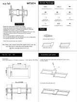
(A5)
Max VESA: 200 X 200 mm/7.87X7.87"
Installation Video
Fits for most 17-42 inches Plasma, LCD and LED TVs
.
Weight capacity: 30kg (66 lbs)
.

US
WARNING!
Safety Warning: Thank you for choosing Mounting Dream TV mount. For
safe application of model MD2351, and preventing yourself or others from
danger or property loss, please read through this manual before use. If
you do not understand these instructions or have any doubt over safety of
installation, please contact qualified contractor or Mounting Dream
customer service. Please check carefully before assembly to ensure no
parts missed or damaged. Our customer service representative will assist
you timely in installation to solve the issue of parts shortage or damage.
Replacement parts purchased through authorized distributor will be
delivered to your door. Please do not use defective parts. Incorrect
installation may result in product damage or body injury. Do not apply this
product to any purpose not indicated by Mounting Dream. We shall bear
no responsibility for any damage or injury resulted from incorrect
installation, incorrect assembly or misuse.
Advertencia de seguridad: Gracias por su opción del producto de soportes
para televisión de la marca Kongzhongshijie, para garantizar el uso en
seguro del modelo MD2351, evitar al usuario y otras personas sufriendo
riesgo de peligrosidad y daños a la propiedad, antes de usar , por favor,
lea bien este manual. Si usted no entiende estas instrucciones o existe
dudas sobre la seguridad de la instalación, por favor llame a un contratista
calificado o Centro de servicio al cliente, Antes de asemblar, verifique
cuidadosamente para asegurarse de que no encuentre la falta de piezas o
piezas defectuosos , nuestros representantes deservicio al cliente le
ayudará con rapidez para los problemas de instalación ,para resolver los
problemas de la falta y daño de las piezas. En el caso de que los
productos se vendan a través de distribuidores autorizados, las piezas de
repuestos serán entregados directamente a su domicilio , no utilice piezas
defectuosas , la instalación inadecuada puede causar daños o lesiones
graves. No utilizar este producto para cualquier otro propósito que fuera
de sus instrucciones, la compañía no es la responsable de los daños o las
pérdidas de la mala instalación , la asamblea incorrecta o uso incorrecto.
ADVERTENCIA!
ES

Before getting started, let's make sure this mount is
perfect for you!
1
Is your TV VESA equal to/greater than 75x75mm and equal
to/less than 200x200mm?
MAX:200mm
MAX:200mm
2
Does your TV (including accessories) weigh more than
66 lbs (30kg)?
66 lbs
(30kg)
NO --- Perfect!
Yes --- This mount is NOT compatible.
3
What is your wall made of?
CAUTION:
DO NOT install
into drywall alone
Perfect!
Drywall with
wood studs?
Solid concrete wall?
Yes --- Perfect!
No --- This mount is NOT compatible.
If this mount is NOT compatible, please contact
customerservice@mountingdream.com
to find a compatible mount.
Perfect!

For parts shortage or damage, please contact us directly by
customerservice@mountingdream.com.
New delivery
will be timely
arranged to replace missed or defective parts.
Attention:
Hammer
Bubble level Stud finder
2M
Band tape
2m
Pencil Screwdriver
Socket wrench
1/2"(13mm)
3/8"
Masonry Drill Bit
5/32"
Wood Drill Bit
Electrodrill
Installation tools:
HDMI cable
1pc
Velcro cable tie
2pcs
Bubble level
1pc
Gifts:
-Wall plate 1pc
-Bracket 2pcs
Part list:
①

For concrete wall installations ONLY
CAUTION:
Do not use in drywall or wood
Concrete Wall Anchor
4pcs
-Lag bolt
4pcs
Wall mounting hardware:
TV mounting hardware:
a--M4X12 bolt
4pcs
b--M5X12 bolt
4pcs
c--M6X12 bolt
4pcs
d--M8X25 bolt
4pcs
e--M4X30 bolt
4pcs
f--M5X30 bolt
4pcs
g--M6X35 bolt
4pcs
h--M8X50 bolt
4pcs
i--M5/M6 spacer
4pcs
j--M8 spacer
4pcs
k--M5/M4
washer 4pcs
l--M6 washer
4pcs
m--10mm
spacer 4pcs
n--2.5mm
spacer 8pcs
②

drywall with
wood stud
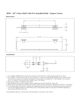
Step 1 Wall plate installation:
Option 1 Wall plate installation in wood stud
To avoid potential body injury or property damage:
1. Wall mount must be installed into wood stud's center, not drywall alone.
2. Drywall covering the wood stud must not exceed 16 mm (5/8 in.).
3. Minimum wood stud size: common 2 x 4 in(51 x 102 mm). Nominal 1 1/2 x 3 1/2 in(38 x 89mm)
4. The wall must be capable of supporting five times the weight of TV plus mount.
5. Make sure the logo on the wall plate is upward as the picture shows.
6. All lag bolts MUST BE firmly tightened to prevent unwanted movement of the wall plate.
Ensure the wall plate is securely fastened to the wall before continuing on to the next step.
Failure to follow this instruction will possibly lead to TV falling off from wall, and would possibly
cause body injuries or property loss.
⑤
④③
CAUTION
<16 mm(5/8 in.)
Locate the stud
with stud finder. Make
marks at the edges
of stud.
Mark centerlines
of stud.
②①
Make sure the logo on the wall plate is upward
The wall plate fits for single stud, 8” wood stud spacing, please choose corresponding holes in the wall plate for installation.
③
Put 2 lag bolts into the drilled holes, and
tighten each bolt by using a socket wrench to
mount the wall plate securely. Before totally
tightening the lag bolt please attach the bubble
level on the wall plate to check whether it is level.
Then place wall plate along the centerline and
use pencil to mark 2 hole locations on the wall.
Use 5/32" diameter drill bit to drill 2 pilot holes
at marked positions to a depth of 2.36".

To avoid potential personal injury or property damage:
1. Make sure the logo on the wall plate is upward as the picture shows.
2. Solid concrete wall's thickness should be more than 100mm/4", and the wall must be
capable of supporting five times the weight of the TV plus the mount.
3. All anchors/lag bolts MUST BE firmly tightened to prevent unwanted movement of the wall plate.
Ensure the wall plate is securely fastened to the wall before continuing on to the next step.
Option 2 Wall plate installation on concrete wall
①
②
③
CAUTION
Make sure the logo on the wall plate is upward
A
UP
Level the wall plate and use wall plate as a
template and pencil to mark 4 hole locations
on your desired height of the wall.
Use 3/8" diameter drill bit to drill 4 pilot holes
at marked positions to a depth of 2.36".
Put 4 Concrete Wall Anchors into drilled holes, and tap
each anchor flush with the wall by using a hammer.
Then put 4 lag bolts into the anchors, and tighten
each bolt by using a socket wrench to mount the wall
plate securely. Before totally tightening the lag bolt
please attach the bubble level on the wall plate to check
whether it is level.
Concrete wall
④

1
Step 2
Select TV hardware (diameter / length / combination)
Bolt diameter: hand thread bolts into threaded inserts on the back of
TV to determine correct bolt diameter (M4, M5, M6, M8).
Too Short
Bolt length: verify adequate thread engagement with bolts or
bolts/spacers combination.We recommend thread engagement
by at least 5 turns.
- Too short will not hold the TV.
- Too long will damage the TV.
Too Long Correct
2
Add distance to wall Irregular back Inset holes
Cables
Bolt and spacer combination: spacers sometimes are needed to
combine with bolts for several situations.
+
(For detail bolts and spacers combination, please refer to Page 7)
3
TV back
TV back
TV back
TV back
Carefully lay your TV on a non-abrasive surface, or lay it with a padding underneath
it so as not to damage the screen.
⑤

Step 3
Attach brackets to the back of the TV:
①
For the TV with flat back, mount the brackets with bolt/washer/spacer
combination.
Tips:
Make sure the ends of TV
brackets with round
holes are facing upward.
Round hole is for upper
VESA hole, and long slot
hole for lower VESA hole.
Please try best to locate
brackets symmetrically (top
& bottom) at the back of TV
to avoid brackets stick out.
Attention: Screw in bolts a
bit, then pull upward
brackets to reduce the gap
between bolts and bolt
holes to make two brackets
parallel. Then fasten bolts.
Carefully lay TV on a non-abrasive surface, or with a padding underneath it so as not to
damage the screen.
Bolt/spacer/washer combination options
(only for reference)
Tips:You have to remove the inner
circle of 2.5mm washer (n) in order
to fit the M8 (d) bolt.
⑥

②
For TV with irregular back, mount the brackets with bolt/washer/spacer
combination.
(Spacers are highly recommended to be added, thus enlarge the space
between TV and brackets for better functionality.)
Carefully lay TV on a non-abrasive surface, or with a padding underneath it so as not to
damage the screen.
Tips:
Make sure the ends of TV
brackets with round
holes are facing upward.
Round hole is for upper
VESA hole, and long slot
hole for lower VESA hole.
Please try best to locate
brackets symmetrically (top
& bottom) at the back of TV
to avoid brackets stick out.
Attention: Screw in bolts a
bit, then pull upward
brackets to reduce the gap
between bolts and bolt
holes to make two brackets
parallel. Then fasten bolts.
Bolt/spacer/washer combination options
(only for reference)
f
k
options
spacer
j
m
h
options
spacer
j
n
n
Tips: You have to remove the inner circle of 2.5mm washer (n) in order to fit the M6 (g)
or M8 (h) bolt.
⑦

Step 4
Hang the TV unit on the wall plate:
Hang the top hooks of the brackets over the top bar of the the
assembled wall mount. Make sure the hooks securely hang in
the bar ( figure 1) .
Then attach the lower ends of the brackets to the lower bar of
the wall mount.
When TV is at the desired place, fasten safety
screws
①
with a screwdriver until screws tightly lock the wall
bar
( figure 2)
.
figure 1
figure 2
Two people are recommended to
hold and position the TV. And
cables are recommended to plug
in before hanging the TV.
1
⑧

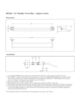
Product dimensions:
If you have any questions about the installation, please feel free to contact us at telephone (626) 604-9048 (USA)
Mon - Fri 10am - 6pm (Pacific time) or email us by customerservice@mountingdream.com .
For more information, please visit our website:www.mountingdream.com
Step 5
To take down the TV from the mount. You need loosen the
safety screws with a screwdriver. Then hold the TV upward to
unlock the top hooks from the top bar.
255mm
MAX:200mm
200mm
194mm
220mm
28mm
1
⑨
/