Cornelius 230 VAC User manual
- Category
- Water dispensers
- Type
- User manual
This manual is also suitable for

Installation/Service Manual
FCB POST-MIX DISPENSER
W/HOT-GAS DEFROST AND V4 ELECTRONICS
(DEFROST/ERROR INDICATOR LIGHTS)
IMPORTANT:
TO THE INSTALLER.
It is the responsibility of
the Installer to ensure that
the water supply to the
dispensing equipment is
provided with protection
against backflow by an air
gap as defined in
ANSI/ASME A112.1.2-1979;
or an approved vacuum
breaker or other such
method as proved effective
by test.
Water pipe connections
and fixtures directly
connected to a potable
water supply shall be
sized, installed, and
maintained according to
Federal, State, and Local
Codes.
PRINTED IN U.S.A
IMI CORNELIUS INC; 2004–2006©
IMI CORNELIUS INC
www.cornelius.com
Part No. 560001279SER
February 20, 2004
Revised: December 6, 2006
Revision: E
THIS DOCUMENT CONTAINS IMPORTANT INFORMATION
This Manual must be read and understood before installing or operating this equipment

TABLE OF CONTENTS
SAFETY INFORMATION 1. . . . . . . . . . . . . . . . . . . . . . . . . . . . . . . . . . . . . . . . . . . . . . . . . . . . . . .
RECOGNIZE SAFETY INFORMATION 1. . . . . . . . . . . . . . . . . . . . . . . . . . . . . . . . . . .
UNDERSTAND SIGNAL WORDS 1. . . . . . . . . . . . . . . . . . . . . . . . . . . . . . . . . . . . . . . .
FOLLOW SAFETY INSTRUCTIONS 1. . . . . . . . . . . . . . . . . . . . . . . . . . . . . . . . . . . . . .
CO2 (CARBON DIOXIDE) WARNING 1. . . . . . . . . . . . . . . . . . . . . . . . . . . . . . . . . . . . .
SHIPPING, STORING, OR RELOCATING UNIT 1. . . . . . . . . . . . . . . . . . . . . . . . . . .
GENERAL INFORMATION 2. . . . . . . . . . . . . . . . . . . . . . . . . . . . . . . . . . . . . . . . . . . . . . . . . . . . .
GENERAL DESCRIPTION 2. . . . . . . . . . . . . . . . . . . . . . . . . . . . . . . . . . . . . . . . . . . . . . . . . .
UNIT DESCRIPTION 3. . . . . . . . . . . . . . . . . . . . . . . . . . . . . . . . . . . . . . . . . . . . . . . . . . . . . . .
2 AND 3 H.P. TWO–FLAVOR OVERCOUNTER (OC2) UNITS 3. . . . . . . . . . . . . . .
TWO–FLAVOR FLOOR MODEL 3. . . . . . . . . . . . . . . . . . . . . . . . . . . . . . . . . . . . . . . . .
FOUR–FLAVOR FLOOR MODEL 4. . . . . . . . . . . . . . . . . . . . . . . . . . . . . . . . . . . . . . . .
REFRIGERATION SYSTEMS 6. . . . . . . . . . . . . . . . . . . . . . . . . . . . . . . . . . . . . . . . . . . .
THEORY OF OPERATION 7. . . . . . . . . . . . . . . . . . . . . . . . . . . . . . . . . . . . . . . . . . . . . . . . . .
DEFROST SYSTEMS 7. . . . . . . . . . . . . . . . . . . . . . . . . . . . . . . . . . . . . . . . . . . . . . . . . . . . . .
MANUAL DEFROST SYSTEM 7. . . . . . . . . . . . . . . . . . . . . . . . . . . . . . . . . . . . . . . . . . .
AUTOMATIC DEFROST SYSTEM 8. . . . . . . . . . . . . . . . . . . . . . . . . . . . . . . . . . . . . . .
‘‘SLEEP’’ (SLEEP TIME) 8. . . . . . . . . . . . . . . . . . . . . . . . . . . . . . . . . . . . . . . . . . . . . . . . . . . .
‘‘WAKE UP’’ (WAKE UP TIME) 8. . . . . . . . . . . . . . . . . . . . . . . . . . . . . . . . . . . . . . . . . . . . . .
INSTALLATION 11. . . . . . . . . . . . . . . . . . . . . . . . . . . . . . . . . . . . . . . . . . . . . . . . . . . . . . . . . . . . . . .
UNPACKING AND INSPECTION 11. . . . . . . . . . . . . . . . . . . . . . . . . . . . . . . . . . . . . . . . . . . .
IDENTIFICATION OF LOOSE-SHIPPED PARTS 12. . . . . . . . . . . . . . . . . . . . . . . . . . . . . .
SELECTING LOCATION 13. . . . . . . . . . . . . . . . . . . . . . . . . . . . . . . . . . . . . . . . . . . . . . . . . . . .
INSTALLING UNIT 13. . . . . . . . . . . . . . . . . . . . . . . . . . . . . . . . . . . . . . . . . . . . . . . . . . . . . . . . .
INSTALLING APPLICABLE CASTER KIT OR LEVELING LEGS 13. . . . . . . . . . . . . .
INSTALLING DRIP TRAY SUPPORTS 14. . . . . . . . . . . . . . . . . . . . . . . . . . . . . . . . . . . .
INSTALLING DRIP TRAY DRAIN KIT 14. . . . . . . . . . . . . . . . . . . . . . . . . . . . . . . . . . . . .
PLACING UNIT IN OPERATING LOCATION 14. . . . . . . . . . . . . . . . . . . . . . . . . . . . . . .
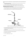
INSTALLING PRIMARY CO2 REGULATOR ASSEMBLY ON CO2 CYLINDER
(SEE APPLICABLE FIGURE 4 OR 5) 15. . . . . . . . . . . . . . . . . . . . . . . . . . . . . . . . .
CONNECTING SOFT DRINK TANKS CO2 LINES TO PRIMARY
CO2 REGULATOR ASSEMBLY (SEE APPLICABLE FIGURE 4 OR 5) 15. . . . .
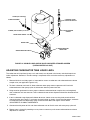
PREPARING UNIT SYRUP INLET LINES FOR CONNECTION TO SOFT
DRINK TANKS (SEE APPLICABLE FIGURE 4 OR 5) 15. . . . . . . . . . . . . . . . . . .
CONNECTING CITY PLAIN WATER SOURCE LINE (S) TO UNIT 15. . . . . . . . . . .
CONNECTING CO2 SOURCE LINE TO UNIT
(SEE APPLICABLE FIGURE 4 OR 5) 16. . . . . . . . . . . . . . . . . . . . . . . . . . . . . . . . .
CONNECTING ELECTRICAL POWER SOURCE TO UNIT 16. . . . . . . . . . . . . . . . .
PREPARATION FOR OPERATION 19. . . . . . . . . . . . . . . . . . . . . . . . . . . . . . . . . . . . . . . . . .
TWO–FLAVOR UNITS 19. . . . . . . . . . . . . . . . . . . . . . . . . . . . . . . . . . . . . . . . . . . . . . . . . .
FOUR–FLAVOR UNITS 19. . . . . . . . . . . . . . . . . . . . . . . . . . . . . . . . . . . . . . . . . . . . . . . . .
TURNING ON ELECTRICAL POWER TO UNIT 19. . . . . . . . . . . . . . . . . . . . . . . . . . . .
TURNING ON CO2 SUPPLY TO UNIT 19. . . . . . . . . . . . . . . . . . . . . . . . . . . . . . . . . . . .
ADJUSTING CO2 REGULATORS (SEE APPLICABLE FIGURE 4 OR 5) 20. . . . . .
TURNING ON CITY PLAIN WATER SOURCE LINE TO UNIT 20. . . . . . . . . . . . . . . .
ACTIVATING SYRUP SOURCE SYSTEM 21. . . . . . . . . . . . . . . . . . . . . . . . . . . . . . . . .
ADJUSTING BRIX (WATER-TO-SYRUP “RATIO”) OF DISPENSED PRODUCT 21
FILLING FREEZE CYLINDERS WITH PRODUCT 22. . . . . . . . . . . . . . . . . . . . . . . . . .

CHECKING UNIT FOR SYRUP, CO2 AND PLAIN WATER LEAKS 22. . . . . . . . . . .
ADJUSTING “WATER-COOLED” UNIT REFRIGERATION SYSTEM
VARIABLE WATER REGULATOR 22. . . . . . . . . . . . . . . . . . . . . . . . . . . . . . . . . . . .
ADJUSTMENTS AND PROGRAMMING PROCEDURES 22. . . . . . . . . . . . . . . . . . . . . . .
SETTING CLOCK (TIME OF DAY) 23. . . . . . . . . . . . . . . . . . . . . . . . . . . . . . . . . . . . . . .
PROGRAMMING DEFROST (AUTOMATIC) INTO UNIT ELECTRONICS 23. . . . .
PROGRAMMING “SLEEP” (SLEEP TIME) INTO UNIT ELECTRONICS 23. . . . . . .
PROGRAMMING “WAKE UP” (WAKE UP TIME) INTO
UNIT ELECTRONICS 23. . . . . . . . . . . . . . . . . . . . . . . . . . . . . . . . . . . . . . . . . . . . . . .
PROGRAMMING POINT OF SALE MESSAGE DISPLAY INTO UNIT
ELECTRONICS 23. . . . . . . . . . . . . . . . . . . . . . . . . . . . . . . . . . . . . . . . . . . . . . . . . . . .
ADJUSTING “VIS SET” (PRODUCT VISCOSITY) OF
DISPENSED PRODUCT 23. . . . . . . . . . . . . . . . . . . . . . . . . . . . . . . . . . . . . . . . . . . .
“VIS READ” (ACTUAL VISCOSITY READOUT) OF
PRODUCT IN FREEZE CYLINDERS 24. . . . . . . . . . . . . . . . . . . . . . . . . . . . . . . . . .
DISPLAYED EVAPORATOR REFRIGERATION COILS INLETS AND
COMMON OUTLET SENSORS TEMPERATURES 24. . . . . . . . . . . . . . . . . . . . .
“VOLTAGE” (DISPLAYED VOLTAGE READOUT) 24. . . . . . . . . . . . . . . . . . . . . . . . . .
PROGRAMMING COMPONENTS “DIAGNOSE” (DIAGNOSTIC MODE)
INTO UNIT 24. . . . . . . . . . . . . . . . . . . . . . . . . . . . . . . . . . . . . . . . . . . . . . . . . . . . . . . .
DISPLAYING “TOTALS” (DISPLAYED CYCLES AND HOURS TOTALS)
ONTO MESSAGE DISPLAY 24. . . . . . . . . . . . . . . . . . . . . . . . . . . . . . . . . . . . . . . . .
PROGRAMMING FREEZE CYLINDERS BEATER “MOTORS”
INTO UNIT ELECTRONICS 24. . . . . . . . . . . . . . . . . . . . . . . . . . . . . . . . . . . . . . . . . .
PROGRAMMING PROPER REFRIGERANT TYPE INTO UNIT
ELECTRONICS 24. . . . . . . . . . . . . . . . . . . . . . . . . . . . . . . . . . . . . . . . . . . . . . . . . . . .
“OPTIONS” (DIP SWITCHES 1 THROUGH 10) 25. . . . . . . . . . . . . . . . . . . . . . . . . . . .
PROGRAMMING CALENDAR INTO UNIT ELECTRONICS 25. . . . . . . . . . . . . . . . . .
PROGRAMMING DST+1HR INTO UNIT ELECTRONICS 25. . . . . . . . . . . . . . . . . . .
PROGRAMMING DST–1HR INTO UNIT ELECTRONICS 25. . . . . . . . . . . . . . . . . . .
DISPLAYED ERROR CONDITIONS 26. . . . . . . . . . . . . . . . . . . . . . . . . . . . . . . . . . . . . .
ADJUSTING BEATER MOTOR CURRENT (EITHER SIDE) 26. . . . . . . . . . . . . . . . .
PROGRAMMING/ADJUSTMENTS 29. . . . . . . . . . . . . . . . . . . . . . . . . . . . . . . . . . . . . . . . . . . . . .
OPERATOR’S INSTRUCTIONS 37. . . . . . . . . . . . . . . . . . . . . . . . . . . . . . . . . . . . . . . . . . . . . . . . .
MAINTAINING PRODUCT QUALITY
CORNELIUS FCB EQUIPMENT - OPERATOR INSTRUCTIONS 37. . . . . . . . . . . . .
1. DISPENSED PRODUCT THROUGHPUT 37. . . . . . . . . . . . . . . . . . . . . . . . . . . . . . .
2. PROGRAMMED DEFROST SCHEDULING 38. . . . . . . . . . . . . . . . . . . . . . . . . . . . .
3. VISCOSITY SETTING 38. . . . . . . . . . . . . . . . . . . . . . . . . . . . . . . . . . . . . . . . . . . . . . . .
FRONT ACCESS DOOR INDICATOR LIGHTS (SEE FIGURE 8) 38. . . . . . . . . . . . . . . .
TWO–FLAVOR UNITS 38. . . . . . . . . . . . . . . . . . . . . . . . . . . . . . . . . . . . . . . . . . . . . . . . . .
FOUR–FLAVOR UNITS 39. . . . . . . . . . . . . . . . . . . . . . . . . . . . . . . . . . . . . . . . . . . . . . . . .
CONTROL PANEL (KEYPAD) SECURITY 39. . . . . . . . . . . . . . . . . . . . . . . . . . . . . . . . . . . .
CONTROL PANEL SWITCHES (SEE FIGURE 9) 39. . . . . . . . . . . . . . . . . . . . . . . . . . . . . .
‘‘SYRUP PRIME’’ SWITCHES 40. . . . . . . . . . . . . . . . . . . . . . . . . . . . . . . . . . . . . . . . . . .
‘‘BLEND ON/OFF’’ SWITCHES 40. . . . . . . . . . . . . . . . . . . . . . . . . . . . . . . . . . . . . . . . . .
‘‘MOTOR’’ SWITCHES 40. . . . . . . . . . . . . . . . . . . . . . . . . . . . . . . . . . . . . . . . . . . . . . . . . .
“ON’’ SWITCHES 40. . . . . . . . . . . . . . . . . . . . . . . . . . . . . . . . . . . . . . . . . . . . . . . . . . . . . .
‘‘OFF’’ SWITCHES 40. . . . . . . . . . . . . . . . . . . . . . . . . . . . . . . . . . . . . . . . . . . . . . . . . . . . .
‘‘ERROR RESET’’ SWITCH 40. . . . . . . . . . . . . . . . . . . . . . . . . . . . . . . . . . . . . . . . . . . . .
CONTROL PANEL DISPLAY MESSAGES 41. . . . . . . . . . . . . . . . . . . . . . . . . . . . . . . . . . . .

‘‘FILL 1’’ AND ‘‘FILL 2’’ FAULT MESSAGES 41. . . . . . . . . . . . . . . . . . . . . . . . . . . . . . . .
‘‘ERROR 1’’ AND ‘‘ERROR 2’’ FAULT MESSAGES 41. . . . . . . . . . . . . . . . . . . . . . . . .
‘‘OFF 1’’ AND ‘‘OFF 2’’ FAULT MESSAGES 41. . . . . . . . . . . . . . . . . . . . . . . . . . . . . . . .
‘‘H2O OUT’’ FAULT MESSAGE 41. . . . . . . . . . . . . . . . . . . . . . . . . . . . . . . . . . . . . . . . . .
‘‘CO2 OUT’’ FAULT MESSAGE 41. . . . . . . . . . . . . . . . . . . . . . . . . . . . . . . . . . . . . . . . . .
‘‘SYRUP 1’’ OR ‘‘SYRUP 2’’ FAULT MESSAGES 41. . . . . . . . . . . . . . . . . . . . . . . . . . .
‘‘DEFROST 1’’ OR ‘‘DEFROST 2’’ DISPLAY MESSAGES 41. . . . . . . . . . . . . . . . . . .
‘‘POINT OF SALE’’ DISPLAY MESSAGES 41. . . . . . . . . . . . . . . . . . . . . . . . . . . . . . . . .
DEFROST SYSTEMS 42. . . . . . . . . . . . . . . . . . . . . . . . . . . . . . . . . . . . . . . . . . . . . . . . . . . . . .
MANUAL DEFROST SYSTEM 42. . . . . . . . . . . . . . . . . . . . . . . . . . . . . . . . . . . . . . . . . . .
AUTOMATIC DEFROST SYSTEM 42. . . . . . . . . . . . . . . . . . . . . . . . . . . . . . . . . . . . . . .
‘‘SLEEP’’ (SLEEP TIME) 42. . . . . . . . . . . . . . . . . . . . . . . . . . . . . . . . . . . . . . . . . . . . . . . . . . . .
‘‘WAKE UP’’ (WAKE UP TIME) 42. . . . . . . . . . . . . . . . . . . . . . . . . . . . . . . . . . . . . . . . . . . . . .
FACEPLATE RELIEF VALVES 43. . . . . . . . . . . . . . . . . . . . . . . . . . . . . . . . . . . . . . . . . . . . . . .
DISPENSING VALVES 43. . . . . . . . . . . . . . . . . . . . . . . . . . . . . . . . . . . . . . . . . . . . . . . . . . . . .
DISPENSED PRODUCT CONDITIONS 43. . . . . . . . . . . . . . . . . . . . . . . . . . . . . . . . . . . . . .
‘‘OVERRUN’’, AS APPLIED TO FROZEN CARBONATED BEVERAGES 43. . . . . .
OPERATING CHARACTERISTICS 45. . . . . . . . . . . . . . . . . . . . . . . . . . . . . . . . . . . . . . . . . .
UNIT OPERATION 45. . . . . . . . . . . . . . . . . . . . . . . . . . . . . . . . . . . . . . . . . . . . . . . . . . . . . . . . .
ADJUSTING CO2 REGULATORS 45. . . . . . . . . . . . . . . . . . . . . . . . . . . . . . . . . . . . . . . . . . .
PRIMARY CO2 REGULATOR 45. . . . . . . . . . . . . . . . . . . . . . . . . . . . . . . . . . . . . . . . . . .
SECONDARY CO2 REGULATORS 45. . . . . . . . . . . . . . . . . . . . . . . . . . . . . . . . . . . . . . .
ADJUSTING BRIX (WATER-TO-SYRUP “RATIO”) OF DISPENSED PRODUCT 46. . .
REPLENISHING SYRUP SUPPLY 46. . . . . . . . . . . . . . . . . . . . . . . . . . . . . . . . . . . . . . . . . . .
SYRUP FLAVOR CHANGE 46. . . . . . . . . . . . . . . . . . . . . . . . . . . . . . . . . . . . . . . . . . . . . . . . .
REPLENISHING CO2 SUPPLY 46. . . . . . . . . . . . . . . . . . . . . . . . . . . . . . . . . . . . . . . . . . . . . .
CLEANING AND SANITIZING 46. . . . . . . . . . . . . . . . . . . . . . . . . . . . . . . . . . . . . . . . . . . . . . .
DAILY CLEANING OF UNIT 46. . . . . . . . . . . . . . . . . . . . . . . . . . . . . . . . . . . . . . . . . . . . .
SANITIZING SYRUP SYSTEMS 46. . . . . . . . . . . . . . . . . . . . . . . . . . . . . . . . . . . . . . . . .
CLEANING CONDENSER COIL 46. . . . . . . . . . . . . . . . . . . . . . . . . . . . . . . . . . . . . . . . . . . . .
SERVICE AND MAINTENANCE 47. . . . . . . . . . . . . . . . . . . . . . . . . . . . . . . . . . . . . . . . . . . . . . . .
PREPARING UNIT FOR SHIPPING, STORING, OR RELOCATING 47. . . . . . . . . . . . .
PERIODIC INSPECTION 47. . . . . . . . . . . . . . . . . . . . . . . . . . . . . . . . . . . . . . . . . . . . . . . . . . .
REMOVAL OF PANELS 47. . . . . . . . . . . . . . . . . . . . . . . . . . . . . . . . . . . . . . . . . . . . . . . . . . . .
DRIP TRAY 47. . . . . . . . . . . . . . . . . . . . . . . . . . . . . . . . . . . . . . . . . . . . . . . . . . . . . . . . . . .
BACK PANEL 47. . . . . . . . . . . . . . . . . . . . . . . . . . . . . . . . . . . . . . . . . . . . . . . . . . . . . . . . . .
SIDE PANELS 47. . . . . . . . . . . . . . . . . . . . . . . . . . . . . . . . . . . . . . . . . . . . . . . . . . . . . . . . .
TOP PANEL 47. . . . . . . . . . . . . . . . . . . . . . . . . . . . . . . . . . . . . . . . . . . . . . . . . . . . . . . . . . .
LOWER FRONT ACCESS PANEL 47. . . . . . . . . . . . . . . . . . . . . . . . . . . . . . . . . . . . . . .
CONDENSER COIL ACCESS PANEL 47. . . . . . . . . . . . . . . . . . . . . . . . . . . . . . . . . . . .
OPENING AND CLOSING FRONT ACCESS DOOR 48. . . . . . . . . . . . . . . . . . . . . . . . . . .
TWO–FLAVOR MODELS AND OVERCOUNTER (OC2) MODELS 48. . . . . . . . . . .
FOUR–FLAVOR FLOOR MODEL 48. . . . . . . . . . . . . . . . . . . . . . . . . . . . . . . . . . . . . . . .
ADJUSTMENTS 48. . . . . . . . . . . . . . . . . . . . . . . . . . . . . . . . . . . . . . . . . . . . . . . . . . . . . . . . . . .
ADJUSTING PLAIN WATER PRESSURE REGULATOR
(SEE APPLICABLE FIGURE 4 OR 5) 48. . . . . . . . . . . . . . . . . . . . . . . . . . . . . . . . .
ADJUSTING CARBONATED WATER FLOW RATE
(SEE APPLICABLE FIGURE 4 OR 5 AND 16) 48. . . . . . . . . . . . . . . . . . . . . . . . . .
PRODUCT CARBONATION ADJUSTMENT
(SEE APPLICABLE FIGURE 4 OR 5) 49. . . . . . . . . . . . . . . . . . . . . . . . . . . . . . . . .

SERVICING DISPENSING VALVES CAGED O-RINGS AND
FREEZE CYLINDERS DRIVE SHAFT/ SEAL ASSEMBLIES 50. . . . . . . . . . . . . . . . .
SERVICING DISPENSING VALVES CAGED O-RINGS. (SEE FIGURE 10) 50. . . .
SERVICING FREEZE CYLINDERS DRIVE SHAFT/SEAL ASSEMBLIES. 52. . . . .
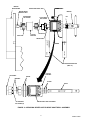
CLEANING CONDENSER COIL (SEE FIGURE 23) 55. . . . . . . . . . . . . . . . . . . . . . . . . . . .
UNIT WITH AIR-COOLED REFRIGERATION SYSTEM 55. . . . . . . . . . . . . . . . . . . . .
UNIT WITH WATER-COOLED REFRIGERATION SYSTEM 55. . . . . . . . . . . . . . . . .
CLEANING AND SANITIZING 55. . . . . . . . . . . . . . . . . . . . . . . . . . . . . . . . . . . . . . . . . . . . . . .
DAILY CLEANING OF UNIT 55. . . . . . . . . . . . . . . . . . . . . . . . . . . . . . . . . . . . . . . . . . . . .
SANITIZING SYRUP SYSTEMS 55. . . . . . . . . . . . . . . . . . . . . . . . . . . . . . . . . . . . . . . . .
YEARLY OR AFTER WATER SYSTEM DISRUPTION 58. . . . . . . . . . . . . . . . . . . . . . . . . .
SERVICING CARBONATOR WATER PUMP WATER STRAINER SCREEN
(2 AND 3 H.P. OVERCOUNTER UNITS) 58. . . . . . . . . . . . . . . . . . . . . . . . . . . . . . .
REPLACING CARBONATOR WATER PUMP DOUBLE LIQUID
CHECK VALVE (SEE APPLICABLE FIGURE 4 OR 5 AND 14 OR 15) 59. . . . .
ADJUSTING CARBONATOR TANK LIQUID LEVEL 60. . . . . . . . . . . . . . . . . . . . . . . . . . . .
REPLACING FREEZE CYLINDER BEATER DRIVE MOTOR (SEE FIGURE13) 61. . . .
REPLENISHING SYRUP SUPPLY 62. . . . . . . . . . . . . . . . . . . . . . . . . . . . . . . . . . . . . . . . . . .
SYRUP TANKS SYSTEM 62. . . . . . . . . . . . . . . . . . . . . . . . . . . . . . . . . . . . . . . . . . . . . . .
BAG–IN–BOX SYSTEM 63. . . . . . . . . . . . . . . . . . . . . . . . . . . . . . . . . . . . . . . . . . . . . . . . .
REPLENISHING CO2 SUPPLY 64. . . . . . . . . . . . . . . . . . . . . . . . . . . . . . . . . . . . . . . . . . . . . .
SYRUP FLAVOR CHANGE 65. . . . . . . . . . . . . . . . . . . . . . . . . . . . . . . . . . . . . . . . . . . . . . . . .
CLEANING CO2 SYSTEM GAS CHECK VALVES
(SEE APPLICABLE FIGURE 4 OR 5 AND 18) 65. . . . . . . . . . . . . . . . . . . . . . . . . . . . .
TROUBLESHOOTING 72. . . . . . . . . . . . . . . . . . . . . . . . . . . . . . . . . . . . . . . . . . . . . . . . . . . . . . . . .
WARRANTY 79. . . . . . . . . . . . . . . . . . . . . . . . . . . . . . . . . . . . . . . . . . . . . . . . . . . . . . . . . . . . . . . . . .
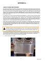
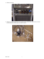
APPENDIX A 80. . . . . . . . . . . . . . . . . . . . . . . . . . . . . . . . . . . . . . . . . . . . . . . . . . . . . . . . . . . . . . . . .
VALVE TORQUE AND STAKING 80. . . . . . . . . . . . . . . . . . . . . . . . . . . . . . . . . . . . . . . . . . . .
MOTORMAN VALVE 82. . . . . . . . . . . . . . . . . . . . . . . . . . . . . . . . . . . . . . . . . . . . . . . . . . .
DELTA VALVE 84. . . . . . . . . . . . . . . . . . . . . . . . . . . . . . . . . . . . . . . . . . . . . . . . . . . . . . . . .

FIGURE 1. TWO–FLAVOR FLOOR MODEL 2. . . . . . . . . . . . . . . . . . . . . . . . . . . . . . . . . . . . . . . . .
FIGURE 2. TWO–FLAVOR OVERCOUNTER (OC2) UNIT 2. . . . . . . . . . . . . . . . . . . . . . . . . . . . .
FIGURE 3. FOUR–FLAVOR FLOOR MODEL 2. . . . . . . . . . . . . . . . . . . . . . . . . . . . . . . . . . . . . . . .
FIGURE 4. FLOW DIAGRAM. 3 H.P. DISPENSER (TWO–FLAVOR MODEL SHOWN) 9. . . .
FIGURE 5. FLOW DIAGRAM (2 AND 3 H.P. OVERCOUNTER OC2 DISPENSER) 10. . . . . . . .
FIGURE 6. CONTROL PANEL SWITCH/MESSAGE DISPLAY 27. . . . . . . . . . . . . . . . . . . . . . . . .
FIGURE 7. MASTER AND RELAY CIRCUIT BOARD 28. . . . . . . . . . . . . . . . . . . . . . . . . . . . . . . . .
FIGURE 8. FRONT ACCESS DOOR INDICATOR LIGHTS 39. . . . . . . . . . . . . . . . . . . . . . . . . . . .
FIGURE 9. CONTROL PANEL SWITCH IDENTIFICATION 39. . . . . . . . . . . . . . . . . . . . . . . . . . . .
FIGURE 10. SELF-CLOSING DISPENSING VALVE 50. . . . . . . . . . . . . . . . . . . . . . . . . . . . . . . . . .
FIGURE 11. FREEZE CYLINDER CUTAWAY VIEW 51. . . . . . . . . . . . . . . . . . . . . . . . . . . . . . . . . .
FIGURE 12. BEATERS AND SCRAPER BLADES INSTALLATION 53. . . . . . . . . . . . . . . . . . . . . .
FIGURE 13. SERVICING BEATER MOTOR DRIVE SHAFT/SEAL ASSEMBLY 54. . . . . . . . . . .
FIGURE 14. DOUBLE LIQUID CHECK VALVE (3 H.P. FLOOR MODEL UNIT) 59. . . . . . . . . . .
FIGURE 15. DOUBLE LIQUID CHECK VALVE AND WATER STRAINER SCREEN
(OVERCOUNTER OC2 UNIT) 60. . . . . . . . . . . . . . . . . . . . . . . . . . . . . . . . . . . . . . . . . . . . . .
FIGURE 16. PARTS IDENTIFICATION 62. . . . . . . . . . . . . . . . . . . . . . . . . . . . . . . . . . . . . . . . . . . . . .
FIGURE 17. CARBONATOR LIQUID LEVEL CONTROL SWITCH ADJUSTMENT 64. . . . . . . .
FIGURE 18. CO2 GAS CHECK VALVE 65. . . . . . . . . . . . . . . . . . . . . . . . . . . . . . . . . . . . . . . . . . . . . .
FIGURE 19. WIRING DIAGRAM (3 H.P. FLOOR MODEL UNIT) 66. . . . . . . . . . . . . . . . . . . . . . . .
FIGURE 20. WIRING DIAGRAM (2 AND 3 H.P. OVERCOUNTER OC2 UNITS) 67. . . . . . . . . .
FIGURE 21. WIRING DIAGRAM (TWO–FLAVOR UNITS) 68. . . . . . . . . . . . . . . . . . . . . . . . . . . . .
FIGURE 22. WIRING DIAGRAM (FOUR–FLAVOR UNITS) 69. . . . . . . . . . . . . . . . . . . . . . . . . . . .
FIGURE 23. REFRIGERATION FLOW DIAGRAM (AIR-COOLED REFRIGERATION
SYSTEM) 70. . . . . . . . . . . . . . . . . . . . . . . . . . . . . . . . . . . . . . . . . . . . . . . . . . . . . . . . . . . . . . . .
FIGURE 24. REFRIGERATION FLOW DIAGRAM (WATER-COOLED REFRIGERATION
SYSTEM) 71. . . . . . . . . . . . . . . . . . . . . . . . . . . . . . . . . . . . . . . . . . . . . . . . . . . . . . . . . . . . . . . .

560001279SER 1
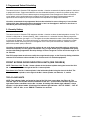
SAFETY INFORMATION
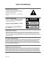
Recognize Safety Information
This is the safety-alert symbol. When you see this
symbol on our machine or in this manual, be alert to
the potentially of personal injury.
Follow recommended precautions and safe operating
practices.
DANGER
Understand Signal Words
A signal word - DANGER, WARNING, OR CAUTION
is used with the safety-alert symbol. DANGER identi-
fies the most serious hazards.
Safety signs with signal word DANGER or WARNING
are typically near specific hazards.
WARNING
General precautions are listed on CAUTION safety
signs. CAUTION also calls attention to safety mes-
sages in this manual.
CAUTION
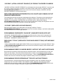
Follow Safety Instructions
Carefully read all safety messages in this manual and on your machine safety signs. Keep safety signs in
good condition. Replace missing or damaged safety signs. Learn how to operate the machine and how to
use the controls properly. Do not let anyone operate the machine without instructions. Keep your machine in
proper working condition. Unauthorized modifications to the machine may impair function and/or safety and
affect the machine life.
CO
2
(Carbon Dioxide) Warning
CO
2
Displaces Oxygen. Strict Attention must be observed in the prevention of CO
2
(carbon dioxide)
gas leaks in the entire CO
2
and soft drink system. If a CO
2
gas leak is suspected, particularly in a
small area, immediately ventilate the contaminated area before attempting to repair the leak. Person-
nel exposed to high concentration of CO
2
gas will experience tremors which are followed rapidly by
loss of consciousness and suffocation.
CAUTION: Before shipping, storing, or relocating the Unit, syrup systems must be sanitized and all
sanitizing solution must be purged from the syrup systems. All water must also be purged from the
plain and carbonated water systems. A freezing ambient environment will cause residual sanitizing
solution or water remaining inside the Unit to freeze resulting in damage to the internal components.
Shipping, Storing, Or Relocating Unit

560001279SER
2
GENERAL INFORMATION
IMPORTANT: To the user of this manual - This manual is a guide for installing, operating, and
maintaining this equipment. Refer to Table of Contents for page location of information pertaining to
questions that arise during installation, operation, service and maintenance, or troubleshooting this
equipment.
Warranty Registration Date
(to be filled out by customer)
Model Number:
Serial Number:
Install Date:
Local Authorized
Service Center:
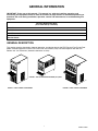
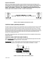
GENERAL DESCRIPTION
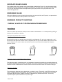
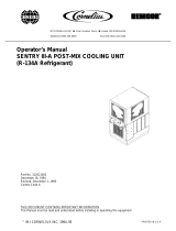
This section gives the description, theory of operation, and design data for the FCB Two and Four-Flavor Floor
Model Post-Mix Dispenser and the FCB Two-Flavor Overcounter (OC2) Post-Mix Dispenser with Hot-Gas
Defrost and V4+ Electronics (hereafter referred to as Units).
FIGURE 1. TWO–FLAVOR FLOOR MODEL
FIGURE 2. TWO–FLAVOR OVERCOUNTER (OC2) UNIT
FIGURE 3. FOUR–FLAVOR FLOOR MO
D

560001279SER 3
UNIT DESCRIPTION
2 AND 3 H.P. TWO–FLAVOR OVERCOUNTER (OC2) UNITS
The 2 and 3 H.P. Two–Flavor FCB Overcounter (OC2) Dispensers (see Figure 2 and Figure 5) consists
basically of two freeze cylinders each containing an internal beater driven by an electric motor, one refrigeration
system, one carbonator Tanks which feed both product blender tanks, a timer-controlled automatic hot-gas
defrost system to defrost the freeze cylinders, and interconnecting tubing, components, and fittings necessary
to regulate, transfer, and dispense product.
The Dispensers are equipped with V4 electronics and are also equipped with two indicator lights located on the
front access door of the Unit. The purpose of the indicator lights is to inform the Operator if one or both of the
freeze cylinders is in the defrost mode and also if an “OUT OF SYRUP”, “OUT OF WATER”, “OUT OF CO
2
”, or
if an error condition exist.
The components are attached to a steel frame and are enclosed in a steel cabinet. The cabinet panels are
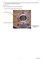
easily removed to facilitate installation and service and maintenance. A transparent faceplate, with an integral
relief valve and a removable self-closing dispensing valve, is mounted on front of each freeze cylinder. A
removable drip tray, with cup rest, is located directly below the dispensing valves.
TWO–FLAVOR FLOOR MODEL
The 3 H.P. Two–Flavor Floor Model FCB Dispenser (see Figure 1 and 4) consists basically of two freeze
cylinders each containing an internal beater driven by an electric motor, one refrigeration system, two product
blender tanks, two carbonator tanks which feed both product blender tanks, a timer-controlled automatic hot-gas
defrost system to defrost the freeze cylinders, and interconnecting tubing, components, and fittings necessary
to regulate, transfer, and dispense product.
The Unit is equipped with V4 electronics and is also equipped with two indicator lights located on the front
access door of the Unit. The purpose of the indicator lights is to inform the Operator if one or both of the freeze
cylinders is in the defrost mode and also if an “OUT OF SYRUP”, “OUT OF WATER”, “OUT OF CO
2
”, or if an
error condition exist.
The components are attached to a steel frame and are enclosed in a steel cabinet. The cabinet panels are
easily removed to facilitate installation and service and maintenance. A transparent faceplate, with an integral
relief valve and a removable self-closing dispensing valve, is mounted on front of each freeze cylinder. A
removable drip tray, with cup rest, is located directly below the dispensing valves.

560001279SER
4
FOUR–FLAVOR FLOOR MODEL
The 2 H.P. Four–Flavor Floor Model FCB Dispenser (see Figure 3 and 4) consists basically of four freeze
cylinders each containing an internal beater driven by an electric motor, two refrigeration systems, four product
blender tanks, four carbonator tanks which feed the product blender tanks, a timer-controlled automatic hot-gas
defrost system to defrost the freeze cylinders, and interconnecting tubing, components, and fittings necessary
to regulate, transfer, and dispense product.
The Unit is equipped with V4 electronics and is also equipped with four indicator lights located on the front
access door of the Unit. The purpose of the indicator lights is to inform the Operator if the freeze cylinders are in
the defrost mode and also if an “OUT OF SYRUP”, “OUT OF WATER”, “OUT OF CO
2
”, or if an error condition
exist.
The components are attached to a steel frame and are enclosed in a steel cabinet. The cabinet panels are
easily removed to facilitate installation and service and maintenance. A transparent faceplate, with an integral
relief valve and a removable self-closing dispensing valve, is mounted on front of each freeze cylinder. A
removable drip tray, with cup rest, is located directly below the dispensing valves.
CAUTION: Before shipping, storing, or relocating the Unit, the syrup systems must be
sanitized and all sanitizing solution must be purged from the syrup systems. All water must
also be purged from the plain and carbonated water systems. A freezing ambient
environment will cause residual sanitizing solution or water remaining inside the Unit to freeze
resulting in damage to the internal components.

560001279SER 5
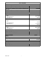
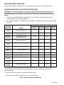
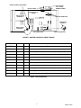
Table 1. Design Data
Unit Part Numbers:
Two-Flavor 3 H.P. Floor Model (Air-Cooled), 230 VAC, 60 Hz 4166201000
Two-Flavor 3 H.P. Floor Model (Water-Cooled) 230 VAC, 60 Hz 4166221000
Two-Flavor 2 H.P. Overcounter (OC2) Air-Cooled 230 VAC, 60 Hz 4161361000
Two-Flavor 3 H.P. Overcounter (OC2) Air-Cooled (Top Condensing) 230
VAC, 60 Hz
4161367000
Two-Flavor 3 H.P. Overcounter (OC2) Water-Cooled 230 VAC, 60 Hz 4161362000
Four-Flavor 2 H.P. Floor Model Air-Cooled 230 VAC, 60 Hz 4166001000
Overall Dimensions:
Two-Flavor Floor Model
Height
Width
Depth (W/O Drip Tray)
Depth W/Drip Tray
60-1/2 inches
19-1/4 inches
32-1/2 inches
38 inches
Two-Flavor Overcounter (OC2) Model
Height
Width
Depth (W/O Drip Tray)
Depth W/Drip Tray
32 inches
Top Condenser Unit 44.5 inches
19 inches
31-1/8 inches
36 inches
Four-Flavor Floor Model
Height
Width
Depth (W/O Drip Tray)
Depth W/Drip Tray
60-1/2 inches
32–1/2 inches
32-1/2 inches
38 inches
Shipping Weight: (approx)
Two-Flavor Floor Model 460 pounds
Two-Flavor Overcounter (OC2) Model 420 pounds
Four-Flavor Floor Model 837 pounds
Compressor Horsepower See Unit
nameplate
Refrigeration System:
Refrigerant Type and Charge See Unit
Nameplate
Ambient Operating Temp. 40° F to 100° F
Electrical Requirements:
Operating Voltage See Unit Nameplate
Current Draw See Unit Nameplate

560001279SER
6
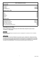
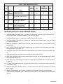
Table 2. Accessories and Tools
ACCESSORIES
Installation kits 1155
Cup Holder 511005000
Cup Holder 511006000
CO
2
Changeover Kit 511035000
GENERIC FLAVOR TABS
Cola 1085
Cherry 1086
Orange 1087
Lemon-Lime 1089
Strawberry 1090
Banana 1091
SERVICE TOOLS
3-gallon Sanitizing Tank 281884000
Socket Spanner, Shank Nut 620711709
Refractometer, 0-30 Scale 511004000
Wrench, Rear Seal Housing 2899
Tool, Drive/Coupler Adjustment Gauge 3810
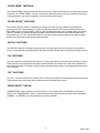
REFRIGERATION SYSTEMS
NOTE: The FCB Dispenser (depending upon the model number) refrigeration system is either
“air-cooled” or “water-cooled”.
“Air-Cooled”
The “air-cooled” FCB Dispenser refrigeration system(s) is equipped with a condenser coil that is cooled by
condenser coil fan(s).
“Water-Cooled”
The “water-cooled” Two-Flavor FCB Dispenser refrigeration system is equipped with a Refrigeration Cooling
Coil Assembly that contains both refrigerant and plain water cooling coils. Circulating cool plain water through
the cooling coil cools the refrigerant also inside the coil. During installation, City cold plain water is connected to
the FCB Dispenser Refrigeration Cooling Coil water inlet line labeled “COOLING WATER IN”. The water drain
line labeled “COOLING WATER OUT” must be routed to and be connected to a permanent drain.

560001279SER 7
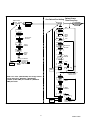
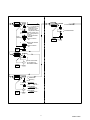
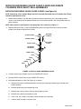
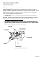
THEORY OF OPERATION
(see applicable Figure 4 or 5)
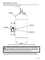
A CO
2
cylinder or a bulk CO
2
supply delivers carbon dioxide (CO
2
) gas to an adjustable primary CO
2
regulator
assembly attached to the cylinder. The primary CO
2
regulator assembly in turn delivers CO
2
gas to an
adjustable secondary CO
2
regulators inside the Unit and also to the soft drink tanks. CO
2
is delivered from the
adjustable secondary CO
2
regulator(s) to the carbonator tank(s) and also to the product-blender tanks inside the
Unit. CO
2
gas pressure pushes syrup out of the soft drink tanks through the syrup sold-out switches, through
adjustable syrup flow regulators, through electrically-operated syrup solenoid valves, and on to the product
blender tanks. At the same time, plain water passes through the water pressure regulator and is pumped into
the carbonator tank(s) by the water pump(s) and is carbonated by CO
2
gas pressure also entering the tank(s).
Carbonated water is pushed by CO
2
gas pressure from the carbonator tank(s), through adjustable carbonated
water flow regulators, through electrically operated carbonated water solenoid valves, and on to the product
blender tanks. Carbonated water and syrup enter the tanks properly proportioned (blended) for desired BRIX of
dispensed product by adjustment of the syrup flow regulators. From product blender tanks, product is pushed by
the CO
2
gas into the freeze cylinders. The beater in each freeze cylinder is driven by an electric motor. Scraper
blades, attached to the beaters, scrapes product from the cylinder walls as product enters the freeze cylinders
and is frozen. Transparent faceplate, attached to the front of each freeze cylinder, includes a self-closing
dispensing valve and a spring-loaded relief valve that protects freeze cylinder from accidental over pressure.
The relief valve is also used to bleed CO
2
gas pressure from the freeze cylinder to atmosphere when filling the
cylinder with product. Electronic sensing on each freeze cylinder motor provides a means of adjusting viscosity
(consistency) of the dispensed product to suit customer preference.
DEFROST SYSTEMS
The Units are equipped with both manual and automatic hot-gas defrost systems. The automatic defrost system
may be programmed into the Unit to occur up to nine different times a day with a minimum of two hours
between defrost time settings or the system may be completely turned off.
MANUAL DEFROST SYSTEM
Two-Flavor FCB Dispenser.
The Manual hot-gas defrost system may be activated at any time by pressing the ‘‘MANUAL DEFROST’’ switch
on the control panel located located behind the front access door on the Unit. The refrigeration compressor will
operate for a short time, then both freeze cylinders will go into defrost and defrost for approximately 60
seconds. At the end of the manual defrost cycle, the Unit will return to normal operation. Manual defrost may be
cancelled at any time by pressing the ‘‘CANCEL DEFROST’’ switch.
Four-Flavor FCB Dispenser.
The Manual hot-gas defrost system may be activated at any time by pressing the “MANUAL DEFROST” switch
on the control panel located behind the front access door on the Unit. The refrigeration compressor will operate
for a short time, then both No. 1 and No.11 or No. 2 and No. 22 (depending upon which “MANUAL DEFROST”
switch was pressed) freeze cylinder only will go into defrost and defrost for one minute. At the end of the
manual defrost cycle, Unit will return to normal operation. Manual defrost may be cancelled at any time by
pressing the “CANCEL DEFROST” switch.

560001279SER
8
AUTOMATIC DEFROST SYSTEM
NOTE: The following paragraph describes the Automatic Hot-Gas Defrost system operation for the
Two-Flavor FCB Dispenser No. 1 and No. 2 freeze cylinders. This paragraph also describes the
Automatic Hot-Gas Defrost system operation for the Four-Flavor FCB Dispenser No. 11 and No. 22
freeze cylinders, which is identical to the No. 1 and No. 2 freeze cylinders.
The automatic hot-gas defrost system may be programmed into the Unit to occur up to nine different times a
day with a minimum of two hours between defrost settings. At the start of each automatic defrost cycle,
refrigeration compressor will operate for 30-seconds to pump freon out of the freeze cylinders evaporator coils.
After freon has been pumped out of the freeze cylinders evaporator coils, No. 1 freeze cylinder only will go into
defrost cycle and defrost for approximately 7-minutes, then will return to normal operation. This ends the
automatic defrost cycle of No. 1 freeze cylinder. No. 2 freeze cylinder will defrost 30-minutes after the start of
No. 1 freeze cylinder. The next automatic defrost cycle will occur according to the time programmed into the
Unit. Automatic defrost may be cancelled at any time by pressing the ‘‘CANCEL DEFROST’’ switch.
‘‘SLEEP’’ (SLEEP TIME)
‘‘SLEEP’’ (SLEEP TIME) may be programmed into Unit to allow Unit to go into sleep time (Unit shut down,
freeze cylinders beaters and refrigeration systems not operating). At start of sleep time, refrigeration
compressor will operate for 30-seconds to pump freon out of freeze cylinders evaporator coils, then No. 1 freeze
cylinder will go into defrost and defrost for 60-seconds. After No. 1 freeze cylinder has defrosted, No. 2 freeze
cylinder will go into defrost and defrost for 60-seconds. At end of No. 2 freeze cylinder defrost, Unit will shut
down and go into sleep time.
‘‘WAKE UP’’ (WAKE UP TIME)
‘‘WAKE UP’’ (WAKE UP TIME) may be programmed into the Unit to allow Unit to resume normal operation at a
desired time. When programmed wake up time is reached, an alarm will sound for a short duration, then Unit
will resume normal operation.

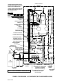
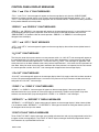
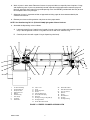
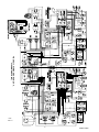
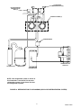
560001279SER 9
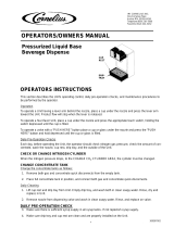
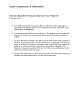
*WATER PRESSURE REGULATOR IS
FACTORY ADJUSTED TO 45–PSI AND
SHOULD NOT BE READJUSTED.
**SYRUP SOLD–OUT SWITCHES ARE
FACTORY ADJUSTED AND SHOULD
NOT BE READJUSTED.
PRODUCT BLENDER
TANK(2)
PRODUCT SAMPLE
VALVE(2)
SYRUP FLOW
REGULATOR(2)
CARBONATOR
TANK
PRODUCT SHUTOFF
VALVE(2)
CARBONATED WATER
VOLUME SAMPLE VALVE
CARBONATED WATER
SOLENOID VALVE(2)
SYRUP SOLENOID
VALVE(2)
PRIMARY CO
2
REGULATOR ASS’Y
CO
2
CYLINDER
CO
2
CHECK
VALVE(3)
SOFT DRINK
TANK(2)
FREEZE
CYLINDER(2)
CARBONATED WATER
FLOW REGULATOR(2)
FREEZE CYLINDER
OVERFLOW TUBE
LIQUID CHECK
VALVE(2)
DOUBLE
LIQUID
CHECK
VALVE
SYRUP SOLD–OUT
FLOAT SWITCH(2)
*WATER PRESSURE
REGULATOR
PLAIN WATER
SOURCE
WATER
PRESSURE
SWITCH
CARBONATOR
WATER PUMP
CO
2
PRESSURE
SWITCH
SECONDARY CO
2
REGULATOR
TO CARBONATOR TANK
(100–PSI GAGE)
SECONDARY CO
2
REGULATORS
TO PRODUCT BLENDER
TANKS (60–PSI GAGE) (2)
**SYRUP SOLD–OUT
SWITCH
CO
2
CHECK
VALVE
LINE LEGEND
CO
2
PLAIN WATER
CARB WATER
SYRUP
PRODUCT
NOTE: THE 3 H.P. FOUR–FLAVOR MODEL IS BASICALLY
TWO 3 H.P. TWO–FLAVOR MODELS JOINED TOGETHER.
FIGURE 4. FLOW DIAGRAM. 3 H.P. DISPENSER (TWO–FLAVOR MODEL SHOWN)

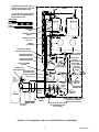
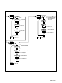
560001279SER
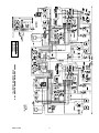
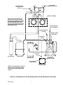
10
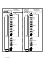
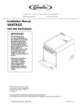
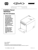
*WATER PRESSURE REGULATOR IS
FACTORY ADJUSTED TO 45-PSI AND
SHOULD NOT BE READJUSTED.
**SYRUP SOLD-OUT SWITCHES ARE
FACTORY ADJUSTED AND SHOULD
NOT BE READJUSTED.
PRODUCT BLENDER
TANK(2)
PRODUCT SAMPLE
VALVE(2)
SYRUP FLOW
REGULATOR(2)
CARBONATOR
TANK
PRODUCT SHUTOFF
VALVE(2)
CARBONATED WATER
VOLUME SAMPLE VALVE
CARBONATED WATER
SOLENOID VALVE(2)
SYRUP SOLENOID
VALVE(2)
PRIMARY CO
2
REGULATOR ASS’Y
CO
2
CYLINDER
CO
2
CHECK
VALVE(3)
SOFT DRINK
TANK(2)
FREEZE
CYLINDER(2)
CARBONATED WATER
FLOW REGULATOR(2)
FREEZE CYLINDER
OVERFLOW TUBE
LIQUID CHECK
VALVE(2)
DOUBLE
LIQUID
CHECK
VALVE
SYRUP SOLD-OUT
FLOAT SWITCH(2)
*WATER PRESSURE
REGULATOR
SHUTOFF
VALVE
PLAIN WATER
SOURCE
WATER
PRESSURE
SWITCH
CARBONATOR
WATER PUMP
CO
2
PRESSURE
SWITCH
SECONDARY CO
2
REGULATOR
TO CARBONATOR TANK
(100-PSI GAGE)
SECONDARY CO
2
REGULATORS
TO PRODUCT BLENDER
TANKS (60–PSI GAGE) (2)
**SYRUP SOLD-OUT
SWITCH
CO
2
CHECK
VALVE
LINE LEGEND
CO
2
PLAIN WATER
CARB WATER
SYRUP
PRODUCT
FIGURE 5. FLOW DIAGRAM (2 AND 3 H.P. OVERCOUNTER OC2 DISPENSER)

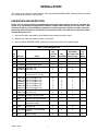
560001279SER 11
INSTALLATION
This section covers unpacking and inspection, installing LOOSE-SHIPPED PARTS, selecting location, installing
Unit, preparing for operation, and operation.
UNPACKING AND INSPECTION
NOTE: The Unit was thoroughly inspected before leaving the factory and the carrier has accepted and
signed for it. Any damage or irregularities should be noted at time of delivery (or not later than 15 days
from date of delivery) and immediately reported to the delivering carrier. Request a written inspection
report from Claims Inspector to substantiate any necessary claim. File claim with the delivering carrier,
not with IMI Cornelius Inc.
1. After Unit has been unpacked, remove shipping tape and other packing material.
2. Remove Unit sides, top and back panels as instructed.
3. Unpack LOOSE-SHIPPED PARTS. Make sure all items are present and in good condition.
Table 3. Loose-Shipped Parts
Item
No. Part No. Name
Qty.
2–fl Floor
Model
Qty.
OC2 Model
Qty.
OC2 Model
(Air Cooled Top
Condensing)
Qty.
4–FL
Model
1 178025100 Tapered Gasket, White 5 4 4 7
2 325216000 Cleaning Brush 1 1 1 1
3 311304000 Tapered Gasket, Black 1 1 1 1
4 620708530
620708529
Cup Rest, 2 FL
Cup Rest, 4 FL
1
X
1
X
1
X
X
1
5 325282000 Thread Cutting Screw, Hx
Hd.;No. 8 by 1/2-in. long
X 2 2 X
6 620051268
620051269
620052090
620052091
620051266
620051297
Drip Tray Support, LH
Drip Tray Support, RH
Drip Tray Support, LH
Drip Tray Support, RH
Drip Tray Support, LH
Drip Tray Support, RH
X
X
1
1
X
X
1
1
X
X
X
X
X
X
1
1
X
X
X
X
X
X
1
1
7 620046231
620517149
Drip Tray, 2 FL
Drip Tray, 4 FL
1
X
1
X
1
X
X
1
8 326002000 Kit, Drip Tray Drain Hose 1 1 X 1
9 2899 Wrench, Rear Seal Housing 1 1 X 1
10 3810 Tool, Drive/Coupler
Adjustment Gauge
1 1 X 1
11 3184 Leveling Leg X 4 X X
12 325018000 Caster Kit, 4-inch diameter
Casters
1 X X 1
13 3247 Spacer, White X 2 X X

560001279SER
12
Table 3. Loose-Shipped Parts (Cont’d)
Item
No. Part No. Name
Qty.
2–fl Floor
Model
Qty.
OC2 Model
Qty.
OC2 Model
(Air Cooled Top
Condensing)
Qty.
4–FL
Model
14 3221
560003645
Front Access Panel
Front Access Panel
X
X
1
X
X
1
X
X
15 3108 Thread Cutting Screw, Phil
Pan Hd; No. 10 by 32 by 1-in.
long
X 2 X X
16 319941000 Thread Rolling Screw, Hex
Washer Hd; No. 8-32 by
3/8-in. Long
4 2 X 4
17 313802000 Snap Bushing, 875 Electric
(used in the top panel if
installing a Merchandiser)
1 1 X 1
18 560001561 Bolt, 3/8–16 X X 4 X
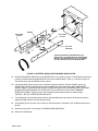
IDENTIFICATION OF LOOSE-SHIPPED PARTS
1. TAPERED GASKETS, WHITE (item 1) are used to seal connections when connecting Unit product inlet
lines to product tanks and connecting Unit CO
2
inlet line to CO
2
source.
2. CLEANING BRUSH (item 2) is used to clean faceplate relief valves passages.
3. TAPERED GASKET, BLACK (item 3) is used to seal connection when connecting plain water source line to
the Unit plain water inlet.
4. WRENCH, REAR SEAL HOUSING (item 9) used to remove the drive shaft/seal assembly from inside the
freeze cylinder.
5. TOOL, DRIVE/COUPLER ADJUSTMENT GAUGE (item 10) is used for servicing the beater motor drive
shaft/seal assembly (see Figure 13).
6. CASTER KIT (item 12) to be installed on the Floor Model Unit as instructed in Instructions provided in the
Kit.
7. LEVELING LEGS (item 11) to be installed on the Overcounter (OC2) Unit base.
8. DRIP TRAY SUPPORTS (item 6) to be installed on front of the Unit and secured with applicable THREAD
ROLLING SCREWS (item 16).
9. DRIP TRAY (item 7) to be installed on the drip tray supports, then CUP REST (item 4) is to be installed in
the drip tray.
10. KIT, DRIP TRAY DRAIN HOSE (item 8) is to be installed on the Unit as instructed. Installation instructions
are included in the Kit.
11. WRENCH REAR SEAL HOUSING (item 9) is used to remove the drive shaft/seal assembly from inside the
freeze cylinder.
12. FRONT ACCESS PANEL (item 14) to be installed on the Overcounter (OC2) Unit and secured with
THREAD CUTTING SCREWS (item 5), SPACERS, WHITE (item 13), and THREAD CUTTING SCREWS
(item 15).

560001279SER 13
SELECTING LOCATION
CAUTION: This Unit is intended for indoor installation only. Do not install this Unit in an
outdoor environment which would expose it to the outside elements.
IMPORTANT: Unit operating ambient temperature MUST NOT EXCEED 100° F. Operating ambient in
excess of 100° F will automatically void the factory warranty and will eventually result in Unit failure.
Several means are available to achieve proper ambient temperature and air circulation around the Unit
which are wall air intake grilles and ceiling exhaust fans, air conditioning, etc. Consult local codes.
Locate Unit so the following requirements are satisfied.
1. Close to a plain water inlet supply line with a minimum pressure of 12-psig.
NOTE: “AIR-COOLED FCB DISPENSER
The “air-cooled” FCB Dispenser refrigeration system is equipped with a condenser coil that is cooled
by condenser coil fan(s). Circulating air, required to cool the refrigeration system’s condenser coil, is
drawn in through the grille on front and exhausted out through the sides and back of Unit. Restricting
air circulation through the Unit will decrease its cooling efficiency.
2. A properly grounded 208–230 VAC, 60Hz single-phase electrical circuit with a 30 Amp minimum-rated
disconnect switch (not provided) fused at 30 Amps (slow-blow) or circuit connected through an equivalent
HACR circuit breaker must be available to the Unit (2 FL). 4 FL units require a 50 Amp minimum–rated
disconnect switch (not provided) fused at 50 Amps (slow blow) or circuit connected through an equivalent
HACR circuit breaker must be available to the Unit. ALL WIRING MUST CONFORM TO NATIONAL AND
LOCAL CODES. MAKE SURE UNIT IS PROPERLY GROUNDED.
CAUTION: Do not place or store anything on top of the Unit.
3. When installing the Unit, do not allow obstruction to block grille on front which will block off air intake to
inside of THE Unit. If installation dictates only one side or the back being unobstructed, allow 18-inches
clearance between the Unit and the obstruction. If both sides or one side and the back are unobstructed,
allow 12-inches clearance. If both sides and the back are unobstructed, allow 6-inches clearance. A
minimum of 12-inches must be provided above the Unit for service and maintenance.
INSTALLING UNIT
INSTALLING APPLICABLE CASTER KIT OR LEVELING LEGS
Floor Model 3 H.P. Unit
Install CASTER KIT, 4-INCH (item 12) on four corners of the Unit base.
Overcounter (OC2) Model 2 and 3 H.P. Units
Very carefully, tilt Unit up and install four LEVELING LEGS (item 11) in four corners of the Unit base.

560001279SER
14
INSTALLING DRIP TRAY SUPPORTS
Overcounter (OC2) Model 2 and 3 H.P. Units
1. Install DRIP TRAY SUPPORT, LEFT and DRIP TRAY SUPPORT, RIGHT (item 6) on front of the Unit and
secure with THREAD CUTTING SCREWS (item 5).
2. Place DRIP TRAY (item 7) on drip tray supports.
3. Place CUP REST (item 4) in drip tray.
Floor Model 3 H.P. Unit
1. Install DRIP TRAY SUPPORTS (item 6) on front of the Unit and secure with THREAD ROLLING SCREWS
(item 16).
2. Place DRIP TRAY (item 7) on drip tray supports.
3. Place CUP REST (item 4) in drip tray
INSTALLING DRIP TRAY DRAIN KIT
1. Install DRIP TRAY DRAIN HOSE KIT (item 8) on Unit as instructed in Installation Instructions provided with
the Kit.
NOTE: Drip tray drain hose may be routed to a waste container, but is not recommended due to
sanitation and cleaning problems. Connection of drain hose to a permanent drain is most highly
recommended.
2. Route drip tray drain hose to and connect to permanent drain.
3. Place CUP REST (item 4) in drip tray.
PLACING UNIT IN OPERATING LOCATION
1. Place Unit in operating location meeting requirements of SELECTING LOCATION.
2. Make sure the Unit is sitting in a level position by using a carpenters level and adjusting the adjustable
casters (Floor Model Unit) or the adjustable leveling legs (Overcounter (OC2) Unit.
Page is loading ...
Page is loading ...
Page is loading ...
Page is loading ...
Page is loading ...
Page is loading ...
Page is loading ...
Page is loading ...
Page is loading ...
Page is loading ...
Page is loading ...
Page is loading ...
Page is loading ...
Page is loading ...
Page is loading ...
Page is loading ...
Page is loading ...
Page is loading ...
Page is loading ...
Page is loading ...
Page is loading ...
Page is loading ...
Page is loading ...
Page is loading ...
Page is loading ...
Page is loading ...
Page is loading ...
Page is loading ...
Page is loading ...
Page is loading ...
Page is loading ...
Page is loading ...
Page is loading ...
Page is loading ...
Page is loading ...
Page is loading ...
Page is loading ...
Page is loading ...
Page is loading ...
Page is loading ...
Page is loading ...
Page is loading ...
Page is loading ...
Page is loading ...
Page is loading ...
Page is loading ...
Page is loading ...
Page is loading ...
Page is loading ...
Page is loading ...
Page is loading ...
Page is loading ...
Page is loading ...
Page is loading ...
Page is loading ...
Page is loading ...
Page is loading ...
Page is loading ...
Page is loading ...
Page is loading ...
Page is loading ...
Page is loading ...
Page is loading ...
Page is loading ...
Page is loading ...
Page is loading ...
Page is loading ...
Page is loading ...
Page is loading ...
Page is loading ...
Page is loading ...
Page is loading ...
-
 1
1
-
 2
2
-
 3
3
-
 4
4
-
 5
5
-
 6
6
-
 7
7
-
 8
8
-
 9
9
-
 10
10
-
 11
11
-
 12
12
-
 13
13
-
 14
14
-
 15
15
-
 16
16
-
 17
17
-
 18
18
-
 19
19
-
 20
20
-
 21
21
-
 22
22
-
 23
23
-
 24
24
-
 25
25
-
 26
26
-
 27
27
-
 28
28
-
 29
29
-
 30
30
-
 31
31
-
 32
32
-
 33
33
-
 34
34
-
 35
35
-
 36
36
-
 37
37
-
 38
38
-
 39
39
-
 40
40
-
 41
41
-
 42
42
-
 43
43
-
 44
44
-
 45
45
-
 46
46
-
 47
47
-
 48
48
-
 49
49
-
 50
50
-
 51
51
-
 52
52
-
 53
53
-
 54
54
-
 55
55
-
 56
56
-
 57
57
-
 58
58
-
 59
59
-
 60
60
-
 61
61
-
 62
62
-
 63
63
-
 64
64
-
 65
65
-
 66
66
-
 67
67
-
 68
68
-
 69
69
-
 70
70
-
 71
71
-
 72
72
-
 73
73
-
 74
74
-
 75
75
-
 76
76
-
 77
77
-
 78
78
-
 79
79
-
 80
80
-
 81
81
-
 82
82
-
 83
83
-
 84
84
-
 85
85
-
 86
86
-
 87
87
-
 88
88
-
 89
89
-
 90
90
-
 91
91
-
 92
92


Cornelius 230 VAC User manual
- Category
- Water dispensers
- Type
- User manual
- This manual is also suitable for
Ask a question and I''ll find the answer in the document
Finding information in a document is now easier with AI
Related papers
-
 Cornelius R-404A REFRIGERANT User manual
-
 Cornelius R-404A User manual
-
 Cornelius 326142000 User manual
-
 Cornelius FCB V4 Unit Operating instructions
-
 Cornelius R-134A User manual
-
 Cornelius VANTAGE POST-MIX DISPENSER User manual
-
 Cornelius R-134A User manual
-
 Cornelius none User manual
-
 Cornelius Venture Installation guide
-
 Cornelius Vantage Pre-Mix Dispenser Installation guide


Other documents
-
 IMI Cornelius, Inc. Vantage User manual
-
MULTIPLEX McCann's Carbonators Installation guide
-
-
-
-
 IMI Cornelius, Inc. VA 13 Installation guide
-
 Eaton Compressor Leaders In Industrial Air Technology --> Owner's manual
-
 IMI Cornelius, Inc. VA13 Installation guide
-
 IMI Cornelius, Inc. Vantage Installation guide
-


