Page is loading ...

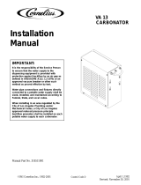
VANTAGE POST-MIX DISPENSER
Service/Maintenance
Manual
IMPORTANT:
TO THE INSTALLER.
It is the responsibility of the
Installer to ensure that the water
supply to the dispensing
equipment is provided with
protection against backflow by an
air gap as defined in ANSI/ASME
A112. 1.2-1979; or an approved
vacuum breaker or other such
method as proved effective by
test.
Water pipe connections and
fixtures directly connected to a
potable water supply shall be
sized, installed, and maintained
according to Federal, State, and
Local laws.
PRINTED IN U.S.A
IMI CORNELIUS INC; 1998Ó
Part No. 312031004
January 26, 1996
Revised: March 3, 1998
Control Code C
THIS DOCUMENT CONTAINS IMPORTANT INFORMATION
This Manual must be read and understood before servicing or maintaining this equipment.

i 312031004
TABLE OF CONTENTS
Page
SAFETY INFORMATION 1. . . . . . . . . . . . . . . . . . . . . . . . . . . . . . . . . . . . . . . . . . . . . . . . . . . .
RECOGNIZE SAFETY INFORMATION 1. . . . . . . . . . . . . . . . . . . . . . . . . . . . . . .
UNDERSTAND SIGNAL WORDS 1. . . . . . . . . . . . . . . . . . . . . . . . . . . . . . . . . . . .
FOLLOW SAFETY INSTRUCTIONS 1. . . . . . . . . . . . . . . . . . . . . . . . . . . . . . . . .
CO2 (CARBON DIOXIDE) WARNING 1. . . . . . . . . . . . . . . . . . . . . . . . . . . . . . . .
SHIPPING, STORING, OR RELOCATING UNIT 1. . . . . . . . . . . . . . . . . . . . . . .
GENERAL INFORMATION 3. . . . . . . . . . . . . . . . . . . . . . . . . . . . . . . . . . . . . . . . . . . . . . . . . .
TO THE USER OF THIS MANUAL 3. . . . . . . . . . . . . . . . . . . . . . . . . . . . . . . . . . . . . . .
CLAIMS INSTRUCTIONS 3. . . . . . . . . . . . . . . . . . . . . . . . . . . . . . . . . . . . . . . . . . . . . .
WARRANTY REFERENCE INFORMATION 3. . . . . . . . . . . . . . . . . . . . . . . . . . . . . . .
DESIGN DATA 3. . . . . . . . . . . . . . . . . . . . . . . . . . . . . . . . . . . . . . . . . . . . . . . . . . . . . . . .
THEORY OF OPERATION 4. . . . . . . . . . . . . . . . . . . . . . . . . . . . . . . . . . . . . . . . . . . . . .
UNIT WITH INTEGRAL (BUILT-IN) COLD CARBONATOR 4. . . . . . . . . . . . . .
UNIT REQUIRING REMOTE CARBONATOR 4. . . . . . . . . . . . . . . . . . . . . . . . .
SERVICE AND MAINTENANCE 7. . . . . . . . . . . . . . . . . . . . . . . . . . . . . . . . . . . . . . . . . . . . .
PREPARING UNIT FOR SHIPPING OR RELOCATING 7. . . . . . . . . . . . . . . . . . . . .
HOOD AND FRONT ACCESS PANEL REMOVAL 7. . . . . . . . . . . . . . . . . . . . . . . . . .
HOOD REMOVAL 7. . . . . . . . . . . . . . . . . . . . . . . . . . . . . . . . . . . . . . . . . . . . . . . . .
FRONT ACCESS PANEL REMOVAL 7. . . . . . . . . . . . . . . . . . . . . . . . . . . . . . . . .
PERIODIC INSPECTION 7. . . . . . . . . . . . . . . . . . . . . . . . . . . . . . . . . . . . . . . . . . . . . . .
ADJUSTMENTS 10. . . . . . . . . . . . . . . . . . . . . . . . . . . . . . . . . . . . . . . . . . . . . . . . . . . . . . .
CO2 REGULATORS ADJUSTMENTS 10. . . . . . . . . . . . . . . . . . . . . . . . . . . . . . . .
ADJUSTING DISPENSING VALVES WATER FLOW RATE 10. . . . . . . . . . . . .
ADJUSTING WATER-TO-SYRUP “RATIO” (BRIX) OF DISPENSED
PRODUCT 11. . . . . . . . . . . . . . . . . . . . . . . . . . . . . . . . . . . . . . . . . . . . . . . . . . . . . . . .
CLEANING AND SANITIZING 12. . . . . . . . . . . . . . . . . . . . . . . . . . . . . . . . . . . . . . . . . . .
DAILY CLEANING OF UNIT 12. . . . . . . . . . . . . . . . . . . . . . . . . . . . . . . . . . . . . . . .
SANITIZING POST-MIX SYRUP SYSTEMS 12. . . . . . . . . . . . . . . . . . . . . . . . . .
CLEANING DROP-IN REFRIGERATION ASSEMBLY CONDENSER COIL 15. . . .
CHECKING ICE WATER BATH 15. . . . . . . . . . . . . . . . . . . . . . . . . . . . . . . . . . . . . . . . . .
CLEANING WATER TANK 16..............................................
CARBONATOR WATER PUMP YEARLY MAINTENANCE OR AFTER
WATER SYSTEM DISRUPTIONS 17. . . . . . . . . . . . . . . . . . . . . . . . . . . . . . . . . . . . . . . .
REMOTE CARBONATOR 17. . . . . . . . . . . . . . . . . . . . . . . . . . . . . . . . . . . . . . . . . .
INTEGRAL (BUILT-IN) CARBONATOR 17. . . . . . . . . . . . . . . . . . . . . . . . . . . . . . .
TROUBLESHOOTING 19. . . . . . . . . . . . . . . . . . . . . . . . . . . . . . . . . . . . . . . . . . . . . . . . . . . . . .
TROUBLESHOOTING UNIT 19. . . . . . . . . . . . . . . . . . . . . . . . . . . . . . . . . . . . . . . . . . . .
WATER-TO-SYRUP ‘‘RATIO’’ TOO LOW OR TOO HIGH. 19. . . . . . . . . . . . . . .
ADJUSTMENT OF DISPENSING VALVE SYRUP FLOW REGULATOR DOES
NOT INCREASE TO DESIRED WATER-TO-SYRUP ‘‘RATIO’’ 19. . . . . . . . . . .
ADJUSTMENT OF DISPENSING VALVE SYRUP REGULATOR DOES NOT
DECREASE TO DESIRED WATER-TO-SYRUP ‘‘RATIO’’. 20. . . . . . . . . . . . . .
DISPENSED PRODUCT CARBONATION TOO LOW. 20. . . . . . . . . . . . . . . . . .

ii
312031004
TABLE OF CONTENTS (cont’d)
Page
DISPENSED PRODUCT COMES OUT OF DISPENSING VALVE CLEAR
BUT FOAMS IN CUP OR GLASS. 20. . . . . . . . . . . . . . . . . . . . . . . . . . . . . . . . . . .
DISPENSED PRODUCT PRODUCES FOAM AS IT LEAVES
DISPENSING VALVE. 20. . . . . . . . . . . . . . . . . . . . . . . . . . . . . . . . . . . . . . . . . . . . . .
NO PRODUCT DISPENSED FROM ALL DISPENSING VALVES 21. . . . . . . .
ONLY CARBONATED WATER DISPENSED. 21. . . . . . . . . . . . . . . . . . . . . . . . . .
ONLY SYRUP DISPENSED. 21. . . . . . . . . . . . . . . . . . . . . . . . . . . . . . . . . . . . . . . .
TROUBLESHOOTING REFRIGERATION SYSTEM 21. . . . . . . . . . . . . . . . . . . . . . . .
COMPRESSOR DOES NOT OPERATE. 21. . . . . . . . . . . . . . . . . . . . . . . . . . . . .
COMPRESSOR WILL NOT STOP AFTER SUFFICIENT ICE BANK IS
PRODUCED. 22. . . . . . . . . . . . . . . . . . . . . . . . . . . . . . . . . . . . . . . . . . . . . . . . . . . . .
COMPRESSOR OPERATES CONTINUOUSLY BUT DOES NOT FORM
SUFFICIENT ICE BANK. 22. . . . . . . . . . . . . . . . . . . . . . . . . . . . . . . . . . . . . . . . . . .
CONDENSER FAN MOTOR NOT OPERATING. 22. . . . . . . . . . . . . . . . . . . . . . .
AGITATOR MOTOR NOT OPERATING. 22. . . . . . . . . . . . . . . . . . . . . . . . . . . . . .
WARRANTY 23. . . . . . . . . . . . . . . . . . . . . . . . . . . . . . . . . . . . . . . . . . . . . . . . . . . . . . . . . . . . . .
LIST OF FIGURES
FIGURE 1. VANTAGE POST--MIX DISPENSER (FIVE-FLAVOR UNIT SHOWN) 4
FIGURE 2. PLUMBING DIAGRAM (FIVE-FLAVOR UNIT WITH INTEGRAL
CARBONATOR SHOWN) 5. . . . . . . . . . . . . . . . . . . . . . . . . . . . . . . . . . . . . . . . . . . . . . .
FIGURE 3. PLUMBING DIAGRAM (FIVE-FLAVOR UNIT W/INTEGRAL CARB AND
ONE NON-CARB
DRINK SHOWN) 5. . . . . . . . . . . . . . . . . . . . . . . . . . . . . . . . . . . . . . . . . . . . . . . . . . . . . . .
FIGURE 4. PLUMBING DIAGRAM (FOUR-FLAVOR UNIT REQUIRING
REMOTE CARBONATOR) 6. . . . . . . . . . . . . . . . . . . . . . . . . . . . . . . . . . . . . . . . . . . . . .
FIGURE 5. PLUMBING DIAGRAM (FIVE-FLAVOR UNIT REQUIRING
REMOTE CARBONATOR) 6. . . . . . . . . . . . . . . . . . . . . . . . . . . . . . . . . . . . . . . . . . . . . .
FIGURE 6. PARTS IDENTIFICATION (FIVE-FLAVOR UNIT WITH INTEGRAL
CARBONATOR SHOWN) 8. . . . . . . . . . . . . . . . . . . . . . . . . . . . . . . . . . . . . . . . . . . . . . .
FIGURE 7. PARTS IDENTIFICATION (FIVE-FLAVOR UNIT REQUIRING REMOTE
CARBONATOR SHOWN) 9. . . . . . . . . . . . . . . . . . . . . . . . . . . . . . . . . . . . . . . . . . . . . . .
FIGURE 8. UF-1 DISPENSING VALVE 11. . . . . . . . . . . . . . . . . . . . . . . . . . . . . . . . . . .
FIGURE 9. WIRING DIAGRAM 18. . . . . . . . . . . . . . . . . . . . . . . . . . . . . . . . . . . . . . . . . .
LIST OF TABLES
TABLE 1. DESIGN DATA 3. . . . . . . . . . . . . . . . . . . . . . . . . . . . . . . . . . . . . . . . . . . . . . .

1 312031004
SAFETY INFORMATION
Recognize Safety Information
This is the safety-alert symbol. When you see this
symbol on our machine or in this manual, be alert to
the potentially of personal injury.
Follow recommended precautions and safe operating
practices.
DANGER
Understand Signal Words
A signal word - DANGER, WARNING, OR CAUTION
is used with the safety-alert symbol. DANGER identi-
fies the most serious hazards.
Safety signs with signal word DANGER or WARNING
are typically near specific hazards.
WARNING
General precautions are listed on CAUTION safety
signs. CAUTION also calls attention to safety mes-
sages in this manual.
CAUTION
Follow Safety Instructions
Carefully read all safety messages in this manual and on your machine safety signs. Keep safety signs in
good condition. Replace missing or damaged safety signs. Learn how to operate the machine and how to
use the controls properly. Do not let anyone operate the machine without instructions. Keep your machine in
proper working condition. Unauthorized modifications to the machine may impair function and/or safety and
affect the machine life.
CO
2
(Carbon Dioxide) Warning
CO
2
Displaces Oxygen. Strict Attention must be observed in the prevention of CO
2
(carbon dioxide)
gas leaks in the entire CO
2
and soft drink system. If a CO
2
gas leak is suspected, particularly in a
small area, immediately ventilate the contaminated area before attempting to repair the leak. Person-
nel exposed to high concentration of CO
2
gas will experience tremors which are followed rapidly by
loss of consciousness and suffocation.
CAUTION: Before shipping, storing, or relocating this Unit, the syrup systems must be sanitized and
all sanitizing solution must be purged from the syrup systems. All water must also be purged from
the plain and carbonated water systems. A freezing ambient temperature will cause residual water
remaining inside the Unit to freeze resulting in damage to internal components of the Unit.
Shipping, Storing, Or Relocating Unit


3
1
2
0
3
1
0
0
4
2
THIS PAGE LEFT BLANK INTENTIONALLY

3
3
1
2
0
3
1
0
0
4
GENERAL INFORMATION
TO THE USER OF THIS MANUAL
This is a Service and Maintenance Manual for the four and five-flavor Vantage Post-Mix Dispensers with integral
(built-in) cold carbonators (see figure 2 or 3) or the four and five-flavor Dispensers requiring connection to re-
mote carbonators (see figures 4 or 5).These Dispensers will hereafter be referred to as Units. Retain this manu-
al as part of your equipment.
This Unit must be installed and serviced by a qualified Service Person. This Unit contains no User serviceable
parts.
CLAIMS INSTRUCTIONS
Claims: In the event of shortage, notify the carrier as well as IMI Cornelius immediately. In the event of dam-
age, notify the carrier. IMI Cornelius is not responsible for damage occurring in transit, but will gladly
render assistance necessary to pursue your claim. Merchandise must be inspected for concealed dam-
age within 15 days of receipt.
WARRANTY REFERENCE INFORMATION
Warranty Registration Date
(to be filled out by customer)
Unit Part Number:
Serial Number:
Install Date:
Local Authorized
Service Center:
DESIGN DATA
Table 1. Design Data
Part Number See Unit nameplate
Dimensions:
Height 18-1/2 inches
Width 15-inches
Depth 26-inches
Maximum Plain Water Pressure (Integral Carbonator Units Only) 45-psi (see NOTE)
Maximum Carbonator CO
2
Pressure (Integral Carbonator Units Only) 60-psi
Voltage/Amps See Unit nameplate
Operating Temperature 40° F to 100° F
NOTE: The plain water source water pressure must not exceed 45-psi. If water pressure exceeds
45-psi, a water pressure regulator must be used to regulate the water pressure.

3
1
2
0
3
1
0
0
4
4
FIGURE 1. VANTAGE POST--MIX DISPENSER (FIVE-FLAVOR UNIT SHOWN)
THEORY OF OPERATION
UNIT WITH INTEGRAL (BUILT-IN) COLD CARBONATOR
(see applicable Figure 2 or 3)
A CO
2
supply delivers carbon dioxide (CO
2
) gas through adjustable CO
2
gas regulators to applicable syrup
tanks or bag-in-box syrup pumps and also to a built-in cold carbonator located inside the Unit. Plain water is
pumped into the carbonated water tank by a water pump and is carbonated by regulated CO
2
gas pressure also
entering the tank. When a dispensing valve is opened, CO
2
gas pressure exerted upon the applicable syrup
tank or bag-in-box syrup pump pushes syrup from the syrup supply, through the Unit cooling coils, and on to the
dispensing valve. Carbonated water is pushed by CO
2
gas pressure from the carbonated water tank and
passes through the Unit carbonated water cooling coils and on to the dispensing valves. Syrup and carbonated
water meet simultaneously at the dispensing valve resulting in a carbonated drink being dispensed. On one
Unit, a non-carbonated (still) drink is dispensed from No. 5 Dispensing valve in the same manner as the carbon-
ated drink except plain water is substituted for carbonated water.
The carbonated water tank is replenished when the carbonated water level inside the tank drops, which in turn
automatically starts the carbonator water pump. When the carbonated water level inside the tank has been re-
plenished, the carbonated water pump will stop.
UNIT REQUIRING REMOTE CARBONATOR
(see applicable Figure 4 or 5)
A CO
2
supply delivers carbon dioxide (CO
2
) gas through adjustable CO
2
gas regulators to applicable syrup
tanks or bag-in-box syrup pumps and also to a remote carbonator that provides carbonated water to the Unit.
Plain water is pumped into the remote carbonator carbonated water tank by a water pump and is carbonated by
regulated CO
2
gas pressure also entering the tank. When a dispensing valve is opened, CO
2
gas pressure ex-
erted upon the applicable syrup tank or bag-in-box syrup pump pushes syrup from the syrup supply, through the
Unit cooling coils, and on to the dispensing valve. Carbonated water is pushed by CO
2
gas pressure from the
remote carbonator carbonated water tank and passes through the Unit carbonated water cooling coils and on to
the dispensing valves. Syrup and carbonated water meet simultaneously at the dispensing valve resulting in a
carbonated drink being dispensed.
The remote carbonator carbonated water tank is replenished when the carbonated water level inside the tank
drops, which in turn automatically starts the carbonator water pump. When the carbonated water level inside the
tank has been replenished, the carbonated water pump will stop.

5
3
1
2
0
3
1
0
0
4
CO
2
IN
60 PSI
CO
2
IN
CARBONATOR
WATER IN
45 PSI MAX
PUMP AND
MOTOR
WATER
COIL
SYRUP INLET
SYRUP
COIL (5)
CARB WATER
MANIFOLD
DISPENSING
VALVE (5)
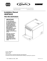
FIGURE 2. PLUMBING DIAGRAM (FIVE-FLAVOR UNIT WITH INTEGRAL CARBONATOR SHOWN)
WATER IN
45 PSI MAX
CO
2
IN
60 PSI
CO
2
IN
CARBONATOR
PUMP AND
MOTOR
WATER
COIL
SYRUP INLET
SYRUP
COIL (5)
CARB WATER
MANIFOLD
DISPENSING
VALVE (5)
NON-CARBONATED
(STILL DRINK)
TEE FITTING
(NOT PROVIDED)
FIGURE 3. PLUMBING DIAGRAM (FIVE-FLAVOR UNIT W/INTEGRAL CARB AND ONE NON-CARB
DRINK SHOWN)

3
1
2
0
3
1
0
0
4
6
CARB WATER
INLET
CARB WATER
INLET
SYRUP
INLET
CARB WATER
COOLING COIL
CARB WATER
COOLING COIL
CARB WATER
MANIFOLD
SYRUP
COOLING COIL (4)
DISPENSING
VALVE (4)
1
2
3
4
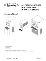
FIGURE 4. PLUMBING DIAGRAM (FOUR-FLAVOR UNIT REQUIRING REMOTE CARBONATOR)
CARB WATER
INLET
CARB WATER
INLET
SYRUP
INLET
CARB WATER
COOLING COIL
CARB WATER
COOLING COIL
CARB WATER
MANIFOLD
SYRUP
COOLING COIL (5)
DISPENSING
VALVE (5)
CARB/PLAIN
WATER INLET
PLAIN WATER
COOLING COIL
1
2
3
4
5
FIGURE 5. PLUMBING DIAGRAM (FIVE-FLAVOR UNIT REQUIRING REMOTE CARBONATOR)

7
3
1
2
0
3
1
0
0
4
SERVICE AND MAINTENANCE
This section describes the service and maintenance procedures to be performed on the Unit.
IMPORTANT: Only qualified Service Personnel should service the internal components or electrical
wiring.
DANGER: To avoid possible fatal electrical shock or serious injury to the operator, it
is required that a GFCI (ground fault circuit interrupt) be installed in the electrical circuit for
the domestic Units. It is required that an ELCB (earth leakage circuit breaker) be installed in
the electrical circuit for the export Units.
WARNING: Disconnect electrical power from the Unit to prevent personal injury before
attempting any internal maintenance. Only qualified personnel should service the internal
components or electrical wiring.
PREPARING UNIT FOR SHIPPING OR RELOCATING
CAUTION: This Unit is intended for indoor installation only. Do not install this Unit in an
outdoor environment which would expose it to the outside elements.
CAUTION: Before shipping, storing, or relocating this Unit, the syrup systems must be
sanitized and all sanitizing solution must be purged from the syrup systems. All water must
also be purged from the plain and carbonated water systems. A freezing ambient
environment will cause residual water in the Unit to freeze resulting in damage to internal
components.
HOOD AND FRONT ACCESS PANEL REMOVAL
(see applicable Figure 6 or 7)
HOOD REMOVAL
CAUTION: Do not place or store anything on top of the Unit.
Remove screw securing hood, then lift hood straight up off the Unit.
IMPORTANT: Circulating air, required to cool the refrigeration assembly condenser coil, is drawn in
through grille on top of the hood and is exhausted out through grille on back of the lower housing
assembly.
FRONT ACCESS PANEL REMOVAL
Remove two screws securing the front access panel, then remove the panel.
PERIODIC INSPECTION
1. Clean the drop-in refrigeration assembly condenser coil every 30-days as instructed. Cleaning the
condenser coil should be performed by a qualified Service Person. DO NOT place objects on top of the
hood or on back side of the Unit. Restricting circulating air in and out of the Unit will cause the refrigeration
system to overheat.

8312031004
HOOD RETAINING
SCREW
HOOD
FRONT ACCESS
PANEL
FRONT ACCESS
PANEL RETAINING
SCREW (2)
DROP-IN
REFRIGERATION ASS’Y
DOUBLE LIQUID
CHECK VALVE
WATER TANK
OVERFLOW TUBE
115/24 VAC
TRANSFORMER
CONDENSER
COIL
AGITATOR
MOTOR
CONTROL
BOX
CARBONATOR
WATER TANK
CO
2
CHECK VALVE
DISPENSING
VALVE (5)
SYRUP INLET
TUBE (5)
WATER TANK
DRAIN HOSE
DRIP TRAY
CUP REST
INSULATION PAD
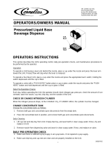
FIGURE 6. PARTS IDENTIFICATION (FIVE-FLAVOR UNIT WITH INTEGRAL CARBONATOR SHOWN)

9
3
1
2
0
3
1
0
0
4
HOOD RETAINING
SCREW
HOOD
FRONT ACCESS
PANEL
FRONT ACCESS
PANEL RETAINING
SCREW (2)
DROP-IN
REFRIGERATION ASS’Y
WATER TANK
OVERFLOW TUBE
115/24 VAC
TRANSFORMER
CONDENSER
COIL
AGITATOR
MOTOR
CONTROL
BOX
DISPENSING
VALVE (5)
SYRUP INLET
TUBE (5)
WATER TANK
DRAIN HOSE
DRIP TRAY
CUP REST
CARB WATER INLET TUBE
FIGURE 7. PARTS IDENTIFICATION (FIVE-FLAVOR UNIT REQUIRING REMOTE CARBONATOR SHOWN)

10312031004
2. Check the dispensing valves for dripping that indicates leakage and repair as necessary.
ADJUSTMENTS
CO
2
REGULATORS ADJUSTMENTS
WARNING: CO
2
displaces oxygen. Strict attention must be observed in the prevention of
CO
2
(carbon dioxide) gas leaks in the entire CO
2
and soft drink system. If a CO
2
gas leak is
suspected, particularly in a small area, immediately ventilate the contaminated area before
attempting to repair the leak. Personnel exposed to high concentration of CO
2
gas will experience
tremors which are followed rapidly by loss of consciousness and suffocation.
NOTE: To readjust CO
2
regulator to a lower setting, loosen adjusting screw lock nut, then turn screw to
the left (counterclockwise) until pressure gage reads 5 psi lower than new setting will be. Turn the
adjusting screw to the right (clockwise) until the gage registers new setting, then tighten the lock nut.
Adjusting Carbonator CO
2
Regulator.
UNIT WITH INTEGRAL (BUILT-IN) COLD CARBONATOR
Adjust CO
2
regulator for the Unit integral (built-in) carbonator at 60-psi maximum.
UNIT REQUIRING REMOTE CARBONATOR
Adjust CO
2
regulator for the remote carbonator to CO
2
pressure specified in manual provided with the
carbonator.
Adjusting Syrup Source CO
2
Regulator.
SUGAR SYRUP TANKS CO
2
REGULATOR
Adjust syrup tanks CO
2
regulator to a minimum of 45-psi.
SYRUP PUMPS (BAG-IN-BOX SYSTEM)
Adjust the syrup pumps CO
2
regulator to 70-psi. DO NOT EXCEED MAXIMUM CO
2
PRESSURE SPECIFIED
ON THE SYRUP PUMPS.
ADJUSTING DISPENSING VALVES WATER FLOW RATE
(see Figure 8)
1. Remove cover from the dispensing valve by lifting the front cover up 1/4 inch and pulling forward.
2. Install syrup diversion tube assembly on the dispensing valve by pushing rubber end of the syrup diversion
tube onto the syrup outlet of the inner nozzle.
3. Measure the water flow rate by dispensing water into a graduated cup for a set period of time.
NOTE: Adjusting screw stops are built into the valve to prevent leakage when the screws are adjusted
too far clockwise. Stop adjusting clockwise when turning resistance increases. Turn the screw
counterclockwise 1--1/2 turns after the stop are contacted.
4. Turn the water flow regulator adjusting screw to the left (counterclockwise) to decrease the water flow rate
or turn the adjusting screw to the right (clockwise) to increase the water flow rate, then recheck the flow
rate. Adjustments should be no more than 1/4 turn at a time.
5. Remove syrup diversion tube from the dispensing valve, then install cover on the dispensing valve.

1
1
3
1
2
0
3
1
0
0
4
WATER FLOW
REGULATOR
SYRUP FLOW
REGULATOR
INNER NOZZLE
NOZZLE
SYRUP DIVERSION
TUBE
RATIO CUP
Counterclockwise
to Decrease
Clockwise
to Increase
FIGURE 8. UF-1 DISPENSING VALVE
ADJUSTING WATER-TO-SYRUP “RATIO” (BRIX) OF DISPENSED PRODUCT
(see Figure 8)
NOTE: Make sure the dispensing valve water flow rate is as desired before adjusting the valve for
Water-to-Syrup ‘‘Ratio’’ (Brix) of the dispensed product.
Adjust Water--to--Syrup “Ratio” (Brix) of the dispensed product by using ratio cup (P/N 311100000) and syrup
diversion tube assembly (P/N 319540000) as follows:
1. Remove cover from the dispensing valve by lifting front cover up 1/4 inch and pulling forward.
2. Install syrup diversion tube assembly on the dispensing valve by pushing the rubber end of the syrup
diversion tube onto the syrup outlet of the inner nozzle.
Notice: Refer to syrup manufacturer’s recommendations on syrup package for water-to-syrup ratio.
3. Dispense enough to fill syrup diversion tube with syrup.
4. Hold large chamber of the ratio cup under the dispensing valve nozzle. Place free end of the syrup
diversion tube into the syrup chamber marked for the proper ratio. Dispense approximately 6 ounces of
water into the ratio cup. Water and syrup levels should be even in cup.
Note: Adjusting screw stops are built into the valve to prevent leakage when the screws are adjusted
clockwise too much. Stop adjusting clockwise when turning resistance increases. Turn the screw
counterclockwise 1--1/2 turns after the stop are contacted.
5. Adjusting Syrup Flow Regulator -- If water and syrup levels are uneven in the ratio cup, adjust by
turning the dispensing valve syrup flow regulator adjusting screw labeled SYRUP as follows.

12312031004
A. For less syrup, turn the adjusting screw counterclockwise no more than 1/4 turn at a time.
B. For more syrup, turn the adjusting screw clockwise no more than 1/4 turn at a time.
6. Repeat water-to-syrup ratio test and adjust syrup flow regulator as many times as necessary until proper
ratio of dispensed drink is achieved.
7. Remove syrup diversion tube assembly from dispensing valve.
8. Install dispensing valve front cover.
CLEANING AND SANITIZING
DAILY CLEANING OF UNIT
1. Remove cup rest from the drip tray.
2. Wash drip tray in place on the Unit, then rinse drip tray with hot water allowing water to drain out through
the drain hose.
3. Wash cup rest, then rinse the cup rest with clean water. Install cup rest in the drip tray.
4. Clean all external surfaces of the Unit with a sponge. Rinse out the sponge with clean water, then wring
excess water out of the sponge and wipe off all external surfaces on the Unit. Wipe Unit dry with a clean
soft cloth. DO NOT USE ABRASIVE CLEANERS.
5. Remove nozzle and syrup diffusers from the dispensing valves. Place nozzles and syrup diffusers in
sanitizing solution.
6. Wash the nozzles and syrup diffusers in sanitizing solution, then rinse them with potable water.
7. Re-install nozzles and syrup diffusers back on the dispensing valves.
SANITIZING POST-MIX SYRUP SYSTEMS
IMPORTANT: Only qualified Service Personnel should perform sanitizing procedure on the post-mix
syrup systems.
The post-mix syrup systems should be sanitized every 90-days using a non-scented household liquid bleach
containing a 5.25 % sodium hypochlorite concentration. Proceed as follows to sanitize the post-mix syrup
systems.
1. Disconnect syrup supplies from syrup systems.
2. Rinse quick disconnects (syrup tanks systems) or bag-in-box connectors (syrup bag-in-box systems) in
warm potable water.
STEP 1. WASH SYRUP SYSTEMS
3. Using a clean syrup tank (syrup tank system) or a five-gallon container (bag-in-box system), prepare a full
tank or container of liquid dishwasher detergent by using 70_ F (21_ C) to 100_ F (38_ C) potable water
and 0.5 oz. (15 ml) of liquid dishwasher detergent to one gallon of potable water. Stir detergent solution to
thoroughly mix the solution.
4. Syrup Tank Systems.
A. Observe and note CO
2
pressure setting on the syrup tanks CO
2
regulator, then re-adjust CO
2
regulator to 60 to 80-psi. Pressurize syrup tank containing detergent solution to 60 to 80-psi.
B. Connect detergent solution tank, pressurized at 60 to 80-psi, into one of the syrup systems.

1
3
3
1
2
0
3
1
0
0
4
Bag-in Box Syrup Systems.
C. Install bag valves, cut from empty bag-in-box syrup containers, on ends of syrup containers syrup
outlet tubes connectors.
D. Place all syrup outlet tubes, with bag valves on their ends, in container containing detergent solution.
5. Flush the syrup system and dispensing valve as follows:
A. Place waste container under applicable dispensing valve.
B. Activate the dispensing valve for one minute to purge all syrup and flush out the syrup system.
C. Continue to activate the dispensing valve in cycles (“ON” for 15-seconds, “OFF”, then “ON” for
15-seconds). Repeat “ON” and “OFF” cycles for 15-cycles.
6. Connect detergent solution to the remaining syrup systems and flush syrup out of the syrup systems as
instructed in step 5 preceding.
7. Remove detergent solution source from the syrup system.
STEP 2. FLUSH SYRUP SYSTEMS
8. Syrup Tank Systems.
Connect syrup tank containing potable water, pressurized at 60 to 80-psi, into one of the syrup systems.
Bag-in-Box Syrup System.
Fill five-gallon container with potable water, then place all bag-in-box syrup containers syrup outlet tubes in
container containing potable water.
9. Flush detergent solution out of the syrup system and dispensing valve as follows:
A. Place waste container under applicable dispensing valve.
B. Activate the dispensing valve for one minute to purge all detergent solution and flush out the syrup
system.
C. Continue to activate the dispensing valve in cycles (“ON” for 15-seconds, “OFF”, then “ON” for
15-seconds). Repeat “ON” and “OFF” cycles for 15-cycles.
10. Connect potable water source to the remaining syrup systems and flush detergent solution out of the syrup
systems as instructed in step 9 preceding.
11. Remove potable water source from the syrup system.
STEP 3. SANITIZE SYRUP SYSTEMS
12. Using a clean syrup tank (syrup tanks system) or a five-gallon container (bag-in-box system), prepare
sanitizing solution using 70_ F (21_ C) to100_ F (38_ C) potable water and 0.5 oz. (15 ml) of non-scented
household liquid bleach that contains a 5.25 % sodium hypochlorite concentration to one gallon of potable
water. This mixture must not exceed 200 PPM of chlorine. Stir sanitizing solution to thoroughly mix.
13. Syrup Tank Systems.
Connect sanitizing solution tank, pressurized at 60 to 80-psi, into one of the syrup systems.
Bag-in-Box Syrup System.
Place all bag-in-box syrup containers syrup outlet tubes in container containing sanitizing solution.
14. Sanitize the syrup system and dispensing valve as follows:
A. Place waste container under applicable dispensing valve.

14312031004
B. Activate the dispensing valve for one minute to purge all water from and install sanitizing solution in
the syrup system and dispensing valve.
C. Continue to activate the dispensing valve in cycles (“ON” for 15-seconds, “OFF”, then “ON” for
15-seconds). Repeat “ON” and “OFF” cycles for 15-cycles.
15. Repeat steps13 and 14 to flush water out of and install sanitizing solution in the remaining syrup systems
and dispensing valves.
16. Remove sanitizing solution source from the syrup system.
17. Allow sanitizing solution to remain in the syrup systems for not less than 10 or no more than 15-minutes
(max.) contact time.
STEP 4. WATER FLUSH SYRUP SYSTEMS
WARNING: Flush sanitizing solution from the syrup systems as instructed. Residual
sanitizing solution left in the syrup systems could create a health hazard.
18. Fill syrup tank (syrup tank system) or a five-gallon container (bag-in-box system) with potable water.
19. Syrup Tank Systems.
Connect syrup tank containing potable water, pressurized at 60 to 80-psi, into one of the syrup systems.
Bag-in-Box Syrup System.
Place all bag-in-box syrup containers syrup outlet tubes in container containing potable water.
20. Flush sanitizing solution from the syrup system and the dispensing valve as follows:
A. Place waste container under applicable dispensing valve.
B. Activate the dispensing valve for one minute to purge all sanitizing solution out of the syrup system
and the dispensing valve.
C. Continue to activate the dispensing valve in cycles (“ON” for 15-seconds, “OFF”, then “ON” for
15-seconds). Repeat “ON” and “OFF” cycles for 15-cycles.
21. Repeat steps 19 and 20 preceding to purge sanitizing solution out of the remaining syrup systems and
dispensing valves.
22. Remove potable water source from the syrup system.
STEP 5. PURGE WATER OUT OF SYRUP SYSTEMS (RESTORE OPERATION)
23. Syrup Tank Systems.
A. Noting syrup tanks CO
2
regulator pressure setting observed in step 4 preceding, readjust CO
2
regulator to the observed pressure setting,
B. Connect tanks containing syrup into syrup systems.
Bag-in-Box Syrup System.
C. Remove all bag valves from bag-in-box syrup containers outlet tubes connectors.
D. Connect bag-in-box syrup containers into the syrup systems.
24. Place waste container under dispensing valves. Dispense from all dispensing valves to permit syrup to
purge all potable water from the syrup systems and the dispensing valves. Continue to dispense from the
dispensing valves until only syrup is dispensed from the syrup systems and valves.
WARNING: To avoid possible personal injury or property damage, do not attempt to
remove the syrup tank cover until CO
2
pressure has been released from the tank.

1
5
3
1
2
0
3
1
0
0
4
25. Dispose of waste sanitizing solution in a sanitary sewer, not in a storm drain, then thoroughly rinse the
inside and the outside of the container that was used for sanitizing solution to remove all sanitizing solution
residue.
CLEANING DROP-IN REFRIGERATION ASSEMBLY CONDENSER COIL
(see applicable Figure 6 or 7)
CAUTION: The refrigeration assembly condenser coil must be cleaned every 30-days.
Excessive accumulation of dust, lint, and grease on the condenser coil will restrict air flow
through the coil and cause the refrigeration system to overheat. Operating the refrigeration
system in an overheated condition will eventually lead to compressor failure and will automatically
void the factory warranty.
Clean the drop-in refrigeration assembly coil as follows:
1. Unplug Unit power cord from the electrical outlet.
2. Remove screw securing the hood, then lift the hood straight up to remove.
3. Vacuum or use a soft brush to clean the condenser coil. If available, use low-pressure compressed air.
4. Clean dust and dirt from around top of the drop-in refrigeration assembly.
5. Install hood on the Unit and secure with screw.
6. Plug Unit power cord into electrical outlet. The refrigeration system will start after a 2-minute time delay.
CHECKING ICE WATER BATH
(see Figure 6)
A ‘‘gurgle’’ heard from the Unit indicates water level in the water tank is low and more water should be added for
maximum cooling. Before adding more water, check the ice water bath for cleanliness and check the water tank
coils for excessive mineral deposit build-up.
1. Unplug Unit power cord from electrical outlet.
2. Remove screw securing the hood, then lift the hood straight up to remove.
3. Lift insulation pad covering front section of the water tank for visual inspection of the ice water bath and
the ice bank.
4. Using a flashlight, inspect the ice water bath and ice bank for cleanliness. The ice water bath should be
clear and the ice bank should be free of foreign particles.
5. If cleaning of the water tank is necessary, refer to CLEANING WATER TANK in this section.
6. Fill the water tank with clean water until water begins to run out of the overflow tube into the drip tray. USE
LOW-MINERAL-CONTENT WATER WHERE A LOCAL WATER PROBLEM EXISTS.
7. Lower the insulation pad into proper position on top of the water tank.
8. Install Unit hood and secure with screw.
9. Plug Unit power cord into electrical outlet. The refrigeration system will start after a 2-minute time delay.

16312031004
CLEANING WATER TANK
(see Figure 6)
1. Unplug the Unit power cord from electrical outlet.
2. Close shutoff valve in plain water source line connected to the Unit.
3. Remove two screws securing the Unit front access panel, then remove the panel.
4. Extend the water tank drain hose (located on front of Unit) to a waste container or floor drain. Remove plug
from end of the drain hose and allow the water tank to drain.
5. Remove screw securing the hood, then lift the hood straight up to remove from the Unit.
6. Unit With Integral (Built-In) Cold Carbonator. (see Figures 2 and 6)
A. Disconnect plain water source line from Unit double liquid check valve assembly inlet.
B. Disconnect carbonator water pump plain water outlet line from carbonated water tank plain water inlet
line.
7. Unplug the drop-in refrigeration assembly and electric dispensing valve power cords at connectors on front
of the Unit.
CAUTION: The ice bank around the drop-in refrigeration assembly evaporator coils must be
completely melted before attempting to lift the drop-in refrigeration assembly up and out of
the Unit lower cabinet assembly. Attempting to lift the drop-in refrigeration assembly and
ice bank together up out of the Unit lower housing assembly may cause damage to the evaporator
coils.
CAUTION: Never use an ice pick or other instrument to remove ice from the drop-in
refrigeration assembly evaporator coils. Such practice can result in a punctured
refrigeration circuit.
8. Allow the ice bank around the drop-in refrigeration assembly evaporator coils to completely melt. Hot water
may be used to speed up the melting process.
9. Very carefully, lift the drop-in refrigeration assembly up and out of the Unit lower housing assembly..
10. Use a fiber brush and carefully clean mineral deposit build-up from the agitator motor shaft and the ice
bank sensing bulb.
11. Wash inside of the water tank and the drop-in refrigeration assembly evaporator coils, then rinse with clean
water.
12. Install plug in end of the water tank drain hose.
13. Very carefully, install drop-in refrigeration assembly in Unit lower housing assembly by reversing the
removal procedure.
14. Unit With Integral (Built-In) Cold Carbonator. (see Figures 2 and 6)
A. Connect carbonator water pump plain water outlet line to carbonated water tank plain water inlet line.
B. Connect plain water source line to Unit double liquid check valve assembly inlet.
15. Fill the water tank with clean water until water runs out of the water tank overflow hose. USE
LOW-MINERAL-CONTENT WATER WHERE A LOCAL WATER PROBLEM EXISTS.
16. Plug Unit power cord into electrical outlet. The refrigeration system will start after a 2-minute time delay.
/