Page is loading ...

IMPORTANT:
TO THE INSTALLER.
It is the responsibility of the Installer to
ensure that the water supply to the
dispensing equipment is provided with
protection against backflow by an air gap
as defined in ANSI/ASME A112. 1.2-1979; or
an approved vacuum breaker or other such
method as proved effective by test.
Water pipe connections and fixtures
directly connected to a potable water
supply shall be sized, installed, and
maintained according to Federal, State,
and Local laws.
PRINTED IN U.S.A
IMI CORNELIUS INC; 1982-95Ó
VA13 CARBONATOR
Installation Manual
Part No. 318511-000
April 1, 1982
Revised: April 21, 1995
THIS DOCUMENT CONTAINS IMPORTANT INFORMATION
This Manual must be read and understood before installing or operating this equipment

i 318511-000
TABLE OF CONTENTS
Page
GENERAL INFORMATION 1. . . . . . . . . . . . . . . . . . . . . . . . . . . . . . . . . . . . . . . . . . . . . . . . . .
GENERAL DESCRIPTION 1. . . . . . . . . . . . . . . . . . . . . . . . . . . . . . . . . . . . . . . . . . . . . .
UNIT DESCRIPTION 1. . . . . . . . . . . . . . . . . . . . . . . . . . . . . . . . . . . . . . . . . . . . . . . . . . .
THEORY OF OPERATION 2. . . . . . . . . . . . . . . . . . . . . . . . . . . . . . . . . . . . . . . . . . . . . .
INSTALLATION 3. . . . . . . . . . . . . . . . . . . . . . . . . . . . . . . . . . . . . . . . . . . . . . . . . . . . . . . . . . .
UNPACKING AND INSPECTION 3. . . . . . . . . . . . . . . . . . . . . . . . . . . . . . . . . . . . . . . .
IDENTIFICATION OF LOOSE-SHIPPED PARTS 3. . . . . . . . . . . . . . . . . . . . . . . . . .
SELECTING LOCATION 3. . . . . . . . . . . . . . . . . . . . . . . . . . . . . . . . . . . . . . . . . . . . . . . .
INSTALLING THE UNIT 4. . . . . . . . . . . . . . . . . . . . . . . . . . . . . . . . . . . . . . . . . . . . . . . .
PLACING UNIT IN OPERATING LOCATION 4. . . . . . . . . . . . . . . . . . . . . . . . . .
CONNECTING PLAIN WATER INLET LINE TO UNIT 4. . . . . . . . . . . . . . . . . .
CONNECTING CO2 INLET LINE TO UNIT 5. . . . . . . . . . . . . . . . . . . . . . . . . . .
CONNECTING CARBONATED WATER OUTLET LINE TO UNIT 5. . . . . . . .
PERMANENT ELECTRICAL POWER CONNECTION TO DOMESTIC UNIT IF
REQUIRED BY LOCAL CODES 5. . . . . . . . . . . . . . . . . . . . . . . . . . . . . . . . . . . . . . . .
PREPARATION FOR OPERATION 6. . . . . . . . . . . . . . . . . . . . . . . . . . . . . . . . . . . . . .
ADJUSTING CARBONATOR CO2 REGULATOR AND TURN PLAIN WATER
INLET LINE ON 6. . . . . . . . . . . . . . . . . . . . . . . . . . . . . . . . . . . . . . . . . . . . . . . . . . .
UNIT OPERATION 6. . . . . . . . . . . . . . . . . . . . . . . . . . . . . . . . . . . . . . . . . . . . . . . . . . . . .
OPERATOR’S INSTRUCTIONS 9. . . . . . . . . . . . . . . . . . . . . . . . . . . . . . . . . . . . . . . . . . . . .
PERIODIC INSPECTION 9. . . . . . . . . . . . . . . . . . . . . . . . . . . . . . . . . . . . . . . . . . . . . . .
CHECKING CO2 SUPPLY 9. . . . . . . . . . . . . . . . . . . . . . . . . . . . . . . . . . . . . . . . . .
PERIODIC CHECKING FOR CO2 AND WATER LEAKS 9. . . . . . . . . . . . . . . .
ADJUSTMENTS 9. . . . . . . . . . . . . . . . . . . . . . . . . . . . . . . . . . . . . . . . . . . . . . . . . . . . . . .
ADJUSTING CARBONATOR TANK LIQUID LEVELS 9. . . . . . . . . . . . . . . . . .
WATER PUMP YEARLY MAINTENANCE (OR AFTER WATER SYSTEM
DISRUPTION) 9. . . . . . . . . . . . . . . . . . . . . . . . . . . . . . . . . . . . . . . . . . . . . . . . . . . . . . . .
UNIT MODEL NO. 416411 AND 496411 9. . . . . . . . . . . . . . . . . . . . . . . . . . . . .
UNIT MODEL NO. 1621 9. . . . . . . . . . . . . . . . . . . . . . . . . . . . . . . . . . . . . . . . . . .
PERIODIC CLEANING 10. . . . . . . . . . . . . . . . . . . . . . . . . . . . . . . . . . . . . . . . . . . . . . . . .
SERVICE AND MAINTENANCE 11. . . . . . . . . . . . . . . . . . . . . . . . . . . . . . . . . . . . . . . . . . . . .
PREPARING UNIT FOR SHIPPING, STORING OR RELOCATING 11. . . . . . . . . . .
PERIODIC CLEANING 11. . . . . . . . . . . . . . . . . . . . . . . . . . . . . . . . . . . . . . . . . . . . . . . . .
ADJUSTMENTS 11. . . . . . . . . . . . . . . . . . . . . . . . . . . . . . . . . . . . . . . . . . . . . . . . . . . . . . .
ADJUSTING CARBONATOR TANK LIQUID LEVELS 12. . . . . . . . . . . . . . . . . .
WATER PUMP YEARLY MAINTENANCE (OR AFTER WATER SYSTEM
DISRUPTIONS) 13. . . . . . . . . . . . . . . . . . . . . . . . . . . . . . . . . . . . . . . . . . . . . . . . . . . . . . .
SERVICING WATER PUMP WATER INLET STRAINER SCREEN 13. . . . . . .
SERVICING DOUBLE-CHECK VALVE 13. . . . . . . . . . . . . . . . . . . . . . . . . . . . . . .
THE VENTED DUAL-CHECK VALVE ASSEMBLY 15. . . . . . . . . . . . . . . . . . . . .
REPAIR AND REPLACEMENT 15. . . . . . . . . . . . . . . . . . . . . . . . . . . . . . . . . . . . . . . . . .
LEVEL CONTROL SWITCH(S) 15. . . . . . . . . . . . . . . . . . . . . . . . . . . . . . . . . . . . .
SAFETY THERMOSTAT 16. . . . . . . . . . . . . . . . . . . . . . . . . . . . . . . . . . . . . . . . . . .
WATER PUMP 16. . . . . . . . . . . . . . . . . . . . . . . . . . . . . . . . . . . . . . . . . . . . . . . . . . .

ii318511-000
TABLE OF CONTENTS (cont’d)
Page
WATER PUMP MOTOR 17. . . . . . . . . . . . . . . . . . . . . . . . . . . . . . . . . . . . . . . . . . . .
VENTED DUAL--CHECK VALVE ASSEMBLY 17. . . . . . . . . . . . . . . . . . . . . . . . .
TROUBLESHOOTING 23. . . . . . . . . . . . . . . . . . . . . . . . . . . . . . . . . . . . . . . . . . . . . . . . . . . . .
WATER PUMP MOTOR WILL NOT OPERATE. 23. . . . . . . . . . . . . . . . . . . . . . .
WATER PUMP MOTOR WILL NOT SHUT OFF. 23. . . . . . . . . . . . . . . . . . . . . . .
ERRATIC CYCLING OF CARBONATOR. 23. . . . . . . . . . . . . . . . . . . . . . . . . . . . .
WATER PUMP MOTOR OPERATES BUT WATER PUMP DOES NOT
PUMP WATER. 24. . . . . . . . . . . . . . . . . . . . . . . . . . . . . . . . . . . . . . . . . . . . . . . . . . .
WATER PUMP CAPACITY TOO LOW. 24. . . . . . . . . . . . . . . . . . . . . . . . . . . . . . .
WARRANTY 25. . . . . . . . . . . . . . . . . . . . . . . . . . . . . . . . . . . . . . . . . . . . . . . . . . . . . . . . . . . . . .
LIST OF FIGHURES
FIGURE 1. VA13 CARBONATOR ASS’Y 2. . . . . . . . . . . . . . . . . . . . . . . . . . . . . . . . . .
FIGURE 2. CARBONATOR CONNECTIONS 4. . . . . . . . . . . . . . . . . . . . . . . . . . . . . .
FIGURE 3. LEVEL CONTROL SWITCHES 12. . . . . . . . . . . . . . . . . . . . . . . . . . . . . . . .
FIGURE 4. CARBONATOR ASSEMBLY COMPONENTS 14. . . . . . . . . . . . . . . . . . .
FIGURE 5. WATER STRAINER SCREEN AND DOUBLE-CHECK VALVE 18. . . . .
FIGURE 6. CHECK VALVE ASSEMBLY 18. . . . . . . . . . . . . . . . . . . . . . . . . . . . . . . . . .
FIGURE 7. VENTED DUAL- CHECK VALVE LOCATION 20. . . . . . . . . . . . . . . . . . . .
FIGURE 8. BARBED VENTED POSITION 20. . . . . . . . . . . . . . . . . . . . . . . . . . . . . . . .
FIGURE 9. WIRING DIAGRAM 21. . . . . . . . . . . . . . . . . . . . . . . . . . . . . . . . . . . . . . . . . .
FIGURE 10. INSTRUCTIONS FOR CRIMPING TUBE CLAMPS 22. . . . . . . . . . . . .
LIST OF TABLES
TABLE 1. DESIGN DATA 1. . . . . . . . . . . . . . . . . . . . . . . . . . . . . . . . . . . . . . . . . . . . . . .
TABLE 2. LOOSE-SHIPPED PARTS 3. . . . . . . . . . . . . . . . . . . . . . . . . . . . . . . . . . . . .

1 318511-000
GENERAL INFORMATION
IMPORTANT: To the user of this manual - This manual is a guide for installing, operating, and
maintaining this equipment. Refer to table of contents for page location of detailed information
pertaining to questions that arise during installation, operation, service and maintenance, or
troubleshooting this equipment.
GENERAL DESCRIPTION
This section gives the description, theory of operation, and design data for the cabinetized VA13 Remote Carbo-
nator (hereafter referred to as a Unit).
UNIT DESCRIPTION
The carbonator is a compact Unit that may be installed in a remote location from where its carbonated water
outlet is to be connected to post-mix dispenser or system. The purpose of the Unit is to mix plain water and car-
bon dioxide (CO
2
) gas which results in and provides carbonated water for a post-mix dispenser or system. The
Unit consists basically of a water pump, motor and a carbonated water tank. The water pump has a double--
check valve (Unit Model No. 416411 and 496411) or a Vented Dual-Check Valve (Unit Model No. 1621) on its
outlet to prevent carbonated water from back flowing into the city water system. The Vented--Dual Check Valve
vents water and possibly CO
2
gas out of a vent port on failure of the Primary Check Valves. Should such vent-
ing occur, the Primary Check Valve should be replaced. The Unit CO
2
inlet has a single check valve to prevent
carbonated water back flow into CO
2
regulator.
The only connections required for operation are connections to a plain water source, a regulated CO
2
source,
an electrical source with proper electrical requirements, and carbonated water connection to a dispenser or
post-mix system.
CAUTION: Before shipping, storing, or relocating, all water must be purged from
carbonator. A freezing ambient environment will cause residual water remaining inside
carbonator to freeze resulting in damage to internal components.
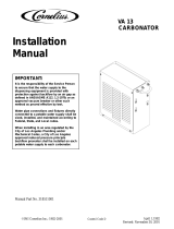
Table 1. Design Data
Model Numbers
Domestic Unit 416411
Domestic Unit 1621
W/Venting Check Valve
Export Unit 496411
Overall Dimensions:
Width 6-3/8 inches
Height 15 inches
Depth 14 inches
Weight:
Dry 28-3/4 pounds
Shipping 30-1/4 pounds
Ambient Operating Temperature 40° F to 100° F

2318511-000
Table 1. Design Data (cont’d)
Electrical Requirements:
Domestic Unit:
Current Draw 6.8 Amps
Operating Voltage 115VAC, 60 Hz
Export Unit
Current Draw 3.3 Amps
Operating Voltage 220/230VAC, 50/60 Hz
FIGURE 1. VA13 CARBONATOR ASS’Y
THEORY OF OPERATION
A CO
2
cylinder delivers carbon dioxide (CO
2
) gas through an adjustable CO
2
regulator to the carbonator tank.
At the same time, plain water is pumped into carbonator tank by water pump and is carbonated by CO
2
also
entering tank. Carbonated water enters tank until weight of water in tank forces tank and balance control mech-
anism down to activate level control switches. Activating level control switches disrupts electrical power to and
stops water pump motor. As carbonated water is dispensed from tank, tank becomes lighter allowing tank and
balance control mechanism to rise which again activates level control switches. Activating level control switches
restores electrical power to water pump motor allowing carbonator tank to be replenished.

3 318511-000
INSTALLATION
This section covers unpacking and inspection, identification of LOOSE-SHIPPED PARTS, selecting location,
installing Unit, preparing Unit for operation, and Unit operation.
UNPACKING AND INSPECTION
NOTE: This Unit was thoroughly inspected before leaving the factory and the carrier has accepted and
signed for it. Any damage or irregularities should be noted at time of delivery (or not later than 15 days
from date of delivery) and immediately reported to the delivering carrier. Request a written inspection
report from Claims Inspector to substantiate any necessary claim. File claim with the delivering carrier,
not with IMI Cornelius Inc.
1. After Unit has been unpacked, remove shipping tape and other packing material. Check for obvious dam-
age and follow procedure in preceding NOTE if damage is evident.
2. Unpack LOOSE-SHIPPED PARTS. Make sure items are present and in good condition.
Table 2. Loose-Shipped Parts
Item No. Part No. Name
41-6411 1621
Qty.
1 1178025-100 Tapered Gasket, White 2 2
2 311304 Tapered Gasket, Black 1 1
IDENTIFICATION OF LOOSE-SHIPPED PARTS
1. TAPERED GASKETS, WHITE (item 1) are used to seal connections when connecting CO
2
inlet and
carbonated water outlet lines to Unit.
2. TAPERED GASKET, BLACK (item 2) is used to seal connection when connecting plain water inlet line to
Unit.
SELECTING LOCATION
Locate the Unit so the following requirements are satisfied.
1. Locate the Unit in a cool area close to a properly grounded electrical outlet with proper electrical require-
ments fused at 15-amps (slow-blow). No other electrical appliance should be connected to this circuit. ALL
WIRING MUST CONFORM TO NATIONAL AND LOCAL CODES. MAKE SURE ELECTRICAL OUTLET
IS PROPERLY GROUNDED.
2. Locate the Unit close to a plain water source line with requirements as outlined in following CAUTION note.
Plain water inlet line from plain water source line should be 3/8-inch I.D. (minimum) food grade plastic.
3. Locate the Unit close to a permanent drain if installing Unit (P/N1621) which is equipped with a Vented
Dual-Check Valve.
IMPORTANT: To avoid possible back-suction from the drain, locate the vent end above the drain, or as
required by the local plumbing code.
CAUTION: Route the free end of the vent tube to a permanent drain to avoid serious water
damage in event of primary check valve failure.

4318511-000
INSTALLING THE UNIT
IMPORTANT: Before putting carbonator into operation, carbonator cover must be removed and packing
block must be removed from below the water pump motor.
PLACING UNIT IN OPERATING LOCATION
1. Place carbonator in operating location meeting requirements of SELECTING LOCATION. MAKE SURE
CARBONATOR IS SITTING IN LEVEL POSITION FOR PROPER OPERATION.
2. Remove four screws securing cover assembly on Unit, then remove cover.
3. Remove packing block from below the water pump motor.
4. Install cover assembly on Unit and secure with four screws.
5. Unit Model No. 1621.
IMPORTANT: A vented dual-check valve assembly is installed in this carbonator between the water
pump outlet and the water inlet to the carbonator tank as shown in Figure 4. The vented dual-check
valve assembly vents carbonated water, and possibly CO
2
gas out of a vent port upon failure of the
primary check valves. Should such venting occur, the vented dual-check valve assembly must be
replaced.
CAUTION: Route free end of the vented dual-check valve vent tube to a permanent drain to
avoid serious water damage in the event of a check valve failure.
Route free end of the dual-check valve vent tube, protruding out the end of the carbonator cabinet, to a perma-
nent drain. TO AVOID POSSIBLE BACK-SUCTION FROM THE PERMANENT DRAIN, LOCATE THE
CHECK VALVE VENT TUBE ABOVE THE DRAIN, OR AS REQUIRED BY THE LOCAL PLUMBING CODE.
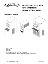
CONNECTING PLAIN WATER INLET LINE
to unit (see Figure 2)
NOTE: IMI Cornelius Inc. recommends that a water shutoff valve and water filter be installed in plain
water inlet line. A Cornelius Water Filter (P/N 313860-000) and Quick Disconnect Set (P/N 313867-000)
are recommended.
CO
2
INLET
POWER CORD
PLAIN WATER INLET
CARB (CARBONATED)
WATER OUTLET
FIGURE 2. CARBONATOR CONNECTIONS

5 318511-000
CAUTION: Check minimum flow rate and maximum pressure of plain water inlet supply
line. MINIMUM FLOW RATE MUST BE AT LEAST 100-GALLONS PER HOUR. If flow rate is
less than 100-gallons per hour, starving of carbonator water pump will occur. Starving will
allow carbonator water pump to overheat causing safety thermostat on pump outlet to disrupt
electrical power to and stop water pump motor. Overheating could occur if plain water inlet
supply line flow rate drops below 100-gallons per hour. WATER PRESSURE MUST BE 10-PSI LESS
THAN THE CO
2
PRESSURE. (Example: operating CO
2
pressure is 80-psi, maximum water pressure
can be no more than 70-psi, etc.) Water over pressure (higher than operating pressure) can cause
carbonator flooding, malfunction, and leakage through carbonator relief valve. If water is
exceeding maximum pressure specifications, a Water Pressure Regulator Kit (P/N 310150-000) or
equivalent must be installed in plain water inlet supply line. If fitting connector is not available,
tap into plain water supply line with a 3/8-flare saddle valve (P/N 315664-000) or equivalent.
1. Make sure food grade flexible plastic 3/8-inch I.D. (minimum) plain water inlet line provides adequate water
flow rate and pressure as outlined in CAUTION note.
Before connecting plain water inlet line to Unit, open water line for a period of time to flush out any metal
shavings resulting from connecting water line to fitting connector or saddle valve.
2. Remove shipping cap from 3/8-inch flare (5/8-18) male fitting on unit labeled WATER INLET.
3. Install TAPERED GASKET (item 2) in plain water inlet line swivel nut, then connect water line to 3/8-flare
male fitting labeled WATER INLET on the Unit.
CONNECTING CO
2
INLET LINE TO UNIT (see Figure 2)
1. Remove shipping cap from 1/4-inch flare (7/16-20) male fitting on Unit labeled CO
2
INLET.
2. Connect CO
2
inlet line from CO
2
regulator to 1/4-inch flare (7/16-20) male fitting on Unit labeled CO
2
INLET. Seal connection with TAPERED GASKET (item 1).
CONNECTING CARBONATED WATER OUTLET LINE TO UNIT (see Figure 2)
WARNING: Under no circumstances should copper tubing, copper fittings, or brass
fittings be used to connect Unit carb (carbonated) water outlet to Post-Mix Dispenser or
system. CO
2
gas contact with copper tubing, copper fittings, or brass fittings will cause a
health hazard.
1. Extend length of food grade flexible plastic tubing (carbonated water line) from the Carbonator carbonated
water outlet to the carbonated water inlet of the Post-Mix dispenser or the system.
2. Remove shipping cap from the 1/4-inch flare (7/16-20) male fitting labeled CARB WATER on the
Carbonator.
3. Connect the carbonated water line to the 1/4-inch flare (7/16-20) male fitting labeled CARB WATER on the
Carbonator. Seal connection with TAPERED GASKET (item 1). Connect other end of the carbonated water
line to the carbonated water inlet of the Post-Mix dispenser or the system.
PERMANENT ELECTRICAL POWER CONNECTION TO DOMESTIC UNIT IF REQUIRED BY
LOCAL CODES (see Figure 4 and 9)
1. Remove two screws and remove cabinet cover.
2. Loosen two screws securing motor wiring compartment cover, then remove cover.

6318511-000
3. Disconnect green (ground) electrical wire from under ground terminal connection screw located inside
motor wiring compartment.
4. Disconnect black and white power cord wires inside motor wiring compartment.
5. Remove power cord and strain relief from Unit.
WARNING: The Unit must be electrically grounded to avoid possible fatal electrical shock
or serious injury to the operator. The Unit power cord is equipped with a three-prong plug.
If a three-hole (grounded) electrical outlet is not available, use an approved method to
ground the Unit.
6. Connect 115 VAC, 60 Hz electrical power from disconnect switch (not furnished) fused at 15-amps
(slow-blow) to Unit with No. 16 AWG wire in suitable conduit or BX sheath. Install power source green wire
under ground terminal screw located inside motor wiring compartment (see Figure 9). Connect black power
cord wire with wire nut and white wire under nut on motor terminal. All WIRING MUST CONFORM TO
NATIONAL AND LOCAL ELECTRICAL CODES.
7. Install motor wiring compartment cover and secure the two cover screws.
8. Install cabinet cover and secure with two screws.
PREPARATION FOR OPERATION
ADJUSTING CARBONATOR CO
2
REGULATOR AND TURN PLAIN WATER INLET LINE
ON
CAUTION: Before connecting CO
2
regulator assembly to CO
2
cylinder, turn regulator
adjusting screw to the left (counterclockwise) until all tension is relieved from adjusting
screw spring.
1. Open (counterclockwise) CO
2
cylinder valve slightly to allow lines to slowly fill with gas, then open valve
fully to back-seat valve. (Back-seating valve prevents leakage around valve shaft).
2. Adjust the carbonator CO
2
regulator to a nominal 80-psi.
3. Open one of the Dispenser dispensing valves to exhaust trapped air inside the carbonator tank.
CAUTION: Never operate the carbonator with the plain water inlet line shutoff valve closed.
‘‘Dry running” the water pump will burn out the pump. A pump damaged in this manner is
not covered by warranty.
4. Open the plain water inlet line shutoff valve.
UNIT OPERATION
NOTE: The carbonator tank liquid levels (pump cut-in and cut-out) were adjusted at the factory and
should require no further adjustment. If carbonator tank relief valve opens before the water pump
motor cycles off, adjust carbonator tank liquid levels as instructed in SERVICE AND MAINTENANCE.
WARNING: The Unit must be electrically grounded to avoid possible fatal electrical shock
or serious injury to the operator. The Unit power cord is equipped with a three-prong plug.
If a three-hole (grounded) electrical outlet is not available, use an approved method to
ground the Unit.

7 318511-000
1. Connect electrical power to the Unit. Water pump will start and fill the carbonator tank with carbonated
water. Water pump will stop when carbonator tank is full.
WARNING: CO
2
Displaces Oxygen. Strict Attention must be observed in the prevention of
CO
2
(carbon dioxide) gas leaks in the entire CO
2
and soft drink system. If a CO
2
gas leak is
suspected, particularly in a small area, immediately ventilate the contaminated area before
attempting to repair the leak. Personnel exposed to high concentration of CO
2
gas will experience
tremors which are followed rapidly by loss of consciousness and suffocation.
WARNING: Disconnect electrical power to the carbonator to prevent personal injury
before attempting any internal maintenance. Only qualified personnel should service
internal components or electrical wiring.
2. Check for CO
2
, carbonated water, and plain water leaks and if evident, tighten any loose connections.

318511-000 8
THIS PAGE LEFT BLANK INTENTIONALLY

9 318511-000
OPERATOR’S INSTRUCTIONS
This section covers operator’s cleaning and maintenance responsibilities for the Unit.
WARNING: Disconnect electrical power to the carbonator to prevent personal injury before
attempting any internal maintenance. Only qualified personnel should service internal
components or electrical wiring.
PERIODIC INSPECTION
CHECKING CO
2
SUPPLY
Make sure CO
2
cylinder regulator assembly 1800-psi gage indicator is not in shaded (‘‘change CO
2
cylinder’’)
portion of dial. If so, CO
2
cylinder is almost empty and must be replaced.
PERIODIC CHECKING FOR CO
2
AND WATER LEAKS
Periodically check the Unit for CO
2
and water leaks and if evident, repair as necessary.
ADJUSTMENTS
ADJUSTING CARBONATOR CO
2
REGULATOR
Carbonator CO
2
regulator should be periodically checked for proper pressure setting and if necessary, adjusted
as instructed in SERVICE AND MAINTENANCE.
ADJUSTING CARBONATOR TANK LIQUID LEVELS
The carbonator tank liquid levels (pump cut-in and cut-out) were adjusted at the factory and should require no
further adjustment. If incorrect adjustment is suspected, adjust carbonator tank liquid levels as instructed in
SERVICE AND MAINTENANCE.
WATER PUMP YEARLY MAINTENANCE (OR AFTER WATER SYSTEM
DISRUPTION)
UNIT MODEL NO. 416411 AND 496411 (see Figure 4)
The water pump water strainer screen and double-check valve must be inspected and cleaned at least once a
year under normal circumstances and after any water system disruption (plumbing work, earthquake, etc.).
Inspect and clean the water strainer screen and double-check valve as instructed in SERVICE AND
MAINTENANCE.
UNIT MODEL NO. 1621 (see Figure 4)
The water pump water strainer screen must be inspected and cleaned at least once a year under normal
circumstances and after any water system disruption (plumbing work, earthquake, etc.) as instructed in
SERVICE AND MAINTENANCE.

318511-000 10
IMPORTANT: A vented dual-check valve assembly is installed in this carbonator between the water
pump outlet and the water inlet to the carbonator tank as shown in Figure 4. The vented dual-check
valve assembly vents carbonated water, and possibly CO
2
gas out of a vent port upon failure of the
primary check valves. Should such venting occur, the assembly must be replaced.
PERIODIC CLEANING
Periodic cleaning of unit should be performed as instructed in SERVICE AND MAINTENANCE.

11
318511-000
SERVICE AND MAINTENANCE
This section describes service and maintenance procedures to be performed on the Unit.
WARNING: Disconnect electrical power to the carbonator to prevent personal injury before
attempting any internal maintenance. Only qualified personnel should service the internal
components or electrical wiring.
CAUTION: Never operate the carbonator with plain water inlet line shutoff valve closed.
‘‘Dry running’’ the water pump will burn out the pump. A pump damaged in this manner is
not covered by warranty.
PREPARING UNIT FOR SHIPPING, STORING OR RELOCATING
CAUTION: Before shipping, storing, or relocating, all water must be purged from the
carbonator. A freezing ambient environment will cause residual water remaining inside the
carbonator to freeze resulting in damage to it’s internal components.
1. Disconnect electrical power from Unit.
2. Close the plain water inlet line shutoff valve.
3. Disconnect plain water inlet line from the Unit.
4. Dispense from the Post-Mix Dispenser dispensing valve until all carbonated water has been dispensed
from the carbonated water tank.
5. Shut off CO
2
supply to the Unit, then disconnect CO
2
inlet supply line from the Unit.
6. Connect filtered dry compressed air (50-psi max) to the Unit water inlet. DO NOT USE CO
2
GAS WHICH
COULD CAUSE A HEALTH HAZARD.
7. Dispense from Post-Mix Dispenser dispensing valve until all residual water has been blown from Unit and
lines.
8. Disconnect filtered dry compressed air from Unit water inlet.
9. Disconnect carbonated water outlet line from the Unit.
10. The Unit is now ready for shipping or relocating.
PERIODIC CLEANING
Clean all external surfaces of the Unit with a sponge. Rinse out the sponge with clean water, then wring excess
water out of the sponge and wipe off external surfaces of the Unit. Wipe the Unit dry with a clean soft cloth. DO
NOT USE ABRASIVE CLEANERS.
ADJUSTMENTS
ADJUSTING CARBONATOR CO
2
REGULATOR
NOTE: To readjust the CO
2
regulator to a lower setting, loosen adjusting screw lock nut, then turn the
adjusting screw to the left (counterclockwise) until pressure gage reads 5-psi lower than new setting
will be. Turn the adjusting screw to the right (clockwise) until the gage registers a new setting, then
tighten the lock nut. Adjust the carbonator CO
2
regulator to a nominal 80-psi.

12
318511-000
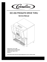
ADJUSTING CARBONATOR TANK LIQUID LEVELS (see Figures 3 and 4)
NOTE: The carbonator tank liquid levels (pump cut-in and cut-out) were adjusted at the factory and
should require no further adjustment. If incorrect adjustment is suspected, check and make necessary
adjustments as follows:
1. Remove screws securing cover assembly on Unit, then remove cover.
2. With carbonator tank full of water and water pump motor cycled off, disconnect electrical power from Unit.
3. Using container graduated in ounces, open dispensing valve and completely drain carbonator tank. Total
carbonated water dispensed should be 40 to 60-ounces.
WARNING: To avoid possible electrical shock which may cause serious injury or death,
make sure electrical power is disconnected from unit before attempting to adjust level
control switches.
4. Under 40-ounces of carbonated water dispensed.
If total amount of carbonated water dispensed is under 40-ounces, loosen screw securing switch adjust-
ment bracket and move bracket up slightly. Moving bracket allows weight of more water in tank to push
tank further down before activating level control switches which shuts off water pump. Tighten screw after
adjustment.
Over 60-ounces of carbonated water dispensed.
If total measurement of carbonated water dispensed is over 60-ounces, loosen screw securing switch
adjustment bracket and move bracket down slightly. Moving bracket down allows weight of less water in
tank to activate level control switches which shuts off water pump motor. Tighten screw after adjustment.
5. Connect electrical power to the Unit and allow carbonator tank to fill with water. After water pump motor
cycles off, disconnect electrical power from the Unit.
6. Repeat steps 3, 4, and 5 preceding until correct switch adjustment is achieved.
7. Connect electrical power to the Unit and allow carbonator tank to fill with water.
8. Using container graduated in ounces, open Post-Mix Dispenser dispensing valve and dispense until pump
motor cycles on, then immediately close dispensing valve. Total volume dispensed (differential) should be 8
to 20-ounces.
9. Install cover assembly on the Unit and secure with screws.
LEVEL CONTROL
SWITCH (2)
SWITCH ADJUSTMENT
BRACKET
SWITCH
ACTUATOR
(2)
TANK BRACKET
FIGURE 3. LEVEL CONTROL SWITCHES

13
318511-000
WATER PUMP YEARLY MAINTENANCE (OR AFTER WATER SYSTEM
DISRUPTIONS)
WARNING: The carbonator water pump water inlet strainer screen and double--check valve
(Unit Model No. 416411 and 496411) must be inspected and serviced at least once a year
under normal circumstances, and after any disruptions (plumbing work, earthquake, etc.)
to the water supply system that might cause turbulent (erratic) flow of water through system. If
system has a Vented Dual-Check Valve (Unit Model No. 1621) clean the carbonator water pump
water inlet strainer screen and flush the system. A carbonator water pump with no screen or a
defective screen in strainer would allow foreign particles to foul the double-check valve. CO
2
gas
could then back flow into the water system and create a health hazard in the water system.
SERVICING WATER PUMP WATER INLET STRAINER SCREEN (see Figures 4 and 5)
1. Disconnect electrical power from Unit.
2. Close plain water inlet line shutoff valve.
3. Note pressure setting on carbonator CO
2
regulator, then loosen lock nut and turn CO
2
regulator adjusting
screw to the left (counterclockwise) until regulator gage reads 0-psi.
4. Remove screws securing the cover assembly on the unit, then remove the cover.
5. Pull up on carbonator tank relief valve to release CO
2
pressure in the tank.
6. Loosen screen retainer, then pull screen retainer and strainer screen from the water pump.
7. Pull strainer screen from screen retainer. Clean any sediment from the screen retainer and water pump
screen retainer port.
8. Inspect the strainer screen for holes, restrictions, corrosion and other damage. Discard damaged strainer
screen.
9. Check O-Ring on the screen retainer. Replace worn or damaged O-Ring (P/N 315349-000).
NOTE: A strainer screen should always be used, otherwise particles could foul the double-check valve.
10. Install good or new strainer screen (P/N 315348-000) in the screen retainer, then screw retainer into water
pump and tighten securely.
11. Service double-check valve (refer to next paragraph, SERVICING DOUBLE-CHECK VALVE).
SERVICING DOUBLE-CHECK VALVE (see Figure 5 and 6)
1. Refer to steps 1 through 5 in SERVICING WATER PUMP WATER INLET STRAINER SCREEN to
prepare the carbonator for servicing it’s double-check valve.
2. Loosen the screw on the pump-to-motor coupling, then turn the water pump for access to the
double-check valve assembly.
3. Disconnect water tank inlet line from the check valve assembly, then remove the check valve assembly
from the elbow in the water pump outlet. Retain the white tapered gasket inside the inlet (female) end of
the double-check valve.

14
318511-000
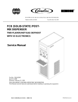
COVER
CHECK VALVE
(CO
2
INLET)
WATER PUMP MOTOR
(ELECTRICAL CONNECTIONS)
CARBONATOR
TANK
RELIEF
VALVE
RETAINING
SCREW (2)
BALANCE CONTROL MECHANISM
LEVEL CONTROL SWITCH (2)
DOUBLE--CHECK VALVE
OR
VENTED DUAL--CHECK
VALVE
SAFETY THERMOSTAT
RETAINING SCREWS (2)
WATER PUMP
FIGURE 4. CARBONATOR ASSEMBLY COMPONENTS
4. Disassemble each check valve as shown in Figure 6.
5. Wipe each part with clean lint-free cloth. Inspect each part, especially the ball for burrs, nicks, corrosion,
deterioration, and other damage. Discard the ball seat and any damaged or suspicious parts and replace
with new parts during reassembly.
6. Reassemble the check valves as shown in Figure 6. ALWAYS INSTALL NEW BALL SEAT (QUAD RING)
P/N 312418-000.
NOTE: Make sure when assembling the check valves together, check valve female end with white ta-
pered gasket inside is on inlet side of the double-check valve assembly.
7. Assemble check valves together. DO NOT OVERTIGHTEN.
8. Make sure white tapered gasket is in place inside the female end of the check valve assembly, then install
the check valve assembly in the elbow in the water pump outlet port.

15
318511-000
9. Connect water tank inlet line to the double check valve assembly outlet. MAKE SURE TO HOLD A
WRENCH ON THE CHECK VALVE “RETAINER HEX NUT” (SEE FIGURE 6) WHEN INSTALLING AND
TIGHTENING THE WATER TANK INLET LINE ON THE CHECK VALVE OUTLET (DO NOT OVER
TIGHTEN).
10. Turn the carbonator CO
2
regulator adjusting screw to the right (clockwise) until gage indicates pressure
setting noted in step 3 of SERVICING WATER PUMP WATER STRAINER SCREEN. Tighten adjusting
screw lock nut.
11. Open shutoff valve in the Unit plain water inlet line.
12. Connect electrical power to the Unit. The water pump will cycle on and fill the carbonator tank. Check for
leaks and tighten any loose connections.
13. Pull up on the carbonator tank relief valve to release trapped air in the tank.
14. Install the cover assembly on the Unit and secure with screws.
THE VENTED DUAL-CHECK VALVE ASSEMBLY
A vented dual-check valve assembly is installed in the carbonator between the water pump outlet and the water
inlet to the carbonator tank as shown in Figure 4. The vented dual-check valve assembly vents carbonated
water, and possibly CO
2
gas out of a vent port upon failure of the primary check valves. Should such venting
occur, the vented dual-check valve assembly must be replaced.
WARNING: Strict attention must be observed in the prevention of CO
2
(carbon dioxide)
gas leaks in the entire CO
2
soft drink system. If a CO
2
gas leak is suspected, particularly in
a small area, immediately ventilate the contaminated area before attempting to repair the
leak. Personnel exposed to high concentration of CO
2
gas will experience tremors which are
followed rapidly by loss of consciousness and suffocation.
REPAIR AND REPLACEMENT
LEVEL CONTROL SWITCH(S) (see Figure 3)
NOTE: If level control switch(s) are determined to be at fault, it will be necessary to test each switch
individually for proper operation and replace switch(s) as necessary.
Removal.
1. Disconnect electrical power from the Unit.
2. Remove screws securing the cover on the Unit, then remove the cover.
3. Tag level control switches electrical wires for identification, then disconnect the electrical wires from the
switches.
4. Remove two screws securing the level control switches, then remove switches from the Unit.
5. Individually check each level control switch for proper operation.
Installation.
1. Install the new switch(s) by reversing the Removal procedure.

16
318511-000
2. Make sure electrical wiring is correct (see Figure 9).
SAFETY THERMOSTAT (see Figure 4 and 9)
IMPORTANT: If necessary to replace the safety thermostat, use only Replacement Safety Thermostat Kit
(P/N 318040-088) with special additional installation instructions included with the Kit.
Removal.
1. Disconnect electrical power from the Unit.
2. Remove screws securing the cover on the Unit, then remove the cover.
3. Loosen two screws securing the wiring compartment cover on pump motor, then remove the cover.
4. Disconnect safety thermostat electrical wire from the electrical wire inside the motor wiring compartment
and terminal on level control switch.
5. Note position of the safety thermostat on the water pump outlet, then remove the thermostat.
6. Disconnect thermostat electrical wire from the motor wiring compartment and level switch, then remove
thermostat from the Unit.
Installation.
1. Install the new safety thermostat by reversing Removal procedure.
2. Make sure electrical wiring is correct (see Figure 9).
WATER PUMP (see Figure 5)
Removal.
1. Disconnect electrical power from the Unit.
2. Close CO
2
cylinder shutoff valve, then close the shutoff valve in the plain water inlet line.
3. Remove screws securing the cover on the Unit, then remove the cover.
4. Pull up on the carbonator tank relief valve to release CO
2
pressure in the tank.
5. Loosen screw on the pump-to-motor coupling enough to turn the pump for access to the double-check
valve assembly.
6. Disconnect the water inlet line from the water pump inlet. Be careful not to lose the black tapered gasket
inside the swivel nut.
7. Disconnect the water tank inlet line from the double-check valve assembly.
8. Remove the double-check valve or vented dual-check valve assembly from the elbow in the water pump
outlet. Be careful not to lose the white tapered gasket inside the double-check valve assembly inlet side.
9. Note position of the safety thermostat on the water pump outlet, then remove the thermostat.
10. Remove elbows from the water pump inlet and outlet.

17
318511-000
11. Loosen screw on the water pump-to-motor coupling enough to remove the pump from the motor.
Installation.
1. Install the new water pump by reversing the Removal procedure and use the following instructions:
A. Make sure pipe thread sealing compound is used on the elbow threads before installing them in inlet
and outlet of the new water pump.
B. Make sure drive tang on the water pump and slot in pump motor shaft are properly lubricated and
aligned when installing the pump on the motor.
C. Make sure applicable tapered gasket is installed at each connection.
2. Open CO
2
cylinder valve, then open plain water inlet line shutoff valve.
3. Connect electrical power to the Unit.
4. Check the Unit for leaks during operation. Tighten any loose connections.
5. Install the cover assembly on the Unit and secure with four screws.
WATER PUMP MOTOR (see Figure 5)
Removal.
1. Disconnect electrical power from the Unit.
2. Remove screws securing the cover on the Unit, then remove the cover.
3. Loosen screw on the water pump-to-motor coupling enough to remove the pump from the motor, then
remove the pump.
4. Loosen the two motor access plate screws, then remove the access plate.
5. Tag the electrical wires for identification, then disconnect the wires from the terminals on the motor.
6. Remove the four screws securing the motor, then remove the motor from inside the Unit.
Installation.
1. Install the new water pump motor by reversing the Removal procedure.
2. Make sure the tang on the water pump and the slot in the pump motor shaft are properly lubricated and
aligned when installing the pump on the motor.
3. Make sure all wiring is correct (see Figure 9).
VENTED DUAL-CHECK VALVE ASSEMBLY (see Figures 4, 7, and 8)
Removal.
1. Disconnect electrical power from the Unit.
2. Close CO
2
cylinder shutoff valve, and shutoff valve in the plain water inlet line.
/