Page is loading ...

FCB (SOLID-STATE) POST-
MIX DISPENSER
TWO-FLAVOR/HOT-GAS DEFROST
WITH V3 ELECTRONICS
Service Manual
IMI CORNELIUS INC g One Cornelius Place g Anoka, MN 55303-6234
Telephone (800) 238-3600 Facsimile (612) 422-3246
PRINTED IN U.S.A
IMI CORNELIUS INC; 1989–92
Part No. 326142000
April 24, 1989
Revised: February 10, 1992
THIS DOCUMENT CONTAINS IMPORTANT INFORMATION
This Manual must be read and understood before installing or operating this equipment

i
326142000
TABLE OF CONTENTS
Page
GENERAL INFORMATION 1. . . . . . . . . . . . . . . . . . . . . . . . . . . . . . . . . . . . . . . . . . . . . . . . . .
GENERAL DESCRIPTION 1. . . . . . . . . . . . . . . . . . . . . . . . . . . . . . . . . . . . . . . . . . . . . .
UNIT DESCRIPTION 1. . . . . . . . . . . . . . . . . . . . . . . . . . . . . . . . . . . . . . . . . . . . . . . . . . .
THEORY OF OPERATION 2. . . . . . . . . . . . . . . . . . . . . . . . . . . . . . . . . . . . . . . . . . . . . .
DEFROST SYSTEMS 2. . . . . . . . . . . . . . . . . . . . . . . . . . . . . . . . . . . . . . . . . . . . . . . . . .
MANUAL DEFROST SYSTEM 3. . . . . . . . . . . . . . . . . . . . . . . . . . . . . . . . . . . . . .
AUTOMATIC DEFROST SYSTEM 3. . . . . . . . . . . . . . . . . . . . . . . . . . . . . . . . . . .
‘‘SLEEP’’ (SLEEP TIME) 3. . . . . . . . . . . . . . . . . . . . . . . . . . . . . . . . . . . . . . . . . . . . . . . .
‘‘WAKE UP’’ (WAKE UP TIME) 3. . . . . . . . . . . . . . . . . . . . . . . . . . . . . . . . . . . . . . . . . . .
INSTALLATION 5. . . . . . . . . . . . . . . . . . . . . . . . . . . . . . . . . . . . . . . . . . . . . . . . . . . . . . . . . . . .
UNPACKING AND INSPECTION 5. . . . . . . . . . . . . . . . . . . . . . . . . . . . . . . . . . . . . . . .
IDENTIFICATION OF LOOSE-SHIPPED PARTS 5. . . . . . . . . . . . . . . . . . . . . . . . . . .
INSTALLING BEATERS (ITEM 11) AND SCRAPER BLADES (ITEM 12) 6. . . . .
ELECTRICAL POWER REQUIREMENTS 6. . . . . . . . . . . . . . . . . . . . . . . . . . . . . . . . .
DOMESTIC UNIT 6. . . . . . . . . . . . . . . . . . . . . . . . . . . . . . . . . . . . . . . . . . . . . . . . . .
EXPORT UNIT 8. . . . . . . . . . . . . . . . . . . . . . . . . . . . . . . . . . . . . . . . . . . . . . . . . . . .
SELECTING LOCATION 8. . . . . . . . . . . . . . . . . . . . . . . . . . . . . . . . . . . . . . . . . . . . . . . .
INSTALLING UNIT 9. . . . . . . . . . . . . . . . . . . . . . . . . . . . . . . . . . . . . . . . . . . . . . . . . . . . .
INSTALLING DRIP TRAY SUPPORTS, DRIP TRAY, AND CUP REST 9. . . .
INSTALLING DRIP TRAY DRAIN KIT (ITEM 14) 9. . . . . . . . . . . . . . . . . . . . . . .
INSTALLING PRIMARY CO2 REGULATOR ASSEMBLY ON CO2
CYLINDER 9. . . . . . . . . . . . . . . . . . . . . . . . . . . . . . . . . . . . . . . . . . . . . . . . . . . . . . .
CONNECTING SOFT DRINK TANKS CO2 LINES TO PRIMARY CO2
REGULATOR ASSEMBLY 10. . . . . . . . . . . . . . . . . . . . . . . . . . . . . . . . . . . . . . . . . .
PREPARING UNIT SYRUP INLET LINES FOR CONNECTION TO SOFT
DRINK TANKS 10. . . . . . . . . . . . . . . . . . . . . . . . . . . . . . . . . . . . . . . . . . . . . . . . . . . .
CONNECTING PLAIN WATER INLET SUPPLY LINE TO UNIT 10. . . . . . . . . .
CONNECTING ELECTRICAL POWER CIRCUIT TO UNIT 11. . . . . . . . . . . . .
PREPARATION FOR OPERATION 11. . . . . . . . . . . . . . . . . . . . . . . . . . . . . . . . . . . . . . .
50 OR 60 HZ OPERATION AND BEATER MOTOR SELECT 11. . . . . . . . . . . .
TURNING ON ELECTRICAL POWER TO UNIT 12. . . . . . . . . . . . . . . . . . . . . . .
TURNING ON CO2 SUPPLY TO UNIT 12. . . . . . . . . . . . . . . . . . . . . . . . . . . . . . .
TURNING ON PLAIN WATER SUPPLY TO UNIT 12. . . . . . . . . . . . . . . . . . . . . .
CONNECTING SOFT DRINK TANKS TO UNIT SYRUP SYSTEMS 12. . . . . .
ADJUSTING BRIX (WATER-TO-SYRUP) ‘‘RATIO’’ OF DISPENSED
PRODUCT 13. . . . . . . . . . . . . . . . . . . . . . . . . . . . . . . . . . . . . . . . . . . . . . . . . . . . . . . .
FILLING FREEZE CYLINDERS WITH PRODUCT 14. . . . . . . . . . . . . . . . . . . . .
ADJUSTING BEATER MOTOR CURRENT (EITHER SIDE) 14. . . . . . . . . . . .
PROGRAMMING MAIN MENU SELECTIONS ONTO MESSAGE DISPLAY 14
SETTING ‘‘CLOCK’’ (TIME OF DAY) 14. . . . . . . . . . . . . . . . . . . . . . . . . . . . . . . .
PROGRAMMING ‘‘DEFROST’’ (AUTOMATIC) SETTINGS INTO UNIT 14. . .
PROGRAMMING ‘‘SLEEP’’ (SLEEP TIME) INTO UNIT 14. . . . . . . . . . . . . . . . .
PROGRAMMING ‘‘WAKE UP’’ (WAKE UP) TIME INTO UNIT 14. . . . . . . . . . . .
PROGRAMMING POINT OF SALE MESSAGE DISPLAY 14. . . . . . . . . . . . . . .

ii
326142000
TABLE OF CONTENTS (cont’d)
Page
ADJUSTING ‘‘VIS SET’’ (PRODUCT VISCOSITY) OF DISPENSED
PRODUCT 15. . . . . . . . . . . . . . . . . . . . . . . . . . . . . . . . . . . . . . . . . . . . . . . . . . . . . . . .
DISPLAYED EVAPORATOR REFRIGERATION COILS INLETS AND
COMMON OUTLET SENSORS TEMPERATURES 15. . . . . . . . . . . . . . . . . . . .
‘‘VOLTAGE’’ (DISPLAYED VOLTAGE READOUT) 15. . . . . . . . . . . . . . . . . . . . . .
PROGRAMMING COMPONENTS ‘‘DIAGNOSE’’ (DIAGNOSTIC MODE)
INTO UNIT 15. . . . . . . . . . . . . . . . . . . . . . . . . . . . . . . . . . . . . . . . . . . . . . . . . . . . . . .
DISPLAYING ‘‘TOTALS’’ (DISPLAYED CYCLES AND HOURS TOTALS)
ONTO MESSAGE DISPLAY 15. . . . . . . . . . . . . . . . . . . . . . . . . . . . . . . . . . . . . . . .
DISPLAYED ERROR CONDITIONS 15. . . . . . . . . . . . . . . . . . . . . . . . . . . . . . . . . . . . . .
OPERATORS INSTRUCTIONS 17. . . . . . . . . . . . . . . . . . . . . . . . . . . . . . . . . . . . . . . . . . . . . .
CONTROL PANEL SWITCHES AND DISPLAYED MESSAGES 17. . . . . . . . . . . . . .
CONTROL PANEL SWITCHES 17. . . . . . . . . . . . . . . . . . . . . . . . . . . . . . . . . . . . . .
CONTROL PANEL DISPLAY MESSAGES 18. . . . . . . . . . . . . . . . . . . . . . . . . . . .
FREEZE CYLINDERS MANUAL OR AUTOMATIC DEFROST SYSTEMS 19.
MANUAL DEFROST SYSTEM 19. . . . . . . . . . . . . . . . . . . . . . . . . . . . . . . . . . . . . .
AUTOMATIC DEFROST SYSTEM 19. . . . . . . . . . . . . . . . . . . . . . . . . . . . . . . . . . .
‘‘SLEEP’’ (SLEEP TIME) 19. . . . . . . . . . . . . . . . . . . . . . . . . . . . . . . . . . . . . . . . . . . . . . . .
‘‘WAKE UP’’ (WAKE UP TIME) 19. . . . . . . . . . . . . . . . . . . . . . . . . . . . . . . . . . . . . . . . . . .
FACEPLATE RELIEF VALVES 20. . . . . . . . . . . . . . . . . . . . . . . . . . . . . . . . . . . . . . . . . . .
PRODUCT SAMPLE VALVES 20. . . . . . . . . . . . . . . . . . . . . . . . . . . . . . . . . . . . . . . . . . .
PRODUCT SHUTOFF VALVES 20. . . . . . . . . . . . . . . . . . . . . . . . . . . . . . . . . . . . . . . . . .
PRIMARY CO2 REGULATOR 20. . . . . . . . . . . . . . . . . . . . . . . . . . . . . . . . . . . . . . . . . . .
SECONDARY CO2 REGULATORS 20. . . . . . . . . . . . . . . . . . . . . . . . . . . . . . . . . . . . . .
CARBONATED WATER FLOW REGULATORS 20. . . . . . . . . . . . . . . . . . . . . . . . . . . .
SYRUP FLOW REGULATORS 20. . . . . . . . . . . . . . . . . . . . . . . . . . . . . . . . . . . . . . . . . .
DISPENSING VALVES 20. . . . . . . . . . . . . . . . . . . . . . . . . . . . . . . . . . . . . . . . . . . . . . . . .
DISPENSED PRODUCT CONDITIONS 20. . . . . . . . . . . . . . . . . . . . . . . . . . . . . . . . . . .
‘‘OVERRUN’’, AS APPLIED TO FROZEN CARBONATED BEVERAGES 20. .
OPERATING CHARACTERISTICS 21. . . . . . . . . . . . . . . . . . . . . . . . . . . . . . . . . . . . . . .
OPERATING UNIT 22. . . . . . . . . . . . . . . . . . . . . . . . . . . . . . . . . . . . . . . . . . . . . . . . . . . . .
REPLENISHING SYRUP SUPPLY 22. . . . . . . . . . . . . . . . . . . . . . . . . . . . . . . . . . . . . . .
PRODUCT FLAVOR CHANGE 22. . . . . . . . . . . . . . . . . . . . . . . . . . . . . . . . . . . . . . . . . .
CHECKING CO2 SUPPLY 22. . . . . . . . . . . . . . . . . . . . . . . . . . . . . . . . . . . . . . . . . . . . . .
CLEANING AND SANITIZING 23. . . . . . . . . . . . . . . . . . . . . . . . . . . . . . . . . . . . . . . . . . .
DAILY CLEANING 23. . . . . . . . . . . . . . . . . . . . . . . . . . . . . . . . . . . . . . . . . . . . . . . . .
SANITIZING 23. . . . . . . . . . . . . . . . . . . . . . . . . . . . . . . . . . . . . . . . . . . . . . . . . . . . . .
CLEANING CONDENSER COIL 23. . . . . . . . . . . . . . . . . . . . . . . . . . . . . . . . . . . . . . . . .
LUBRICATION 23. . . . . . . . . . . . . . . . . . . . . . . . . . . . . . . . . . . . . . . . . . . . . . . . . . . . . . . .
ADJUSTMENTS 23. . . . . . . . . . . . . . . . . . . . . . . . . . . . . . . . . . . . . . . . . . . . . . . . . . . . . . .
CARBONATED WATER FLOW RATE 23. . . . . . . . . . . . . . . . . . . . . . . . . . . . . . . .
CO2 REGULATORS 23. . . . . . . . . . . . . . . . . . . . . . . . . . . . . . . . . . . . . . . . . . . . . . .
ADJUSTING BEATERS MOTORS CURRENTS 23. . . . . . . . . . . . . . . . . . . . . . .
PROGRAMMING MAIN MENU SELECTIONS ONTO MESSAGE DISPLAY 24
SETTING ‘‘CLOCK’’ (TIME OF DAY) 24. . . . . . . . . . . . . . . . . . . . . . . . . . . . . . . . .

iii
326142000
TABLE OF CONTENTS (cont’d)
Page
PROGRAMMING ‘‘DEFROST’’ (AUTOMATIC) SETTINGS INTO UNIT 24. .
PROGRAMMING ‘‘SLEEP’’ (SLEEP TIME) INTO UNIT 24. . . . . . . . . . . . . . . . .
PROGRAMMING ‘‘WAKE UP’’ (WAKE UP) TIME INTO UNIT 24. . . . . . . . . . . .
PROGRAMMING POINT OF SALE MESSAGE DISPLAY 24. . . . . . . . . . . . . . .
ADJUSTING ‘‘VIS SET’’ (PRODUCT VISCOSITY) OF DISPENSED
PRODUCT 24. . . . . . . . . . . . . . . . . . . . . . . . . . . . . . . . . . . . . . . . . . . . . . . . . . . . . . . .
DISPLAYED EVAPORATOR REFRIGERATION COILS INLETS AND
COMMON OUTLET SENSORS TEMPERATURES 24. . . . . . . . . . . . . . . . . . . .
‘‘VOLTAGE’’ (DISPLAYED VOLTAGE READOUT) 25. . . . . . . . . . . . . . . . . . . . . .
PROGRAMMING COMPONENTS ‘‘DIAGNOSE’’ (DIAGNOSTIC MODE)
INTO UNIT 25. . . . . . . . . . . . . . . . . . . . . . . . . . . . . . . . . . . . . . . . . . . . . . . . . . . . . . .
DISPLAYING ‘‘TOTALS’’ (DISPLAYED CYCLES AND HOURS TOTALS)
ONTO MESSAGE DISPLAY 25. . . . . . . . . . . . . . . . . . . . . . . . . . . . . . . . . . . . . . . .
DISPLAYED ERROR CONDITIONS 25. . . . . . . . . . . . . . . . . . . . . . . . . . . . . . . . .
WATER STRAINER SCREEN AND DOUBLE LIQUID CHECK VALVE
MAINTENANCE 25. . . . . . . . . . . . . . . . . . . . . . . . . . . . . . . . . . . . . . . . . . . . . . . . . . . . . . .
CLEANING CO2 GAS CHECK VALVES 25. . . . . . . . . . . . . . . . . . . . . . . . . . . . . .
SERVICE AND MAINTENANCE 27. . . . . . . . . . . . . . . . . . . . . . . . . . . . . . . . . . . . . . . . . . . . .
PREPARING UNIT FOR SHIPPING, STORING, OR RELOCATING 27. . . . . . . . . .
PERIODIC INSPECTION 27. . . . . . . . . . . . . . . . . . . . . . . . . . . . . . . . . . . . . . . . . . . . . . .
REMOVAL OF DRIP TRAY, BACK PANEL, SIDE PANELS, TOP PANEL, LOWER
FRONT ACCESS PANEL, AND CONDENSER COIL ACCESS PANEL 27. . . . . . . .
DRIP TRAY 27. . . . . . . . . . . . . . . . . . . . . . . . . . . . . . . . . . . . . . . . . . . . . . . . . . . . . . .
BACK PANEL 27. . . . . . . . . . . . . . . . . . . . . . . . . . . . . . . . . . . . . . . . . . . . . . . . . . . . .
SIDE PANELS 27. . . . . . . . . . . . . . . . . . . . . . . . . . . . . . . . . . . . . . . . . . . . . . . . . . . .
TOP PANEL 27. . . . . . . . . . . . . . . . . . . . . . . . . . . . . . . . . . . . . . . . . . . . . . . . . . . . . .
LOWER FRONT ACCESS PANEL 28. . . . . . . . . . . . . . . . . . . . . . . . . . . . . . . . . . .
CONDENSER COIL ACCESS PANEL 28. . . . . . . . . . . . . . . . . . . . . . . . . . . . . . . .
LUBRICATION 28. . . . . . . . . . . . . . . . . . . . . . . . . . . . . . . . . . . . . . . . . . . . . . . . . . . . . . . .
CARBONATOR WATER PUMP MOTOR 28. . . . . . . . . . . . . . . . . . . . . . . . . . . . . .
DISPENSING VALVES CAGED O-RINGS AND BEATERS DRIVE
SHAFTS SEALS ASSEMBLIES 28. . . . . . . . . . . . . . . . . . . . . . . . . . . . . . . . . . . . .
CLEANING CONDENSER COIL 32. . . . . . . . . . . . . . . . . . . . . . . . . . . . . . . . . . . . . . . . .
ADJUSTMENTS 33. . . . . . . . . . . . . . . . . . . . . . . . . . . . . . . . . . . . . . . . . . . . . . . . . . . . . . .
ADJUSTING PLAIN WATER PRESSURE REGULATOR 33. . . . . . . . . . . . . . . .
ADJUSTING CARBONATED WATER FLOW RATE 33. . . . . . . . . . . . . . . . . . . .
ADJUSTING CO2 REGULATORS 34. . . . . . . . . . . . . . . . . . . . . . . . . . . . . . . . . . .
ADJUSTING BRIX (WATER-TO-SYRUP) ‘‘RATIO’’ OF DISPENSED
PRODUCT 35. . . . . . . . . . . . . . . . . . . . . . . . . . . . . . . . . . . . . . . . . . . . . . . . . . . . . . . .
PRODUCT CARBONATION ADJUSTMENT 35. . . . . . . . . . . . . . . . . . . . . . . . . .
ADJUSTING BEATER MOTOR CURRENT (EITHER SIDE) 36. . . . . . . . . . . . .
ADJUSTMENTS, AND PROGRAMMING MAIN MENU SELECTIONS INTO
UNIT 36. . . . . . . . . . . . . . . . . . . . . . . . . . . . . . . . . . . . . . . . . . . . . . . . . . . . . . . . . . . . . . . . .
PROGRAMMING MAIN MENU SELECTION ONTO MESSAGE DISPLAY 37
SETTING CLOCK (TIME OF DAY) 37. . . . . . . . . . . . . . . . . . . . . . . . . . . . . . . . . . .
PROGRAMMING ‘‘DEFROST’’ (AUTOMATIC) SETTINGS INTO UNIT 38. . .

iv
326142000
TABLE OF CONTENTS (cont’d)
Page
PROGRAMMING ‘‘SLEEP’’ (SLEEP TIME) INTO UNIT 38. . . . . . . . . . . . . . . . .
PROGRAMMING ‘‘WAKE UP’’ (WAKE UP TIME) INTO UNIT 39. . . . . . . . . . . .
PROGRAMMING POINT OF SALE MESSAGE DISPLAY 41. . . . . . . . . . . . . . .
ADJUSTING “VIS SET” (PRODUCT VISCOSITY) OF DISPENSED
PRODUCT 41. . . . . . . . . . . . . . . . . . . . . . . . . . . . . . . . . . . . . . . . . . . . . . . . . . . . . . . .
‘‘VIS READ’’ (ACTUAL VISCOSITY READOUT) OF PRODUCT IN
FREEZE CYLINDERS 41. . . . . . . . . . . . . . . . . . . . . . . . . . . . . . . . . . . . . . . . . . . . . .
DISPLAYED EVAPORATOR REFRIGERATION COILS INLETS AND
COMMON OUTLET SENSORS TEMPERATURES. 41. . . . . . . . . . . . . . . . . . . .
‘‘VOLTAGE’’ (DISPLAYED VOLTAGE READOUT) 42. . . . . . . . . . . . . . . . . . . . . .
PROGRAMMING COMPONENTS ‘‘DIAGNOSE’’ (DIAGNOSTIC MODE)
INTO UNIT 42. . . . . . . . . . . . . . . . . . . . . . . . . . . . . . . . . . . . . . . . . . . . . . . . . . . . . . .
DISPLAYING ‘‘TOTALS’’ (DISPLAYED CYCLES AND HOURS TOTALS)
ONTO MESSAGE DISPLAY 45. . . . . . . . . . . . . . . . . . . . . . . . . . . . . . . . . . . . . . . .
DISPLAYED ERROR CONDITIONS 45. . . . . . . . . . . . . . . . . . . . . . . . . . . . . . . . .
CLEANING AND SANITIZING 45. . . . . . . . . . . . . . . . . . . . . . . . . . . . . . . . . . . . . . . . . . .
DAILY CLEANING OF UNIT 45. . . . . . . . . . . . . . . . . . . . . . . . . . . . . . . . . . . . . . . .
SANITIZING SYRUP SYSTEMS 45. . . . . . . . . . . . . . . . . . . . . . . . . . . . . . . . . . . . .
YEARLY OR AFTER WATER SYSTEM DISRUPTION) 48. . . . . . . . . . . . . . . . . . . . .
SERVICING CARBONATOR WATER PUMP WATER STRAINER
SCREEN 48. . . . . . . . . . . . . . . . . . . . . . . . . . . . . . . . . . . . . . . . . . . . . . . . . . . . . . . . .
SERVICING CARBONATOR WATER PUMP DOUBLE LIQUID CHECK
VALVE 49. . . . . . . . . . . . . . . . . . . . . . . . . . . . . . . . . . . . . . . . . . . . . . . . . . . . . . . . . . .
REPLENISHING SYRUP SUPPLY 50. . . . . . . . . . . . . . . . . . . . . . . . . . . . . . . . . . . . . . .
REPLENISHING CO2 SUPPLY 50. . . . . . . . . . . . . . . . . . . . . . . . . . . . . . . . . . . . . . . . . .
SYRUP FLAVOR CHANGE 51. . . . . . . . . . . . . . . . . . . . . . . . . . . . . . . . . . . . . . . . . . . . .
CLEANING CO2 GAS CHECK VALVES 53. . . . . . . . . . . . . . . . . . . . . . . . . . . . . . . . . .
REPLACING FREEZE CYLINDER BEATER DRIVE SHAFT BEARING 53. . . . . . .
SHUTTING UNIT DOWN 53. . . . . . . . . . . . . . . . . . . . . . . . . . . . . . . . . . . . . . . . . . .
REMOVING BEATER DRIVE MOTOR AND BEATER DRIVE SHAFT
ASS’Y FROM UNIT 53. . . . . . . . . . . . . . . . . . . . . . . . . . . . . . . . . . . . . . . . . . . . . . . .
INSTALLING BEATER DRIVE SHAFT BEARING ASS’Y54. . . . . . . . . . . . . . . .
INSTALLING BEATER DRIVE SHAFT ASS’Y AND BEATER DRIVE
MOTOR ON UNIT 55. . . . . . . . . . . . . . . . . . . . . . . . . . . . . . . . . . . . . . . . . . . . . . . . .
RESTORING UNIT OPERATION 55. . . . . . . . . . . . . . . . . . . . . . . . . . . . . . . . . . . .
REPLACING BEATER DRIVE SHAFT SEAL ASS’Y55. . . . . . . . . . . . . . . . . . . .
REPLACING FREEZE CYLINDER BEATER MOTOR 56. . . . . . . . . . . . . . . . . . . . . . .
ADJUSTING CARBONATOR TANK LIQUID LEVEL 57. . . . . . . . . . . . . . . . . . . . . . . .
TROUBLESHOOTING 61. . . . . . . . . . . . . . . . . . . . . . . . . . . . . . . . . . . . . . . . . . . . . . . . . . . . . .
TROUBLESHOOTING CONTROL PANEL SWITCHES AND FAULT
MESSAGES. 61. . . . . . . . . . . . . . . . . . . . . . . . . . . . . . . . . . . . . . . . . . . . . . . . . . . . . . . . . .
ONE OR MORE CONTROL PANEL SWITCHES NOT OPERATING. 61. . . . .
ALL CONTROL PANEL SWITCHES NOT OPERATING. 61. . . . . . . . . . . . . . . .
CONTROL PANEL SWITCHES CANNOT BE DEACTIVATED. 62. . . . . . . . . .
PARTIAL MESSAGE OR DULL (POORLY ILLUMINATED) DISPLAY. 62. . . . .
ONE OR MORE FAULT MESSAGES NOT OPERATING. 62. . . . . . . . . . . . . . .

v
326142000
TABLE OF CONTENTS (cont’d)
Page
ALL FAULT MESSAGES NOT OPERATING. 62. . . . . . . . . . . . . . . . . . . . . . . . . .
‘‘CO2 OUT’’ FAULT MESSAGE GOES ON DURING OPERATION. 63. . . . . . .
‘‘H2O OUT’’ FAULT MESSAGE GOES ON DURING OPERATION. 63. . . . . . .
‘‘SYRUP 1’’ OR ‘‘SYRUP 2’’ FAULT MESSAGE GOES ON DURING
OPERATION. 63. . . . . . . . . . . . . . . . . . . . . . . . . . . . . . . . . . . . . . . . . . . . . . . . . . . . .
‘‘ERROR 1’’ OR ‘‘ERROR2’’ FAULT MESSAGE GOES ON DURING
OPERATION. 63. . . . . . . . . . . . . . . . . . . . . . . . . . . . . . . . . . . . . . . . . . . . . . . . . . . . .
FREEZE CYLINDER AUTOMATIC DEFROST CYCLE DOES NOT
OPERATE. 63. . . . . . . . . . . . . . . . . . . . . . . . . . . . . . . . . . . . . . . . . . . . . . . . . . . . . . .
UNIT DOES NOT GO OFF AUTOMATIC DEFROST CYCLE. 63. . . . . . . . . . .
MANUAL DEFROST CYCLE DOES NOT OPERATE WHEN ‘‘DEFROST’’
SWITCH IS PRESSED. 63. . . . . . . . . . . . . . . . . . . . . . . . . . . . . . . . . . . . . . . . . . . .
TROUBLESHOOTING PRODUCT BLENDER TANKS AND CARBONATOR. 64. .
DEFROST CYCLE DOES NOT CANCEL AFTER PRESSING ‘‘CANCEL
DEFROST ’’ SWITCH. 64. . . . . . . . . . . . . . . . . . . . . . . . . . . . . . . . . . . . . . . . . . . . .
CARBONATOR WATER PUMP MOTOR WILL NOT OPERATE. 64. . . . . . . . .
CARBONATOR WATER PUMP WILL NOT SHUT OFF. 64. . . . . . . . . . . . . . . . .
ERRATIC CARBONATOR WATER PUMP CYCLING. 65. . . . . . . . . . . . . . . . . .
TROUBLESHOOTING DISPENSED PRODUCT. 65. . . . . . . . . . . . . . . . . . . . . . . . . . .
BRIX (WATER–TO–SYRUP) ‘‘RATIO’’ TOO LOW. 65. . . . . . . . . . . . . . . . . . . . .
BRIX (WATER–TO–SYRUP) ‘‘RATIO’’ TOO HIGH. 65. . . . . . . . . . . . . . . . . . . . .
IMPROPER PRODUCT DISPENSED. 65. . . . . . . . . . . . . . . . . . . . . . . . . . . . . . . .
PRODUCT WILL NOT DISPENSE OUT OF DISPENSING VALVE, IN ONLY
SMALL AMOUNTS, OR ONLY LIQUID. 65. . . . . . . . . . . . . . . . . . . . . . . . . . . . . . .
FREEZE CYLINDER DOES NOT REFILL AT ALL TIMES WHEN
DISPENSING. 65. . . . . . . . . . . . . . . . . . . . . . . . . . . . . . . . . . . . . . . . . . . . . . . . . . . . .
FROZEN PRODUCT CONSISTENCY VARIES EXCESSIVELY. 66. . . . . . . . .
CYLINDER FREEZE–UP. 66. . . . . . . . . . . . . . . . . . . . . . . . . . . . . . . . . . . . . . . . . . .
ACCESSORIES AND TOOLS 66. . . . . . . . . . . . . . . . . . . . . . . . . . . . . . . . . . . . . . . . . . .
ACCESSORIES 66. . . . . . . . . . . . . . . . . . . . . . . . . . . . . . . . . . . . . . . . . . . . . . . . . . .
GENERIC FLAVOR TABS 66. . . . . . . . . . . . . . . . . . . . . . . . . . . . . . . . . . . . . . . . . .
SERVICE TOOLS 66. . . . . . . . . . . . . . . . . . . . . . . . . . . . . . . . . . . . . . . . . . . . . . . . .
WARRANTY 78. . . . . . . . . . . . . . . . . . . . . . . . . . . . . . . . . . . . . . . . . . . . . . . . . . . . . . . . . . . . . .
LIST OF FIGURES
FIGURE 1. FCB (SOLID-STATE) POST-MIX TWO-FLAVOR DISPENSER 1. . . .
FIGURE 2. FLOW DIAGRAM 4. . . . . . . . . . . . . . . . . . . . . . . . . . . . . . . . . . . . . . . . . . . .
FIGURE 3. FREEZE CYLINDER CUTAWAY VIEW 7. . . . . . . . . . . . . . . . . . . . . . . . .
FIGURE 4. BEATERS AND SCRAPER BLADES INSTALLATION 8. . . . . . . . . . . .
FIGURE 5. OPERATING CONTROLS 30. . . . . . . . . . . . . . . . . . . . . . . . . . . . . . . . . . . .
FIGURE 6. UNIT INTERNAL COMPONENTS 31. . . . . . . . . . . . . . . . . . . . . . . . . . . . .
FIGURE 7. SELF-CLOSING DISPENSING VALVE 32. . . . . . . . . . . . . . . . . . . . . . . . .
FIGURE 8. SERVICING BEATER DRIVE SHAFT SEAL ASSEMBLY 32. . . . . . . . .
FIGURE 9. CONTROL PANEL 37. . . . . . . . . . . . . . . . . . . . . . . . . . . . . . . . . . . . . . . . . . .
FIGURE 10. MASTER AND RELAY CIRCUIT BOARDS 39. . . . . . . . . . . . . . . . . . . . .
FIGURE 11. LIQUID CHECK VALVE ASSEMBLY 48. . . . . . . . . . . . . . . . . . . . . . . . . .

vi
326142000
TABLE OF CONTENTS (cont’d)
Page
LIST OF FIGURES (CONT’D)
FIGURE 12. WATER STRAINER SCREEN AND DOUBLE LIQUID CHECK
VALVE 52. . . . . . . . . . . . . . . . . . . . . . . . . . . . . . . . . . . . . . . . . . . . . . . . . . . . . . . . . . . . . . . .
FIGURE 13. CO2 GAS CHECK VALVE 53. . . . . . . . . . . . . . . . . . . . . . . . . . . . . . . . . . .
FIGURE 14. BEATER DRIVE MOTOR AND SHAFT SEAL ASS’Y
REPLACEMENT 54. . . . . . . . . . . . . . . . . . . . . . . . . . . . . . . . . . . . . . . . . . . . . . . . . . . . . . .
FIGURE 15. CARBONATOR LIQUID LEVEL CONTROL SWITCH
ADJUSTMENT 58. . . . . . . . . . . . . . . . . . . . . . . . . . . . . . . . . . . . . . . . . . . . . . . . . . . . . . . .
FIGURE 16. REFRIGERATION FLOW DIAGRAM 59. . . . . . . . . . . . . . . . . . . . . . . . . .
FIGURE 17. WIRING DIRGRAM 60. . . . . . . . . . . . . . . . . . . . . . . . . . . . . . . . . . . . . . . . .
FIGURE 18. FCB POST-MIX DISPENSER 68. . . . . . . . . . . . . . . . . . . . . . . . . . . . . . . .
FIGURE 19. FCB POST-MIX DISPENSER (CONT’D) 69. . . . . . . . . . . . . . . . . . . . . . .
FIGURE 20. FCB FLOW DIAGRAM 70. . . . . . . . . . . . . . . . . . . . . . . . . . . . . . . . . . . . . .
FCB POST-MIX DISPENSER 71. . . . . . . . . . . . . . . . . . . . . . . . . . . . . . . . . . . . . . . . . . .
FIGURE 21. FACEPLATE ASSEMBLY 73. . . . . . . . . . . . . . . . . . . . . . . . . . . . . . . . . . . .
FIGURE 22. DISPENSING VALVE ASSEMBLY 74. . . . . . . . . . . . . . . . . . . . . . . . . . . .
FIGURE 23. CO2 REGULATOR ASSEMBLY 75. . . . . . . . . . . . . . . . . . . . . . . . . . . . . .
FIGURE 24. CARBONATOR ASSEMBLY 76. . . . . . . . . . . . . . . . . . . . . . . . . . . . . . . . .
LIST OF TABLES
TABLE 1. DESIGN DATA 1. . . . . . . . . . . . . . . . . . . . . . . . . . . . . . . . . . . . . . . . . . . . . . .
TABLE 2. LOOSE-SHIPPED PARTS 5. . . . . . . . . . . . . . . . . . . . . . . . . . . . . . . . . . . . .
TABLE 3. MAIN MENU SELECTIONS 37. . . . . . . . . . . . . . . . . . . . . . . . . . . . . . . . . . . .
TABLE 4. DIP SWITCH FUNCTIONS 40. . . . . . . . . . . . . . . . . . . . . . . . . . . . . . . . . . . .
TABLE 5. BEATER MOTOR SELECT 40. . . . . . . . . . . . . . . . . . . . . . . . . . . . . . . . . . . .
TABLE 6. POINT OF SALE DISPLAY MESSAGES 40. . . . . . . . . . . . . . . . . . . . . . . .
TABLE 7. “TOTALS” (DISPLAYED CYCLES AND HOURS TOTALS) MENU 44. .
TABLE 8. DISPLAYED ERROR CONDITIONS 44. . . . . . . . . . . . . . . . . . . . . . . . . . . .

3261420001
GENERAL INFORMATION
IMPORTANT: To the user of this manual - This manual is a guide for installing, operating, and
maintaining this equipment. Refer to Table of Contents for page location of information pertaining to
questions that arise during installation, operation, service and maintenance, or troubleshooting this
equipment.
GENERAL DESCRIPTION
This section gives the description, theory of operation, and design data for the FCB Solid-State Post-Mix
Two-Flavor Dispenser with Hot-Gas Defrost (hereafter referred to as a Unit).
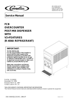
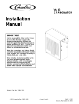
UNIT DESCRIPTION
The Unit (see Figure NO TAG) consists basically of two freeze cylinders each containing an internal beater
driven by an electric motor, one refrigeration system with a 2-horsepower compressor, one carbonator which
feeds both carbonator-blender tanks, a timer-controlled automatic hot-gas defrost system to defrost the freeze
cylinders, and interconnecting tubing, components, and fittings necessary to regulate, transfer, and dispense
product. The components are attached to a steel frame and are enclosed in a steel cabinet. The cabinet panels
are easily removed to facilitate installation and service and maintenance. A transparent faceplate, with an
integral relief valve and a removable self-closing dispensing valve, is mounted on front of each freeze cylinder.
A removable drip tray, with cup rest, is located directly below the dispensing valves.
CAUTION: Before shipping, storing, or relocating Unit, syrup systems must be sanitized
and all sanitizing solution must be purged from syrup systems. All water must also be
purged from plain and carbonated water systems. A freezing ambient environment will
cause residual sanitizing solution or water remaining inside Unit to freeze resulting in damage to
internal components.
FIGURE 1. FCB (SOLID-STATE) POST-MIX TWO-FLAVOR DISPENSER
Table 1. Design Data Table 2. Design Data
Part Number: Part Number:
60 Hz Unit 416120XXX
416120XXX
50 Hz Unit 496120XXX

326142000 2
Table 1. Design Data (cont’d)
Table 1. Design Data (cont’d)
Overall Dimensions: Overall Dimensions:
Height 60-1/2 inches
Width 19-1/4 inches
Depth Without Drip Tray 32-1/2 inches
Depth With Drip Tray 38 inches
Shipping Weight (approx.) 466 pounds
Compressor Horsepower 2 H.P.
Refrigeration System: Refrigeration System:
Refrigerant Type R-502
Refrigerant Charge See Unit Nameplate
Ambient Operating Temperature 40° F to 100° F
Electrical Requirements: Electrical Requirements:
60 Hz Unit:
Operating Voltage 219/242 VAC60 Hz Single Phase
Current Draw 21.2 Amps
50 Hz Unit:
Operating Voltage 219/242 VAC 50 Hz Single
Phase
Current Draw 22 Amps
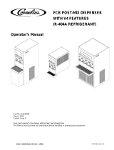
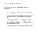
THEORY OF OPERATION
(see Figure 2)
IMPORTANT: Before connecting electrical power to Unit, refer to nameplate and note if Unit is to be
operated with 50 or 60 Hz power source and also note beaters drive motors manufacturer’s name. No.
6, No. 7, and No. 8 switches on DIP switch assembly on master circuit board must be set according to
motors manufacturer and for 50 or 60 Hz operation.
A CO2 cylinder delivers carbon dioxide (CO
2
) gas to an adjustable primary CO
2
regulator assembly attached to
the cylinder. Primary CO
2
regulator assembly in turn delivers CO
2
gas to adjustable secondary CO
2
regulators
inside the Unit and also to two soft drink tanks. CO
2
is delivered from adjustable secondary CO
2
regulators to
carbonator tank and also two product-blender tanks inside the Unit. CO
2
gas pressure pushes syrup out of soft
drink tanks, through syrup sold-out float switches, through electrically-operated syrup solenoid valves, through
adjustable syrup flow regulators, and on to product blender tanks. At the same time, plain water passes through
water pressure regulator and is pumped into carbonator tank by water pump and is carbonated by CO
2
gas
pressure also entering tank. Carbonated water is pushed by CO
2
gas pressure from carbonator tank, through
electrically operated carbonated water solenoid valves through adjustable carbonated water flow regulators, and
on to product blender tanks. Carbonated water and syrup enter tanks properly proportioned (blended) for
desired BRIX of dispensed product by adjustment of syrup flow regulators. From product blender tanks, product
is pushed by CO
2
gas into freeze cylinders. The beater in each freeze cylinder is driven by an electric motor.
Scraper blades, attached to beaters, scrapes product from cylinder walls as product enters freeze cylinders and
is frozen. Transparent faceplate, attached to front of each freeze cylinder, includes a self-closing dispensing
valve and a spring-loaded relief valve that protects freeze cylinder from accidental over pressure. The relief
valve is also used to bleed CO
2
gas pressure from freeze cylinder to atmosphere when filling cylinder with
product. Electronic sensing on each freeze cylinder motor provides a means of adjusting viscosity (consistency)
of dispensed product to suit customer preference.
DEFROST SYSTEMS
The Unit is equipped with both manual and automatic hot-gas defrost systems. The automatic defrost system
may be programmed into Unit to occur up to nine different times a day with a minimum of two hours between
defrost time settings or the system may be completely turned off.

3261420003
MANUAL DEFROST SYSTEM
The Manual hot-gas defrost system may be activated at any time by pressing ‘‘DEFROST’’ switch on front of
Unit. Refrigeration compressor will operate for a short time, then both freeze cylinders will go into defrost and
defrost for approximately 60-seconds. At end of manual defrost cycle, Unit will return to normal operation.
Manual defrost may be cancelled at any time by pressing ‘‘CANCEL DEFROST’’ switch.
AUTOMATIC DEFROST SYSTEM
The automatic hot-gas defrost system may be programmed into Unit to occur up to nine different times a day
with a minimum of two hours between defrost settings. At start of each automatic defrost cycle, refrigeration
compressor will operate for 30-seconds to pump freon out of freeze cylinders evaporator coils. After freon has
been pumped out of freeze cylinders evaporator coils, No. 1 freeze cylinders only will go into defrost cycle and
defrost for approximately 7-minutes, then will return to normal operation. This ends automatic defrost cycle of
No. 1 freeze cylinder. No. 2 freeze cylinder will defrost 30-minutes after the start of No. 1 freeze cylinder. The
next automatic defrost cycle will occur according to time programmed into the Unit. Automatic defrost may be
cancelled at any time by pressing ‘‘CANCEL DEFROST’’ switch.
‘‘SLEEP’’ (SLEEP TIME)
‘‘SLEEP’’ ((SLEEP TIME) may be programmed into Unit to allow Unit to go into sleep time (Unit shut down,
freeze cylinders beaters and refrigeration systems not operating). At start of sleep time, refrigeration
compressor will operate for 30-seconds to pump freon out of freeze cylinders evaporator coils, then No. 1 freeze
cylinder will go into defrost and defrost for 60-seconds. After No. 1 freeze cylinder has defrosted,, No. 2 freeze
cylinder will go into defrost and defrost for 60-seconds. At end of No. 2 freeze cylinder defrost, Unit will shut
down and go into sleep time.
‘‘WAKE UP’’ (WAKE UP TIME)
‘‘WAKE UP’’ (WAKE UP TIME) may be programmed into the Unit to allow Unit to resume normal operation at a
desired time. When programmed wake up time is reached, an alarm will sound for a short duration, then Unit
will resume normal operation.
NOTE: Automatic defrost, sleep time, and wake up time may be used in any combination together or
separately.

326142000 4
PRODUCT SAMPLE
VALVE (2)
PRODUCT
SHUTOFF
VALVE (2)
FREEZE
CYLINDER (2)
SYRUP FLOW
REGULATOR (2)
PRODUCT
BLENDER TANK (2)
CARBONATOR TANK
CO
2
PRESSURE
SWITCH
CO
2
CHECK
VALVE
SECONDARY CO
2
REGULATOR TO
CARBONATOR
TANKS (100-PSI)
SECONDARY CO
2
REGULATORS TO PRODUCT
BLENDER TANKS (60-PSI)
FREEZE CYLINDER
OVERFLOW TUBE
DOUBLE LIQUID
CHECK VALVE
LIQUID CHECK
VALVE (4)
CARBONATED WATER
FLOW REGULATOR (2)
CARBONATED WATER
SOLENOID VALVE (2)
SYRUP
SOLENOID VALVE (2)
SYRUP SOLD-OUT
FLOAT SWITCH (2)
SOFT DRINK
TANK (2)
CARBONATED WATER
VOLUME SAMPLE
VALVE
PRIMARY CO
2
REGULATOR
ASS’Y
CO
2
CHECK
VALVE (3)
CO
2
CYLINDER
SYRUP
SOLENOID VALVE (2)
CARBONATOR
WATER PUMP
*WATER
PRESSURE
REGULATOR
WATER
PRESSURE
SWITCH
SHUTOFF
VALVE
PLAIN WATER
SOURCE
*WATER PRESSURE REGULATOR IS FACTORY ADJUSTED
TO 45-PSI AND SHOULD NOT BE READJUSTED.
**SYRUP SOLD-OUT SWITCHES ARE FACTORY ADJUSTED
AND SHOULD NOT BE READJUSTED.
LINE LEGEND
CO
2
PLAIN WATER
CARB WATER
SYRUP
PRODUCT
FIGURE 2. FLOW DIAGRAM

3261420005
INSTALLATION
This section covers unpacking and inspection, installing LOOSE-SHIPPED PARTS, selecting location, installing
Unit, preparing for operation, and operation.
UNPACKING AND INSPECTION
(see Figure 5)
NOTE: The Unit was thoroughly inspected before leaving the factory and the carrier has accepted and
signed for it. Any damage or irregularities should be noted at time of delivery (or not later than 15 days
from date of delivery) and immediately reported to the delivering carrier. Request a written inspection
report from Claims Inspector to substantiate any necessary claim. File claim with the delivering carrier,
not with IMI Cornelius Inc.
1. After Unit has been unpacked, remove shipping tape and other packing material.
2. Remove Unit sides, top and back panels as instructed.
3. Remove shipping bolts that secure Unit to skid, then remove skid.
4. Unpack LOOSE-SHIPPED PARTS. Make sure all items are present and in good condition.
Table 3. Loose-Shipped Parts
Item
No. Part No. Name Qty.
1 178025-100 Tapered Gasket, White 4
2 151689 Spanner Wrench, Flow Regulator 1
3 322859 Spanner Wrench, Dispensing Valve 1
4 325216 Cleaning Brush 1
5 311304 Tapered Gasket, Black 1
6 325982 Cup Rest 1
7 325983-039 Drip Tray 1
8 325986 Drip Tray Support 2
9 319941 Thread Cutting Screw, Hex Hd, No. 8-32 by 3/8-in. long 4
10 325666 Instructions, Scraper Blades 1
11 325458 Beater (item 13) 2
12 325457 Scraper Blade (item 2) 4
13 325984 Frame, Drip Tray 1
14 326002 Kit, Drip Tray Drain Hose (includes items 15-19) 1
15 170413 Drain Fitting 1
16 151281 Lockwasher, Internal Tooth 1
17 170423 Hex Nut, 5/8-32 1
18 140133 Drain Hose Clamp 1
19 113500-039 Drain Hose, 1/2-in. I.D. by 60-in. long 1
*Numbers in parentheses are in reference to items in Figure 3).
IDENTIFICATION OF LOOSE-SHIPPED PARTS
1. TAPERED GASKETS, WHITE (item 1) are used to seal connections when connecting Unit product inlet
lines to product tanks and connecting Unit CO
2
inlet line to CO
2
source.

326142000
6
2. SPANNER WRENCH, FLOW REGULATORS (item 2) is used to adjust flow regulators inside Unit.
3. SPANNER WRENCH, DISPENSING VALVE (item 3) is used to remove shank nuts securing dispensing
valves to faceplates.
4. CLEANING BRUSH (item 4) is used to clean faceplate relief valves passages.
5. TAPERED GASKET, BLACK (item 5) is used to seal connection when connecting plain water source line to
Unit water inlet line.
6. DRIP TRAY SUPPORTS (item 8) to be installed on front of Unit and secured with THREAD CUTTING
SCREWS (item 9).
7. CUP REST (item 6) to be installed in DRIP TRAY (item 7), then drip tray to be installed in FRAME, DRIP
TRAY (item 13). Assembled drip tray assembly then to be installed on drip tray supports on front of Unit.
8. INSTRUCTIONS, SCRAPER BLADES (item 10) pictorially shows how to install BEATERS (item 11) and
SCRAPER BLADES (item 12) in freeze cylinders.
9. DRIP TRAY KIT (item 14) to be installed on drip tray as instructed.
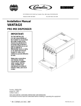
INSTALLING BEATERS (ITEM 11) AND SCRAPER BLADES (ITEM 12)
(see Figures 3 and 4)
1. Remove four HEX NUTS (item 7) and FLATWASHERS (item 6) that secure each faceplate to freeze
cylinders. Pull faceplates off freeze cylinders.
2. Position two SCRAPER BLADES (item 12) on BEATER (item 11 as shown in Figure 4.
3. Slide beater assembly into one of the freeze cylinders so beater slotted hooks engage DRIVE PIN (item
17) on DRIVE SHAFT (item 14) as shown in Figure 3.
4. Repeat procedure outlined in step 3 preceding to assemble and install beater assembly in other freeze
cylinder.
5. Lubricate each faceplate O-RING (see Figure 3 with Dow-Corning (DC 111) light grade silicone to facilitate
installing faceplates on freeze cylinders. Position each FACEPLATE On freeze cylinders so dispensing
valves faucets face down. Secure each faceplate to freeze cylinder with four HEX NUTS (item 7) and FLAT
WASHERS (item 6) removed in step 1 preceding. Tighten HEX NUTS until faceplates touch all the way
around on freeze cylinder flanges. CAUTION-DO NOT OVERTIGHTEN HEX NUTS.
ELECTRICAL POWER REQUIREMENTS
IMPORTANT: Before connecting electrical power to Unit, refer to nameplate and Note if Unit is to be
operated with 50 or 60 Hz power source and also note beaters motors manufacturer. No. 6, No. 7, and
No. 8 switches on DIP switch assembly on master circuit board must be set according to motors
manufacturer and for 50 or 60 Hz operation.
DOMESTIC UNIT
IMPORTANT: Power circuit voltage across L
1
and L
2
terminals on contactor inside lower control box,
with refrigeration compressor operating, must be in operating range of between 219/242 VAC, 60 Hz
single-phase range for proper operation. If voltage is below or above this range, a .75 KVA Step
Up/Step Down Transformer (P/N 326138000) is available to correct below or above voltage condition.

7
326142000
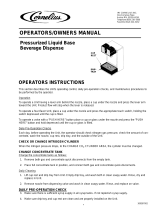
1. Product Inlet Fitting
2. Scraper Blade (2)
3. Evaporator Coi.l
4. Relief Valve Port
5. O-Ring
6. Flatwasher (4)
7. Hex Nut (4)
8. Faceplate
9. Relief Va;ve
10. Valve Lever
11. Knob
12. Dispensing Valve
13. Beater
14. Drive Shaft Seal Assembly
15. Allen Head Setscrew
16. Beater Shaft Coupling
17. Drive Pin
18. Bearing Guide Pin (4)
19. Power Coupler (plastic)
20. Beater Motor Drive Shaft
21. Beater Drive Motor Shaft Coupling
22. Beater Drive Motor
23. Unit Frame
24. Drive Shaft Assembly
25. Viscosity Sensor
26. Spinner
27. spring
28. Shaft Release
FIGURE 3. FREEZE CYLINDER CUTAWAY VIEW

8326142000
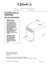
KEY ON END
OF POST
BEATER
KEY ON END
OF POST
KEY SLOT
ON BLADE
SCRAPER BLADES MUST BE MOUNTED TO THE
BEATER BODY AS SHOWN USING THE PERFO-
RATED EDGE AS THE LEADING EDGE. LINE UP
KEY ON END OF POSTS WITH KEY SLOT IN
SCRAPER BLADES.
FIGURE 4. BEATERS AND SCRAPER BLADES INSTALLATION
A properly grounded 219 to 242 VAC, 60Hz single-phase electrical circuit with a 30-amp minimum-rated
disconnect switch (not provided) fused at 30 amps (slo-blow) or circuit connected through an equivalent HACR
circuit breaker must be available to the Unit. ALL WIRING MUST CONFORM TO NATIONAL AND LOCAL
CODES. MAKE SURE UNIT IS PROPERLY GROUNDED.
EXPORT UNIT
IMPORTANT: Power circuit voltage across L
1
and L
2
terminals on contactor inside lower control box,
with refrigeration compressor operating, must be in operating range of between 219 and 242 VAC, 50Hz
single-phase range for proper operation. If voltage is below or above this range. A means to provide
voltage within operating range must be provided.
A properly grounded 219 to 242 VAC, 50Hz single-phase electrical circuit with a 30-amp minimum-rated
disconnect switch (not provided) fused at 30-amps (slow-blow) must be available to the Unit.
SELECTING LOCATION
IMPORTANT: Unit operating ambient temperature MUST NOT EXCEED 100° F. Several means are
available to achieve proper ambient temperature and air circulation around the Unit which are wall air
intake grilles and ceiling exhaust fans, air conditioning, etc. Consult local codes.
Locate Unit so the following requirements are satisfied.

9 326142000
1. Close to a plain water inlet supply line with a minimum pressure of 12-psig.
NOTE: Circulating air, required to cool the refrigeration system’s condenser coil, is drawn in through
grille on front and exhausted out through sides and back of Unit. Restricting air circulation through the
Unit will decrease its cooling efficiency.
2. When installing Unit, do not allow obstruction to block grille on front which will block off air intake to inside
of Unit. If installation dictates only one side or back being unobstructed, allow 18-inches clearance between
Unit and obstruction. If both sides or one side and back are unobstructed, allow 12-inches clearance. If
both sides and back are unobstructed, allow 6-inches clearance.
INSTALLING UNIT
PLACING UNIT IN OPERATING LOCATION
1. Place Unit in operating location meeting requirements of SELECTING LOCATION.
2. After Unit has been placed in operating location, make sure front (dispensing valve side) is 1/4 to 3/8-inch
higher than the back to eliminate gas pockets being trapped inside the freeze cylinders.
3. To comply with National Sanitation Foundation (NSF) requirements, Unit installed with base contacting floor
must have base sealed to floor with Dow Corning RTV 731 or equivalent.
INSTALLING DRIP TRAY SUPPORTS, DRIP TRAY, AND CUP REST
1. Install DRIP TRAY SUPPORTS (item 8) on panel above lower front access panel on front of Unit. Secure
supports to panel with THREAD CUTTING SCREWS (item 9).
2. Place DRIP TRAY (item 7) in FRAME, DRIP TRAY (item 13), then slide frame up on drip tray supports on
front of Unit.
INSTALLING DRIP TRAY DRAIN KIT (ITEM 14)
(see Figure 5)
1. Drill 5/8-inch diameter hole in lowest point (center) in bottom of drip tray.
2. Install DRAIN FITTING (item 15) in drip tray and secure with LOCKWASHER, INTERNAL TOOTH (item
16) and HEX NUT, 5/8-32 (item 17).
3. Push DRAIN HOSE (item 17) over drip tray fitting and secure with DRAIN HOSE CLAMP (item 18).
NOTE: Drip tray drain hose may be routed to a waste container, but is not recommended due to
sanitation and cleaning problems. Connection of drain hose to a permanent drain is most highly
recommended.
4. Route drip tray drain hose to and connect to permanent drain.
5. Place CUP REST (item 6) in drip tray.
INSTALLING PRIMARY CO
2
REGULATOR ASSEMBLY ON CO
2
CYLINDER
(see Figure 2)
WARNING: To avoid personal injury and/or property damage, always secure CO
2
cylinder in
upright position with a safety chain to prevent it from falling over. Should the valve become
accidentally damaged or broken off, CO
2
cylinder can cause serious personal injury.

10326142000
WARNING: CO
2
displaces oxygen. Strict attention must be observed in the prevention of
CO
2
(carbon dioxide) gas leaks in the entire CO
2
and soft drink system. If a CO
2
gas leak is
suspected, particularly in a small area, immediately ventilate the contaminated area before
attempting to repair the leak. Personnel exposed to high concentration of CO
2
gas will experience
tremors which are followed rapidly by loss of consciousness and suffocation.
1. Unscrew protector cap (with chain attached) from CO
2
cylinder valve. Open CO
2
cylinder valve slightly
counterclockwise to blow any dirt or dust from outlet fitting before installing primary CO
2
regulator, then
close valve.
2. Remove shipping plug from primary CO
2
regulator assembly coupling nut and make sure gasket is in place
inside nut. Install regulator assembly on CO
2
cylinder so gages can be easily read, then tighten coupling
nut. DO NOT OPEN CO
2
CYLINDER VALVE AT THIS TIME.
CONNECTING SOFT DRINK TANKS CO
2
LINES TO PRIMARY CO
2
REGULATOR
ASSEMBLY
(see Figure 2)
1. Connect soft drink tanks CO
2
lines to primary CO
2
regulator manifold assembly as shown in Figure 2.
2. Install gas quick disconnects on ends of soft drink tanks CO
2
lines. DO NOT CONNECT CO
2
LINES TO
TANKS AT THIS TIME.
PREPARING UNIT SYRUP INLET LINES FOR CONNECTION TO SOFT DRINK TANKS
(see Figure 2)
1. Route Unit syrup inlet lines, labeled No. 1 and No. 2, out through hole provided in Unit base to soft drink
tanks location.
2. Install liquid disconnects on ends of Unit syrup inlet lines. DO NOT CONNECT SYRUP LINES TO TANKS
AT THIS TIME.
CONNECTING PLAIN WATER INLET SUPPLY LINE TO UNIT
(see Figure 2)
NOTE: IMI Cornelius Inc. recommends that a water shutoff valve and water filter be installed in plain
water inlet supply line (see Figure 2). A Cornelius Water Filter (P/N 313860000) and Quick Disconnect
Set (P/N 313867000) are recommended.
1. Before connecting plain water inlet supply line to Unit, open shutoff valve in water supply line for a period of
time to flush out any metal shavings.
2. Route water inlet line out through hole in bottom of Unit base.
NOTE: Carbonator plain water inlet adjustable water pressure regulator (see Figure 12) is factory
adjusted to 45-psi and should not be readjusted.
3. Connect Unit water inlet line to plain water inlet supply line (12-psi minimum pressure). Seal connection
with TAPERED GASKET, BLACK (item 5). DO NOT OPEN WATER INLET SUPPLY LINE SHUTOFF
VALVE AT THIS TIME.

11 326142000
CONNECTING ELECTRICAL POWER CIRCUIT TO UNIT
(see Figure 17)
WARNING: Make sure Unit 30-amp minimum-rated disconnect switch (not provided) or
equivalent HACR circuit breaker is in ‘‘OFF’’ position.
Domestic Unit.
IMPORTANT: Power circuit voltage across L
1
and L
2
terminals on contactor inside lower control box,
with refrigeration compressor operating, must be in operating range of between 219 and 242 VAC, 60Hz
single-phase range for proper operation. If voltage is below or above this range, a .75 KVA Step
Up/Step Down Transformer (P/N 326138-000) is available to correct below or above voltage condition.
Use No. 10 AWG copper wire, or larger, depending upon line length, in suitable conduit or BX sheath.
POWER CIRCUIT TO UNIT MUST BE MADE UP OF COPPER CONDUCTORS AND ALL WIRING MUST
CONFORM TO NATIONAL AND LOCAL CODES.
Export Unit.
IMPORTANT: Power circuit voltage across L
1
and L
2
terminals on contactor inside lower control box,
with refrigeration compressor operating, must be in operating range of between 219 and 242 VAC, 50Hz
single-phase range for proper operation. If voltage is below or above this range. A means to provide
voltage within operating range must be provided.
1. Remove lower control box (located on lower-right side facing front of Unit) cover for access to contactor L
1
and L
2
terminals.
WARNING: This Unit must be electrically grounded to avoid possible fatal electrical shock
or serious injury to the operator. A green screw, with lock washer, is provided inside
control box to connect power circuit ground wire electrically grounding the Unit.
2. Connect electrical power from 30-amp minimum-rated disconnect switch (not provided) fused at 30-amps
(slo-blow) or through an equivalent HACR circuit breaker to L
1
and L
2
terminals on contactor inside control
box. MAKE SURE GROUND WIRE IS CONNECTED TO GREEN GROUND SCREW INSIDE CONTROL
BOX.
3. Install lower control box cover and secure with screws.
PREPARATION FOR OPERATION
50 OR 60 HZ OPERATION AND BEATER MOTOR SELECT
IMPORTANT: Before connecting electrical power to Unit, refer to Unit nameplate and note if Unit is to
be operated with 50 or 60 Hz electrical power and also note beater motor manufacturer’s name. No. 6,
No.7, and No. 8 switches on DIP switch assembly on master circuit board must be set according to
motor manufacturer and for 50 or 60 Hz operation as follows.
1. Remove four screws securing Unit upper control box cover, then remove cover for access to the master
circuit board (see Figure 10).
2. After noting if Unit is to be operated with 50 or 60 Hz electrical power and beater motors manufacturer’s
name, refer to Figure 10 and Table 5 to place DIP switch assembly No. 6, No. 7, and No. 8 switches in
appropriate positions.

12326142000
TURNING ON ELECTRICAL POWER TO UNIT
Turn on electrical power to Unit. Operational status of Unit is now being displayed as fault messages on control
panel message display. The following fault messages will be continuously displayed at 2-second intervals until
necessary operation requirements are satisfied.
‘‘OFF 1’’ (Beater Motor No. 1 not operating)
‘‘OFF 2’’ (Beater Motor No. 2 not operating)
‘‘H
2
O OUT’’ (No water supply to Unit)
‘‘CO
2
OUT’’ (No CO
2
gas supply to Unit)
‘‘SYRUP 1’’ (No syrup supply to Unit No. 1 syrup system)
‘‘SYRUP 2’’ (No syrup supply to Unit No. 2 syrup system)
TURNING ON CO
2
SUPPLY TO UNIT
1. Open CO
2
cylinder valve slightly to allow lines to slowly fill with gas, then open valve fully to back seat
valve. Back-seating valve prevents leakage around valve shaft.
IMPORTANT: If bag-n-box syrup supply system will be connected to Unit instead of soft drink tanks,
primary CO
2
regulator (see Figure 2) must be adjusted no higher than 80-psi maximum.
2. Adjust primary CO
2
regulator (see Figure 2) by turning regulator adjusting screw to the right (clockwise)
until regulator pressure reads 80 to 100-psig. OUT OF CO
2
warning light on control panel message display
should have gone out.
3. Pull up on product blender tanks relief valves to purge air from tanks.
4. Remove Unit lower access panel as instructed for access to carbonator secondary CO
2
regulators (see
Figures 2 and 6).
5. Check product blender tanks secondary CO
2
regulators with 60-psi gages for pressure setting which
should be set at 30-psi for best textured product. If further adjustment is necessary, adjust as instructed.
IMPORTANT: Carbonator secondary CO
2
regulator must be adjusted 25-psi higher or more above
product blender tanks secondary CO
2
regulators pressure settings. Carbonated water and syrup
pressures must be able to overcome and vent product blender tanks head pressures while tanks are
filling with carbonated water and syrup. Carbonator tank secondary CO
2
regulator not adjusted high
enough will cause decreased flow of carbonated water into blender tanks which will increase brix of
dispensed product.
6. Adjust carbonator secondary CO
2
regulator, with 100-psi gage, by turning regulator adjusting screw to the
right (clockwise) until gage reads 60-psi.
7. Pull up on carbonator tank relief valve plastic cover to purge air from tank.
TURNING ON PLAIN WATER SUPPLY TO UNIT
Open plain water inlet supply line shutoff valve. Check for water leaks and tighten or repair if evident. ‘‘H
2
O
OUT’’ fault message should have gone out but ‘‘BM 1 OFF’’, ‘‘BM 2 OFF’’, ‘‘SYRUP 1’’, and ‘‘SYRUP 2’’ fault
messages will continue to be displayed.
CONNECTING SOFT DRINK TANKS TO UNIT SYRUP SYSTEMS
IMPORTANT: Product shutoff valves, located in lines leading from product blender tanks to freeze
cylinders (see Figure 2 and 6), must be closed at this time. Closing valves prevents product from filling
freeze cylinders while checking BRIX of product in product blender tanks.
1. Close product shutoff valves, located in lines leading from product blender tanks to freeze cylinders, to
prevent product from entering cylinders.

13 326142000
IMPORTANT: The following CO
2
and liquid disconnects disconnecting and connecting procedure for
soft drink tank replacement or filling soft drink tank in place must be performed in order as follows:
To disconnect soft drink tank from Unit syrup system.
A. Disconnect liquid disconnect from soft drink tank. NOTE - Disconnecting liquid quick
disconnect from soft drink tank first prevents syrup from backflowing through Unit syrup flow
regulator which may alter regulator adjustment.
B. Second, disconnect CO
2
quick disconnect from soft drink tank.
NOTE: Unit control panel is equipped with a hidden ‘‘SECURITY SWITCH’’ located between ‘‘FILL 1’’
and ‘‘ERROR RESET’’ control switches (see Figure 5). Pressing in and holding ‘‘SECURITY SWITCH’’
for 3-seconds deactivates control switches preventing tampering with Unit normal operation. To
reactivate control switches, press in and hold ‘‘SECURITY SWITCH’’ for 3-seconds.
2. Pressurize soft drink tanks containing syrup, then connect tanks to Unit syrup systems. ‘‘OFF 1’’, ‘‘OFF 2’’,
‘‘SYRUP 1’’, and ‘‘SYRUP 2’’ fault messages will continue to be displayed.
ADJUSTING BRIX (WATER-TO-SYRUP) ‘‘RATIO’’ OF DISPENSED PRODUCT
The following steps 1 through 9 are instructions for adjusting Brix (Water-to-Syrup ‘‘Ratio’’ (mixture) of
dispensed product on one system.
1. Press ‘‘FILL 1’’ switch to fill No. 1 syrup system sold-out float. ‘‘SYRUP 1’’ fault message will go out and
‘‘FILL 1’’ fault message will come on. ‘‘OFF 1’’, ‘‘OFF 2’’, and ‘‘SYRUP 2’’ fault messages will continue to be
displayed.
2. Press ‘‘AUTO BLEND 1’’ switch to fill No. 1 system product blender tank with product. ‘‘FILL 1’’ fault
message will go out when ‘‘AUTO BLEND 1’’ switch is pressed. When product blender tank is full, press
‘‘FILL 1’’ switch to prevent more product from entering tank. ‘‘OFF 1’’, ‘‘OFF 2’’, and ‘‘SYRUP 2’’ fault
messages will continue to be displayed.
3. Open No. 1 product blender tank product sample valve (see Figures 2 and 6) and take sample
(approximately 6-ounces) of product in cup or glass.
NOTE: Temperature compensated hand-type refractometers (P/N 511004000) are available from The
Cornelius Company.
4. Check product BRIX with a temperature compensated hand-type refractometer. BRIX should read 13.5 ±
0.5. If BRIX is not within tolerance, adjust white syrup flow regulator for No. 1 syrup system as follows:
A. Loosen jamb nut on syrup flow regulator.
B. Turn regulator adjusting screw to the left (counterclockwise) no more than 1/8-turn at a time to reduce
syrup flow rate or turn screw to the right (clockwise) no more than 1/8-turn to increase flow rate.
C. Tighten jamb nut on syrup flow regulator, then lightly tap regulator to register adjustment.
5. Place container under No. 1 product sample valve. Open valve to purge product out of product blender
tank, line, and valve, then close valve. ‘‘OFF 1’’, ‘‘OFF 2’’, and ‘‘SYRUP 2’’ will continue to be displayed.
6. Press ‘‘AUTO BLEND 1’’ switch to run new batch of product into product blender tank. When product
blender tank is full, press ‘‘FILL 1’’ switch to prevent more product from entering product blender tank.
‘‘OFF 1’’, ‘‘OFF 2’’, and ‘‘SYRUP 2’’ fault messages will continue to be displayed.
7. Repeat steps 3 and 4 preceding to check product sample for BRIX.
8. Repeat steps 5 through 7 preceding until proper BRIX adjustment is achieved.
9. Repeat steps 1 through 8 preceding to adjust BRIX of dispensed product on No. 2 system. After
completing BRIX on No. 2 system, ‘‘OFF 1’’ and ‘‘OFF 2’’ fault messages should continue to be displayed.
/