Page is loading ...

EIMI Cornelius Inc.; 1982-2001
April 1,1982
Revised: November 30, 2001
Control Code D
CARBONATOR
Installation
Manual
Manual Part No. 318511001
VA 13
IMPORTANT:
It is the responsibility of the Service Person
to ensure that the water supply to the
dispensing equipment is provided with
protection against backflow by an air gap as
defined in ANSI/ASME A112. 1.2-1979; or an
approved vacuum breaker or other such
method as proved effective by test.
Water pipe connections and fixtures directly
connected to a potable water supply shall be
sized, installed, and maintained according to
Federal, State, and Local codes.
When installing in an area regulated by the
City of Los Angeles Plumbing and/or
Mechanical Codes, a City of Los Angeles
approved reduced pressure principle
backflow preventer shall be installed on each
potable water supply to each carbonator.

i
318511001
TABLE OF CONTENTS
Page
SAFETY INFORMATION 1. . . . . . . . . . . . . . . . . . . . . . . . . . . . . . . . . . . . . . . . . . . . . . . . . . . .
RECOGNIZE SAFETY INFORMATION 1. . . . . . . . . . . . . . . . . . . . . . . . . . . . . . .
UNDERSTAND SIGNAL WORDS 1. . . . . . . . . . . . . . . . . . . . . . . . . . . . . . . . . . . .
FOLLOW SAFETY INSTRUCTIONS 1. . . . . . . . . . . . . . . . . . . . . . . . . . . . . . . . .
CO2 (CARBON DIOXIDE) WARNING 1. . . . . . . . . . . . . . . . . . . . . . . . . . . . . . . .
SHIPPING, STORING, OR RELOCATING UNIT 1. . . . . . . . . . . . . . . . . . . . . . .
GENERAL INFORMATION 3. . . . . . . . . . . . . . . . . . . . . . . . . . . . . . . . . . . . . . . . . . . . . . . . . .
TO THE USER OF THIS MANUAL 3. . . . . . . . . . . . . . . . . . . . . . . . . . . . . . . . . . . . . . .
CLAIMS INSTRUCTIONS 3. . . . . . . . . . . . . . . . . . . . . . . . . . . . . . . . . . . . . . . . . . . . . .
WARRANTY REFERENCE INFORMATION 3. . . . . . . . . . . . . . . . . . . . . . . . . . . . . . .
DESIGN DATA 3. . . . . . . . . . . . . . . . . . . . . . . . . . . . . . . . . . . . . . . . . . . . . . . . . . . . . . . .
UNIT DESCRIPTION 4. . . . . . . . . . . . . . . . . . . . . . . . . . . . . . . . . . . . . . . . . . . . . . . . . . .
THEORY OF OPERATION 5. . . . . . . . . . . . . . . . . . . . . . . . . . . . . . . . . . . . . . . . . . . . . .
INSTALLATION 7. . . . . . . . . . . . . . . . . . . . . . . . . . . . . . . . . . . . . . . . . . . . . . . . . . . . . . . . . . . .
UNPACKING AND INSPECTION 7. . . . . . . . . . . . . . . . . . . . . . . . . . . . . . . . . . . . . . . .
IDENTIFICATION OF LOOSE–SHIPPED PARTS 7. . . . . . . . . . . . . . . . . . . . . . . . . .
SELECTING LOCATION 7. . . . . . . . . . . . . . . . . . . . . . . . . . . . . . . . . . . . . . . . . . . . . . . .
INSTALLING THE UNIT 7. . . . . . . . . . . . . . . . . . . . . . . . . . . . . . . . . . . . . . . . . . . . . . . .
PLACING UNIT IN OPERATING LOCATION 7. . . . . . . . . . . . . . . . . . . . . . . . . .
CONNECTING PLAIN WATER INLET SUPPLY LINE TO UNIT 8. . . . . . . . . .
CONNECTING CO2 INLET SUPPLY LINE 9. . . . . . . . . . . . . . . . . . . . . . . . . . . .
CONNECTING CARBONATED WATER OUTLET LINE 9. . . . . . . . . . . . . . . .
PERMANENT ELECTRICAL POWER CONNECTION TO DOMESTIC UNIT IF
REQUIRED BY LOCAL CODES 9. . . . . . . . . . . . . . . . . . . . . . . . . . . . . . . . . . . . . . . . .
PREPARATION FOR OPERATION 11. . . . . . . . . . . . . . . . . . . . . . . . . . . . . . . . . . . . . . .
ADJUSTING CARBONATOR CO2 REGULATOR AND TURN PLAIN
WATER INLET LINE ON 11. . . . . . . . . . . . . . . . . . . . . . . . . . . . . . . . . . . . . . . . . . . .
UNIT OPERATION 11. . . . . . . . . . . . . . . . . . . . . . . . . . . . . . . . . . . . . . . . . . . . . . . . . . . . .
TROUBLESHOOTING 15. . . . . . . . . . . . . . . . . . . . . . . . . . . . . . . . . . . . . . . . . . . . . . . . . . . . . .
WATER PUMP MOTOR WILL NOT OPERATE. 15. . . . . . . . . . . . . . . . . . . . . . . . . . . .
WATER PUMP MOTOR WILL NOT SHUT OFF. 15. . . . . . . . . . . . . . . . . . . . . . . . . . .
ERRATIC CYCLING OF CARBONATOR. 16. . . . . . . . . . . . . . . . . . . . . . . . . . . . . . . . .
WATER PUMP MOTOR OPERATES BUT WATER PUMP DOES NOT PUMP
WATER. 16. . . . . . . . . . . . . . . . . . . . . . . . . . . . . . . . . . . . . . . . . . . . . . . . . . . . . . . . . . . . . .
WATER PUMP CAPACITY TOO LOW. 16. . . . . . . . . . . . . . . . . . . . . . . . . . . . . . . . . . .
WARRANTY 17. . . . . . . . . . . . . . . . . . . . . . . . . . . . . . . . . . . . . . . . . . . . . . . . . . . . . . . . . . . . . .
LIST OF FIGURES
FIGURE 1. VA 13 CARBONATOR 4. . . . . . . . . . . . . . . . . . . . . . . . . . . . . . . . . . . . . . . .
FIGURE 2. CARBONATOR CONNECTIONS 9. . . . . . . . . . . . . . . . . . . . . . . . . . . . . .
FIGURE 3. CARBONATOR ASSEMBLY COMPONENTS 10. . . . . . . . . . . . . . . . . . .
FIGURE 4. WIRING DIAGRAM (MODEL NO. 416411000,1621, and 496411000) 13

ii
318511001
TABLE OF CONTENTS (cont’d)
Page
LIST OF FIGURES CONT’D)
FIGURE 5. WIRING DIAGRAM (MODEL NO. 496411020) 13. . . . . . . . . . . . . . . . . . .
FIGURE 6. WIRING DIAGRAM (MODEL NO. 496411040) 14. . . . . . . . . . . . . . . . . . .
LIST OF TABLES
TABLE 1. DESIGN DATA 3. . . . . . . . . . . . . . . . . . . . . . . . . . . . . . . . . . . . . . . . . . . . . . .
TABLE 2. LOOSE-SHIPPED PARTS 7. . . . . . . . . . . . . . . . . . . . . . . . . . . . . . . . . . . . .

1 318511001
SAFETY INFORMATION
Recognize Safety Information
This is the safety-alert symbol. When you see this
symbol on our machine or in this manual, be alert to
the possibility of personal injury.
Follow recommended precautions and safe operating
practices.
DANGER
Understand Signal Words
A signal word - DANGER, WARNING, OR CAUTION
is used with the safety-alert symbol. DANGER identi-
fies the most serious hazards.
Safety signs with signal word DANGER or WARNING
are typically near specific hazards.
WARNING
General precautions are listed on CAUTION safety
signs. CAUTION also calls attention to safety mes-
sages in this manual.
CAUTION
Follow Safety Instructions
Carefully read all safety messages in this manual and on your machine safety signs. Keep safety signs in
good condition. Replace missing or damaged safety signs. Learn how to operate the machine and how to
use the controls properly. Do not let anyone operate the machine without instructions. Keep your machine in
proper working condition. Unauthorized modifications to the machine may impair function and/or safety and
affect the machine life.
CO
2
(Carbon Dioxide) Warning
CO
2
Displaces Oxygen. Strict Attention must be observed in the prevention of CO
2
(carbon dioxide)
gas leaks in the entire CO
2
and soft drink system. If a CO
2
gas leak is suspected, particularly in a
small area, immediately ventilate the contaminated area before attempting to repair the leak. Person-
nel exposed to high concentration of CO
2
gas will experience tremors which are followed rapidly by
loss of consciousness and suffocation.
CAUTION: All water must be purged from the Unit if exposed to freezing temperature. A freezing am-
bient temperature will cause residual water remaining inside the Unit to freeze resulting in damage to
internal components of the Unit.
Shipping, Storing, Or Relocating Unit

2
318511001
THIS PAGE LEFT BLANK INTENTIONALLY

3 318511001
GENERAL INFORMATION
TO THE USER OF THIS MANUAL
This Manual is a guide for servicing and maintaining this equipment. Refer to Table Of Contents for page loca-
tion of detailed information pertaining to questions that may arise. A Service Manual (P/N 318511005) for this
equipment is available upon request.
This Unit must be serviced by a qualified Service Person. This Unit contains no User serviceable parts.
CLAIMS INSTRUCTIONS
Claims: In the event of shortage, notify the carrier as well as IMI Cornelius immediately. In the event of dam-
age, notify the carrier. IMI Cornelius is not responsible for damage occurring in transit, but will gladly
render assistance necessary to pursue your claim. Merchandise must be inspected for concealed dam-
age within 15 days of receipt.
WARRANTY REFERENCE INFORMATION
Warranty Registration Date
(to be filled out by customer)
Unit Part Number:
Serial Number:
Install Date:
Local Authorized
Service Center:
DESIGN DATA
Table 1. Design Data
Model Numbers
115 VAC Unit (Liquid dual check valve) 416411000
115 VAC Unit (With vented dual check valve) 1621
230 VAC Unit (Liquid dual check valve) 496411000
230 VAC Unit (Liquid dual check valve) 496411020
230 VAC Unit (Liquid dual check valve) 496411040

4
318511001
Table 1. Design Data (cont’d)
Overall Dimensions:
Width 6-3/8 inches
Height 15 inches
Depth 14 inches
Weight:
Dry 28-3/4 pounds
Shipping 30-1/4 pounds
Ambient Operating Temperature 40° F to 100° F
Maximum Operating CO
2
Pressure 125 PSI
Electrical Requirements:
Operating Voltage and Current Draw See Unit Nameplate
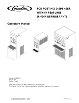
FIGURE 1. VA 13 CARBONATOR
UNIT DESCRIPTION
The carbonator is a compact Unit that may be installed in a remote location from where its carbonated water
outlet is to be connected to a post-mix dispenser or a system. The purpose of the Unit is to mix plain water and
carbon dioxide (CO
2
) gas which results in and provides carbonated water for a post-mix dispenser or a system.
The Unit consists basically of a water pump, motor, and a carbonated water tank. The water pump has a liquid
dual check valve (Unit Model No. 416411000, 496411000, 496411020, and 496411040) or a Vented Dual Check
Valve (Unit Model No. 1621) on its outlet to prevent carbonated water from back flowing into the city water sys-
tem. The Vented Dual Check Valve vents water and possibly CO
2
gas out of a vent port on failure of the primary
check valves. Should such venting occur, the primary check valve should be replaced. The Unit CO
2
inlet has a
single check valve to prevent carbonated water back flow into the CO
2
regulator.

5 318511001
THEORY OF OPERATION
A CO
2
cylinder delivers carbon dioxide (CO
2
) gas through an adjustable CO
2
regulator to the carbonated water
tank. At the same time, plain water is pumped into the carbonated water tank by the water pump and is carbon-
ated by CO
2
gas also entering the tank. Carbonated water enters the tank until the weight of the water in the
tank forces the tank and balance control mechanism down to activate the level control switches. Activating the
level control switches disrupts electrical power to and stops the water pump motor. As carbonated water is dis-
pensed from the tank, the tank becomes lighter allowing the tank and balance control mechanism to rise which
again activates the level control switches. Activating the level control switches restores electrical power to the
water pump motor allowing the carbonated water tank to be replenished.

6
318511001
THIS PAGE LEFT BLANK INTENTIONALLY

7 318511001
INSTALLATION
UNPACKING AND INSPECTION
NOTE: This Unit was thoroughly inspected before leaving the factory and the carrier has accepted and
signed for it. Any damage or irregularities should be noted at the time of delivery and immediately re-
ported to the delivering carrier. Request a written inspection report from the Claims Inspector to sub-
stantiate any necessary claim. File the claim with the delivering carrier, not IMI Cornelius Inc.
1. After unit has been uncrated, remove shipping tape and other packing material. Check for obvious damage
and follow procedure in preceding NOTE if damage is evident.
2. Unpack LOOSE–SHIPPED PARTS. Make sure items are present and in good condition.
Table 2. Loose-Shipped Parts
Item
No. Part No. Name Qty.
1 178025100 Tapered Gasket, White 2
2 311304000 Tapered Gasket, Black 1
IDENTIFICATION OF LOOSE–SHIPPED PARTS
1. TAPERED GASKETS, WHITE (item 1) are used to seal connections when connecting lines to fittings la-
beled CO
2
INLET and CARB WATER OUTLET on the Unit.
2. TAPERED GASKET, BLACK (item 2) is used to seal connection when connecting plain water inlet supply
line to the Unit.
SELECTING LOCATION
Locate unit so following requirements are satisfied.
1. Locate the Unit in a cool area close to a properly grounded electrical outlet with proper electrical require-
ments fused at 15-amps (slow-blow). No other electrical appliance should be connected to this circuit. For
accessibility, the electrical outlet must not be located behind the Unit. ALL WIRING MUST CONFORM TO
NATIONAL AND ELECTRICAL CODES.
2. Locate the Unit close to a plain water source line with requirements as outlined in CAUTION note under
CONNECTING PLAIN WATER INLET LINE TO UNIT. Plain water inlet line from plain water source line to
the Unit should be 3/8-inch I.D. (minimum) food-grade plastic.
3. Locate the Unit close to a permanent drain if installing Unit (P/N 1621) which is equipped with a vented
Dual-Check Valve which must have it’s vent tube routed to a permanent drain.
INSTALLING THE UNIT
PLACING UNIT IN OPERATING LOCATION

8
318511001
CAUTION: This Unit must not be installed in an unsheltered outdoor location where it will
be exposed to the elements.
IMPORTANT: Before putting carbonator into operation, carbonator cover must be removed and packing
block must be removed from below the water pump motor.
1. Place carbonator in operating location meeting requirements of SELECTING LOCATION. MAKE SURE
CARBONATOR IS SITTING IN LEVEL POSITION FOR PROPER OPERATION.
2. Remove two screws securing the cover assembly on the Unit, then remove the cover.
3. Remove packing block from below the water pump motor.
4. Install cover assembly on the Unit and secure with two screws.
5. Unit Model No. 1621.
IMPORTANT: A vented dual-check valve assembly is installed in this carbonator between the water
pump outlet and the water inlet to the carbonator tank as shown in Figure 3. The vented dual-check
valve assembly vents carbonated water, and possibly CO
2
gas out of a vent port upon failure of the
primary check valves. Should such venting occur, the vented dual-check valve assembly must be
replaced.
CAUTION: Route free end of the vented dual–check valve vent tube to a permanent drain to
avoid serious water damage in the event of a check valve failure.
Route free end of the vented dual-check valve vent tube, protruding out the end of the carbonator cabinet, to a
permanent drain. TO AVOID POSSIBLE BACK-SUCTION FROM THE PERMANENT DRAIN, LOCATE THE
END OF THE VENTED DUAL-CHECK VALVE VENT TUBE ABOVE THE DRAIN OR AS REQUIRED BY THE
LOCAL PLUMBING CODE.
CONNECTING PLAIN WATER INLET SUPPLY LINE TO UNIT
CAUTION: Check minimum flow rate and maximum pressure of the plain water inlet supply
line. MINIMUM FLOW RATE MUST BE AT LEAST 100-GALLONS PER HOUR. If flow rate is
less than 100-gallons per hour, starving of the carbonator water pump will occur. Starving
will allow the carbonator water pump to overheat causing the safety thermostat on the water pump
outlet to disrupt electrical power to and stop the water pump motor. Overheating could occur if the
plain water inlet supply line flow rate drops below 100-gallons per hour. WATER PRESSURE MUST
BE 10-PSI LESS THAN THE CO
2
PRESSURE. (Example: operating CO
2
pressure is 80-psi,
maximum water pressure can be no more than 70-psi, etc.). Water over pressure (higher than
operating pressure) can cause carbonator flooding, malfunction, and leakage through the
carbonator tank relief valve. If water is exceeding maximum pressure specifications, a Water
Pressure Regulator Kit (P/N 310150000) or equivalent must be installed in the plain water inlet
supply line. If fitting connector is not available, tap into the plain water supply line with a 3/8-flare
saddle valve (P/N 315664000) or equivalent.
NOTE: IMI Cornelius Inc. recommends that a water shutoff valve and water filter be installed in the
plain water inlet supply line (see Figure 2) . A Cornelius Water Filter (P/N 313860000) and Quick Dis-
connect Set (P/N 313867000) are recommended.
1. Make sure food grade flexible plastic 3/8-inch I.D. (minimum) plain water inlet line provides adequate water
flow rate and pressure as outlined in CAUTION note.

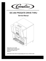
9 318511001
CO
2
INLET
POWER CORD
PLAIN WATER INLET
CARB (CARBONATED)
WATER
FIGURE 2. CARBONATOR CONNECTIONS
Before connecting plain water inlet line to the Unit, open the water line for a period of time to flush out any
metal shavings resulting from connecting the water line to the fitting connector or saddle valve.
2. Remove shipping cap from the 3/8-inch flare (5/8-18) male fitting on the Unit labeled “WATER
INLET”.
3. Install TAPERED GASKET (item 2) in the plain water inlet line swivel nut, then connect the water line to the
3/8-flare male fitting labeled “WATER INLET” on the Unit.
CONNECTING CO
2
INLET SUPPLY LINE (see Figure 2)
1. Remove shipping cap from the 1/4–inch flare (7/16-20) male fitting on the Unit stamped “CO
2
INLET”.
2. Connect CO
2
inlet supply line from the CO
2
regulator to the 1/4-inch flare (7/16-20) male fitting on the Unit
labeled “CO
2
INLET”. Seal connection with TAPERED GASKET, WHITE (item 1).
CONNECTING CARBONATED WATER OUTLET LINE (see Figure 1)
WARNING: Under no circumstances should copper tubing, copper fittings, or brass fittings be used
to connect the Unit carb (carbonated) water outlet to the post-mix dispenser or system. CO
2
gas
contact with copper tubing, copper fittings, or brass fittings will cause a health hazard.
1. Remove shipping cap from the 1/4-inch flare (7/16-20) male fitting stamped “CARB WATER” on the Unit.
2. Extend length of food grade flexible plastic tubing from the Unit carbonated water outlet to the carbonated
water inlet of the post-mix dispenser or system, then connect to dispenser or system.
3. Connect food grade flexible plastic tubing to 1/4-inch flare (7/16-20) male fitting labeled “CARB WATER” on
the Unit. Seal connection with TAPERED GASKET, WHITE (item 1).
PERMANENT ELECTRICAL POWER CONNECTION TO DOMESTIC UNIT IF
REQUIRED BY LOCAL CODES
(see applicable Figure 3, 4, or 5)
1. Remove two screws securing the cabinet cover, then remove cover.

10
318511001
2. Loosen two screws securing the motor wiring compartment cover, then remove the cover.
3. Disconnect ground electrical wire from under the ground terminal connection screw located inside the mo-
tor wiring compartment.
4. Disconnect the black and white power cord wires inside the motor wiring compartment.
5. Remove power cord and strain relief from the Unit.
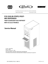
COVER
WATER PUMP MOTOR
(ELECTRICAL CONNECTIONS)
CARBONATED
WATER TANK
RELIEF
VALVE
LIQUID DUAL CHECK
VALVE
OR
VENTED DUAL–CHECK
VALVE
SAFETY THERMOSTAT
RETAINING SCREWS (2)
WATER PUMP
FIGURE 3. CARBONATOR ASSEMBLY COMPONENTS
WARNING: The Unit must be electrically grounded to avoid possible fatal electrical shock
or serious injury to the operator. The Unit power cord is equipped with a three-prong plug.
If a three-hole (grounded) electrical outlet is not available, use an approved method to
ground the Unit.

11 318511001
6. Connect 115 VAC, 60 Hz or 220–240 VAC, 50 Hz electrical power from the disconnect switch (not fur-
nished) fused at 15-amps (slow-blow) to the Unit with No. 16 AWG wire in suitable conduit or BX sheath.
Install power source green or green/yellow wire under the ground terminal lug located inside control box as
shown. Connect black or brown power cord wire with wire nut and white or blue wire under nut on motor
terminal. All WIRING MUST CONFORM TO NATIONAL AND LOCAL ELECTRICAL CODES.
7. Install motor wiring compartment cover and secure the two cover screws.
8. Install cabinet cover and secure with two screws.
PREPARATION FOR OPERATION
ADJUSTING CARBONATOR CO
2
REGULATOR AND TURN PLAIN WATER INLET LINE
ON
CAUTION: Before connecting the CO
2
regulator assembly to the CO
2
cylinder, turn the
regulator adjusting screw to the left (counterclockwise) until all tension is relieved from the
adjusting screw spring.
1. Open (counterclockwise) CO
2
cylinder valve slightly to allow the lines to slowly fill with CO
2
gas, then open
the valve fully to back-seat the valve. (Back-seating the valve prevents leakage around the valve shaft).
2. Adjust the carbonator CO
2
regulator to a nominal 80-psi.
3. Open one of the Post-Mix Dispenser dispensing valves to exhaust trapped air inside the carbonator tank.
CAUTION: Never operate the carbonator with the plain water inlet line shutoff valve closed.
‘‘Dry running” the water pump will burn out the pump. A pump damaged in this manner is
not covered by warranty.
4. Open the plain water inlet line shutoff valve.
UNIT OPERATION
NOTE: The carbonator tank liquid levels (pump cut-in and cut-out) were adjusted at the factory and
should require no further adjustment. If carbonator tank relief valve opens before the water pump mo-
tor cycles off, adjust carbonator tank liquid levels as instructed in Service Manual (P/N 318511004).
WARNING: The Unit must be electrically grounded to avoid possible fatal electrical shock
or serious injury to the operator. The Unit power cord is equipped with a three-prong plug.
If a three-hole (grounded) electrical outlet is not available, use an approved method to
ground the Unit.
1. Connect electrical power to the Unit. Water pump will start and fill the carbonated water tank with carbon-
ated water. Water pump will stop when tank is full.
WARNING: CO
2
Displaces Oxygen. Strict Attention must be observed in the prevention of
CO
2
(carbon dioxide) gas leaks in the entire CO
2
and soft drink system. If a CO
2
gas leak is
suspected, particularly in a small area, immediately ventilate the contaminated area before
attempting to repair the leak. Personnel exposed to high concentration of CO
2
gas will experience
tremors which are followed rapidly by loss of consciousness and suffocation.

12
318511001
WARNING: Disconnect electrical power to the carbonator to prevent personal injury before
attempting any internal maintenance. Only qualified personnel should service internal
components or electrical wiring.
2. Check for CO
2
, carbonated water, and plain water leaks and if evident, tighten any loose connections.
CAUTION: To prevent a fire hazard, no object should be placed or stored on top of the Unit.

13 318511001
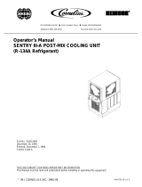
SAFETY THERMOSTAT
WATER PUMP
POWER CORD
LEVEL CONTROL
SWITCH (2)
FIGURE 4. WIRING DIAGRAM (MODEL NO. 416411000, 1621, AND 496411000)
WATER PUMP
POWER CORD
LEVEL CONTROL
SWITCH (2)
FIGURE 5. WIRING DIAGRAM (MODEL NO. 496411020)

14
318511001
WATER PUMP
POWER CORD
LEVEL CONTROL
SWITCH (2)
FIGURE 6. WIRING DIAGRAM (MODEL NO. 496411040)

15 318511001
TROUBLESHOOTING
WARNING: Disconnect electrical power to the carbonator to prevent personal injury before
attempting any internal maintenance. Only qualified personnel should service the internal
components or the electrical wiring.
If repairs to the carbonated water or the plain water systems must be made, disconnect electrical
power to the Unit, then shut off CO
2
and plain water sources. Dispense from dispensing valve until
carbonator tank CO
2
pressure has been relieved.
Trouble Probable Cause Remedy
WATER PUMP MOTOR WILL
NOT OPERATE.
A. Power cord unplugged or
circuit breaker open in panel
box.
A. Plug in power cord or reset circuit
breaker.
B. Inoperative water pump motor. B. Replace water pump motor as
instructed.
C. Dirty balance mechanism. C. Clean balance mechanism.
D. Loose connections and/or
open electrical circuit.
D. Tighten connections and/or repair
open circuit. Check line voltage.
E. Overheated motor cut off by
thermal overload protector.
E. Check for proper line voltage.
Check for restricted pump
discharge.
F. Inoperative level control
switches.
F. Replace level control switches as
instructed.
G. Binding or damaged balance
mechanism.
G. Repair or replace balance
mechanism.
H. Water pump binding (new or
replacement pumps only).
H. Remove water pump from motor,
rotate pump or motor shaft 180
degrees, then recouple pump to
motor.
I. Water pump damaged. I. Replace water pump as
instructed.
J. Safety thermostat inoperative
(Models 416411000 and
1621).
J. Replace safety thermostat as
instructed.
K. Water pressure low or
pressure switch inoperative
(Model 496411020 only)
K. Restore water pressure or
replace pressure switch.
WATER PUMP MOTOR WILL
NOT SHUT OFF.
A. Foreign object restricting tank
movement.
A. Remove foreign object.
B. Dirty balance mechanism. B. Clean balance mechanism.
C. Leak in carbonated water line. C. Tighten or replace line.
D. Inoperative level control
switches.
D. Replace level control switches as
instructed.
E. Binding or damaged balance
mechanism.
E. Repair or replace balance
mechanism.

16
318511001
Trouble RemedyProbable Cause
ERRATIC CYCLING OF
CARBONATOR.
A. Balance mechanism spring
obstructed or ‘‘cocked’’.
A. Remove obstruction. Make sure
spring is perpendicular to spring
release and is not twisted.
B. Dirty balance mechanism. B. Clean balance mechanism.
WATER PUMP MOTOR
OPERATES BUT WATER
PUMP DOES NOT PUMP
WATER.
A. Water pump inlet water
strainer screen dirty.
A. Clean or replace water strainer
screen as instructed.
B. Kinked water supply line. B. Straighten water supply line.
C. Restriction between water
pump outlet and carbonator
tank inlet.
C. Remove restriction.
D. Foreign object in water pump
bypass.
D. Clean. (Note: Count number of
turns bypass screw makes when
removing and install same
number of turns.)
E. Water pump worn out. E. Replace water pump as
instructed.
WATER PUMP CAPACITY
TOO LOW.
A. Water pump inlet water
strainer screen dirty.
A. Clean or replace water strainer
screen as instructed.
B. Water supply capacity too low. B. Inlet water supply must be at a
minimum of 100-gallons per hour
with a maximum water pressure
of 70-psi.
C. Water filter clogged. C. Replace water filter.
D. Inoperative water pump. D. Replace water pump as
instructed.

17 318511001
WARRANTY
IMI Cornelius Inc. warrants that all equipment and parts are free from defects in material and workmanship un-
der normal use and service. For a copy of the warranty applicable to your Cornelius, Remcor or Wilshire prod-
uct, in your country, please write, fax or telephone the IMI Cornelius office nearest you. Please provide the
equipment model number, serial number and the date of purchase.
IMI Cornelius Offices
AUSTRALIA D P. O . 210, D RIVERWOOD, D NSW 2210, AUSTRALIA D (61) 2 533 3122 D FAX (61) 2 534 2166
AUSTRIA
D AM LANGEN FELDE 32 D A-1222 D VIENNA, AUSTRIA D (43) 1 233 520 D FAX (43) 1-2335-2930
BELGIUM
D BOSKAPELLEI 122 D B-2930 BRAASCHAAT, BELGIUM D (32) 3 664 0552 D FAX (32) 3 665 2307
BRAZIL
D RUA ITAOCARA 97 D TOMAS COELHO D RIO DE JANEIRO, BRAZIL D (55) 21 591 7150 D FAX (55) 21 593 1829
ENGLAND
D TYTHING ROAD ALCESTER D WARWICKSHIRE, B49 6 EU, ENGLAND D (44) 789 763 101 D FAX (44) 789 763 644
FRANCE
D 71 ROUTE DE ST. DENIS D F-95170 DEUIL LA BARRE D PAR IS, FRANCE D (33) 1 34 28 6200 D FAX (33) 1 34 28 6201
GERMANY
D CARL LEVERKUS STRASSE 15 D D-4018 LANGENFELD, GERMANY D (49) 2173 7930 D FAX (49) 2173 77 438
GREECE
D 488 MESSOGION AVENUE D AGIA PARASKEVI D 153 42 D ATHENS, GREECE D (30) 1 600 1073 D FAX (30) 1 601 2491
HONG
KONG D 1104 TAIKOTSUI CENTRE D 11-15 KOK CHEUNG ST D TAIKOKTSUE, HONG KONG D (852) 789 9882 D FAX (852) 391 6222
ITALY
D VIA PELLIZZARI 11 D 1-20059 D VIMARCATE, ITALY D (39) 39 608 0817 D FAX (39) 39 608 0814
NEW
ZEALAND D 20 LANSFORD CRES. D P. O . BOX 19-044 AVONDALE D AUCKLAND 7, NEW ZEALAND D (64) 9 8200 357 D FAX (64) 9 8200 361
SINGAPORE
D 16 TUAS STREET D SINGAPORE 2263 D (65) 862 5542 D FAX (65) 862 5604
SPAIN
D POLIGONO INDUSTRAIL D RIERA DEL FONOLLAR D E-08830 SANT BOI DE LLOBREGAT D BARCELONA, SPAIN D (34) 3 640 2839 D FAX (34) 3 654 3379
USA
D ONE CORNELIUS PLACE D ANOKA, MINNESOTA D (763) 421-6120 D FAX (763) 422-3255
LD004
4/21/98
/