Page is loading ...

Installation Manual
IMPORTANT:
TO THE INSTALLER.
It is the responsibility of
the Installer to ensure that
the water supply to the
dispensing equipment is
provided with protection
against backflow by an air
gap as defined in
ANSI/ASME A112.1.2-1979;
or an approved vacuum
breaker or other such
method as proved effective
by test.
Water pipe connections
and fixtures directly
connected to a potable
water supply shall be
sized, installed, and
maintained according to
Federal, State, and Local
Codes.
VANTAGE
PRE-MIX DISPENSER
Telephone (800) 238-3600 Facsimile (612) 422-3246
THIS DOCUMENT CONTAINS IMPORTANT INFORMATION
This Manual must be read and understood before installing or operating this equipment
CORNELIUS INC g One Cornelius Place g Anoka, MN 55303-6234
© CORNELIUS INC; 1997-2014
PRINTED IN U.S.A
Release Date: August 11, 1997
Publication Number: 560001790
Revision Date: May 07, 2014
Revision: B

TABLE OF CONTENTS
Page
SAFETY 1. . . . . . . . . . . . . . . . . . . . . . . . . . . . . . . . . . . . . . . . . . . . . . . . . . . . . . . . . . . . . . . . . .
SAFETY INFORMATION 1. . . . . . . . . . . . . . . . . . . . . . . . . . . . . . . . . . . . . . . . . . . . . .
RECOGNIZE SAFETY INFORMATION 1. . . . . . . . . . . . . . . . . . . . . . . . . . . . . . .
UNDERSTAND SIGNAL WORDS 1. . . . . . . . . . . . . . . . . . . . . . . . . . . . . . . . . . . .
FOLLOW SAFETY INSTRUCTIONS 1. . . . . . . . . . . . . . . . . . . . . . . . . . . . . . . . .
GENERAL INFORMATION 3. . . . . . . . . . . . . . . . . . . . . . . . . . . . . . . . . . . . . . . . . . . . . . . . . .
GENERAL DESCRIPTION 3. . . . . . . . . . . . . . . . . . . . . . . . . . . . . . . . . . . . . . . . . . . . . .
UNIT DESCRIPTION 3. . . . . . . . . . . . . . . . . . . . . . . . . . . . . . . . . . . . . . . . . . . . . . . . . . .
WARRANTY REFERENCE INFORMATION 3. . . . . . . . . . . . . . . . . . . . . . . . . . . . . . .
THEORY OF OPERATION 5. . . . . . . . . . . . . . . . . . . . . . . . . . . . . . . . . . . . . . . . . . . . . .
INSTALLATION 7. . . . . . . . . . . . . . . . . . . . . . . . . . . . . . . . . . . . . . . . . . . . . . . . . . . . . . . . . . . .
UNPACKING AND INSPECTION 7. . . . . . . . . . . . . . . . . . . . . . . . . . . . . . . . . . . . . . . .
IDENTIFICATION OF LOOSE-SHIPPED PARTS 7. . . . . . . . . . . . . . . . . . . . . . . . . . .
SELECTING LOCATION 7. . . . . . . . . . . . . . . . . . . . . . . . . . . . . . . . . . . . . . . . . . . . . . . .
INSTALLATION 8. . . . . . . . . . . . . . . . . . . . . . . . . . . . . . . . . . . . . . . . . . . . . . . . . . . . . . . .
INSTALLING UNIT ON COUNTERTOP 8. . . . . . . . . . . . . . . . . . . . . . . . . . . . . . .
FILL WATER TANK AND START REFRIGERATION SYSTEM 8. . . . . . . . . . .
ROUTING AND CONNECTING PRODUCT INLET LINES 9. . . . . . . . . . . . . .
INSTALLING DISPENSING VALVES KNOBS 9. . . . . . . . . . . . . . . . . . . . . . . . .
CONNECTING CO2 GAS LINES TO PRODUCT TANKS 9. . . . . . . . . . . . . . .
PREPARING UNIT FOR OPERATION 10. . . . . . . . . . . . . . . . . . . . . . . . . . . . . . . . . . . .
UNIT OPERATION 10. . . . . . . . . . . . . . . . . . . . . . . . . . . . . . . . . . . . . . . . . . . . . . . . . . . . .
OPERATOR’S INSTRUCTIONS 11. . . . . . . . . . . . . . . . . . . . . . . . . . . . . . . . . . . . . . . . . . . . .
OPERATING CONTROLS 11. . . . . . . . . . . . . . . . . . . . . . . . . . . . . . . . . . . . . . . . . . . . . .
DISPENSING VALVE 11. . . . . . . . . . . . . . . . . . . . . . . . . . . . . . . . . . . . . . . . . . . . . .
DAILY PRE-OPERATION CHECK 11. . . . . . . . . . . . . . . . . . . . . . . . . . . . . . . . . . . . . . . .
UNIT OPERATION 11. . . . . . . . . . . . . . . . . . . . . . . . . . . . . . . . . . . . . . . . . . . . . . . . . . . . .
ADJUSTMENTS 11. . . . . . . . . . . . . . . . . . . . . . . . . . . . . . . . . . . . . . . . . . . . . . . . . . . . . . .
PRODUCT TANK CO2 REGULATORS 11. . . . . . . . . . . . . . . . . . . . . . . . . . . . . . .
ADJUSTING DISPENSED PRODUCT FLOW RATE 11. . . . . . . . . . . . . . . . . . .
REPLENISHING CO2 SUPPLY 12. . . . . . . . . . . . . . . . . . . . . . . . . . . . . . . . . . . . . . . . . .
REPLENISHING PRODUCT SUPPLY 12. . . . . . . . . . . . . . . . . . . . . . . . . . . . . . . . . . . .
CLEANING AND SANITIZING 12. . . . . . . . . . . . . . . . . . . . . . . . . . . . . . . . . . . . . . . . . . .
DAILY CLEANING OF UNIT 12. . . . . . . . . . . . . . . . . . . . . . . . . . . . . . . . . . . . . . . .
SANITIZING UNIT 12. . . . . . . . . . . . . . . . . . . . . . . . . . . . . . . . . . . . . . . . . . . . . . . . .
CHECKING DROP-IN REFRIGERATION ASSEMBLY CONDENSER COIL
FOR RESTRICTIONS 12. . . . . . . . . . . . . . . . . . . . . . . . . . . . . . . . . . . . . . . . . . . . . . . . . .
CHECKING ICE WATER BATH 13. . . . . . . . . . . . . . . . . . . . . . . . . . . . . . . . . . . . . . . . . .
CLEANING CO2 GAS CHECK VALVES 13. . . . . . . . . . . . . . . . . . . . . . . . . . . . . . . . . .
SERVICE AND MAINTENANCE 15. . . . . . . . . . . . . . . . . . . . . . . . . . . . . . . . . . . . . . . . . . . . .
PREPARING UNIT FOR SHIPPING OR RELOCATING 15. . . . . . . . . . . . . . . . . . . . .
HOOD, FRONT ACCESS PANEL AND DRIP TRAY REMOVAL 15. . . . . . . . . . . . . .
HOOD REMOVAL 15. . . . . . . . . . . . . . . . . . . . . . . . . . . . . . . . . . . . . . . . . . . . . . . . .

TABLE OF CONTENTS (cont’d)
Page
FRONT ACCESS PANEL REMOVAL 15. . . . . . . . . . . . . . . . . . . . . . . . . . . . . . . . .
DRIP TRAY REMOVAL 17. . . . . . . . . . . . . . . . . . . . . . . . . . . . . . . . . . . . . . . . . . . . .
PERIODIC INSPECTION 17. . . . . . . . . . . . . . . . . . . . . . . . . . . . . . . . . . . . . . . . . . . . . . .
ADJUSTMENTS 17.......................................................
ADJUSTING PRODUCT TANKS CO2 REGULATORS 17. . . . . . . . . . . . . . . . . .
ADJUSTING DISPENSED PRODUCT FLOW RATE 17...................
CLEANING AND SANITIZING 17. . . . . . . . . . . . . . . . . . . . . . . . . . . . . . . . . . . . . . . . . . .
DAILY CLEANING OF UNIT EXTERIOR 17. . . . . . . . . . . . . . . . . . . . . . . . . . . . . .
WEEKLY CLEANING OF DISPENSING VALVES 18. . . . . . . . . . . . . . . . . . . . . .
SANITIZING UNIT 18. . . . . . . . . . . . . . . . . . . . . . . . . . . . . . . . . . . . . . . . . . . . . . . . .
CLEANING DROP-IN REFRIGERATION ASSEMBLY CONDENSER COIL 20. . . .
CHECKING ICE WATER BATH 20. . . . . . . . . . . . . . . . . . . . . . . . . . . . . . . . . . . . . . . . . .
CLEANING WATER TANK 20. . . . . . . . . . . . . . . . . . . . . . . . . . . . . . . . . . . . . . . . . . . . . .
REPLENISHING CO2 SUPPLY 21. . . . . . . . . . . . . . . . . . . . . . . . . . . . . . . . . . . . . . . . . .
REPLENISHING PRODUCT SUPPLY 22. . . . . . . . . . . . . . . . . . . . . . . . . . . . . . . . . . . .
PRODUCT FLAVOR CHANGE 22. . . . . . . . . . . . . . . . . . . . . . . . . . . . . . . . . . . . . . . . . .
CLEANING CO2 SYSTEM CO2 GAS CHECK VALVES 22. . . . . . . . . . . . . . . . . . . . .
TROUBLESHOOTING 25. . . . . . . . . . . . . . . . . . . . . . . . . . . . . . . . . . . . . . . . . . . . . . . . . . . . . .
TROUBLESHOOTING DISPENSING SYSTEM 25. . . . . . . . . . . . . . . . . . . . . . . . . . . .
NO PRODUCT DISPENSED. 25. . . . . . . . . . . . . . . . . . . . . . . . . . . . . . . . . . . . . . .
DISPENSED PRODUCT COMES OUT OF DISPENS- ING VALVE CLEAR
BUT FOAMS IN CUP. 25. . . . . . . . . . . . . . . . . . . . . . . . . . . . . . . . . . . . . . . . . . . . . .
DISPENSED PRODUCT FOAMS AS IT LEAVES DISPENSING VALVE. 25. .
TROUBLESHOOTING REFRIGERATION SYSTEM 26. . . . . . . . . . . . . . . . . . . . . . . .
COMPRESSOR DOES NOT OPERATE. 26. . . . . . . . . . . . . . . . . . . . . . . . . . . . .
COMPRESSOR OPERATES CONTINUOUSLY BUT DOES NOT FORM
SUFFICIENT ICE BANK. 26. . . . . . . . . . . . . . . . . . . . . . . . . . . . . . . . . . . . . . . . . . .
CONDENSER FAN MOTOR NOT OPERATING. 26. . . . . . . . . . . . . . . . . . . . . . .
AGITATOR MOTOR NOT OPERATING. 26. . . . . . . . . . . . . . . . . . . . . . . . . . . . . .
LIST OF FIGURES
FIGURE 1. VANTAGE FIVE-FLAVOR PRE-MIX DISPENSER SHOWN 3. . . . . . .
FIGURE 2. FLOW DIAGRAM (FIVE-FLAVOR UNIT SHOWN) 6. . . . . . . . . . . . . . .
FIGURE 3. UNIT PRODUCT INLET CONNECTIONS 9. . . . . . . . . . . . . . . . . . . . . . .
FIGURE 4. PARTS IDENTIFICATION (FIVE-FLAVOR UNIT SHOWN) 16. . . . . . . .
FIGURE 5. DISPENSING VALVE PARTS IDENTIFICATION 19. . . . . . . . . . . . . . . . .
FIGURE 6. CO2 GAS CHECK VALVE 22. . . . . . . . . . . . . . . . . . . . . . . . . . . . . . . . . . . .
FIGURE 7. WIRING DIAGRAM 23. . . . . . . . . . . . . . . . . . . . . . . . . . . . . . . . . . . . . . . . . .
LIST OF TABLES
TABLE 1. DESIGN DATA 4. . . . . . . . . . . . . . . . . . . . . . . . . . . . . . . . . . . . . . . . . . . . . . .
TABLE 2. LOOSE-SHIPPED PARTS 7. . . . . . . . . . . . . . . . . . . . . . . . . . . . . . . . . . . . .

1
SAFETY
SAFETY INFORMATION
Recognize Safety Information
This is the safety-alert symbol. When you see this
symbol on our machine or in this manual, be alert to
the potentional for personal injury.
Follow recommended precautions and safe operating
practices.
DANGER
Understand Signal Words
A signal word - DANGER, WARNING, OR CAUTION
is used with the safety-alert symbol. DANGER identi-
fies the most serious hazards.
Safety signs with signal word DANGER or WARNING
are typically near specific hazards.
WARNING
General precautions are listed on CAUTION safety
signs. CAUTION also calls attention to safety mes-
sages in this manual.
CAUTION
Follow Safety Instructions
Carefully read all safety messages in this manual and on your machine safety signs.
Keep safety signs in good condition. Replace missing or damaged safety signs.
Learn how to operate the machine and how to use the controls properly. Do not let
anyone operate the machine without instructions. Keep your machine in proper work-
ing condition. Unauthorized modifications to the machine may impair function and/or
safety and affect the machine life.
Warranty Registration Date
(to be filled out by customer)
Unit Part Number:
Serial Number:
Install Date:
Local Authorized
Service Center:
Claims: In the event of shortage, notify the carrier as well as Cornelius immediately. In the event of dam-
age, notify the carrier. Cornelius is not responsible for damage occurring in transit, but will gladly
render assistance necessary to pursue your claim. Merchandise must be inspected for concealed
damage within 15 days of receipt.

2
THIS PAGE LEFT BLANK INTENTIONALLY

3
GENERAL INFORMATION
IMPORTANT: To the user of this manual -- This manual is a guide for installing, operating, and
maintaining this equipment. Refer to Table of Contents for page location of detailed information
pertaining to questions that arise during installation, operation, service and maintenance, or
troubleshooting this equipment.
This Unit contains no User serviceable parts and must be installed and serviced by a qualified Service Person.
GENERAL DESCRIPTION
This section gives the Unit description, theory of operation, and design data for the four and five-flavor Vantage
Pre-Mix Dispensers hereafter referred to as Units.
UNIT DESCRIPTION
The Units are compact with stainless-steel lower housings. The Units may be island-mounted or installed on
front or rear countertop. These Units are equipped with drop-in type 1/3 H.P. refrigeration assemblies and are
removable for service and maintenance.
Installation of Unit on countertop, installation of LOOSE-SHIPPED PARTS, filling water tank with water,
connection of Unit to product tanks with regulated CO
2
pressure, and connection of Unit to electrical outlet with
proper electrical requirements is all that is required to set Unit up for operation.
CAUTION: Before shipping, storing, or relocating this Unit, the product systems must be
sanitized and all sanitizing solution must be purged from the product systems with potable
water. A freezing ambient environment will cause residual water remaining inside the Unit
to freeze resulting in damage to the internal components.
WARRANTY REFERENCE INFORMATION
Warranty Registration Date
(to be filled out by customer)
Unit Part Number:
Serial Number:
Install Date:
Local Authorized
Service Center:
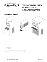
FIGURE 1. VANTAGE FIVE-FLAVOR PRE-MIX DISPENSER SHOWN

4
Table 1. Design Data
Unit Part Numbers:
60 Hz Units
Four-Flavor 120 VAC, 60 Hz 281604XXX
Five-Flavor 120 VAC, 60 Hz 281605XXX
Four-Flavor 230 VAC, 60 Hz 481604XXX
Five-Flavor 230 VAC, 60 Hz 481605XXX
50 Hz Units (CE Units)
Four-Flavor 230 VAC, 50 Hz 481704XXX
Five-Flavor 230 VAC, 50 Hz 481705XXX
Overall Dimensions:
Width 15-inches
Height 18-1/2 inches
Depth (with drip tray in place on Unit) 26-inches
Weight (approximate):
Shipping (one carton) 90 pounds
Dry Weight (approximate) 88 pounds
Ice Bank Weight (approximate) 12 pounds
Drop-In Refrigeration Assembly 48 pounds
Water Bath Capacity (no ice bank) 5.75 gallons
Dispensing Rate: (approximate)
No. of
Valves
No. of 6-oz.
Drinks/Min
*No. of drinks
38° F or below
(minimum)
4 4 100
5 4 100
*Number of 6-oz. drinks dispensed 38° F or below @ 75° F product inlet temperature and 75° F ambient.
Refrigeration Requirement:
Refrigerant See Unit Nameplate
Ambient Operating Temperature 50° F to 105° F
Electrical Requirements:
Operating Voltage See Unit Nameplate
Current Draw See Unit Nameplate

5
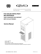
THEORY OF OPERATION
(see Figure 2)
A CO
2
cylinder delivers carbon dioxide (CO
2
) gas through adjustable CO
2
regulators to the product tanks. When
dispensing valve is opened, CO
2
pressure exerted upon product tank contents pushes product from the product
tank, through the Unit cooling coil, and on to the dispensing valve resulting in a dispensed drink.
When Unit power cord is plugged into an electrical outlet, the compressor, condenser fan motor, and agitator
motor will start and begin forming an ice bank in the water tank. When full ice bank has been formed,
compressor and condenser fan motor will stop but agitator motor will continue to operate circulating ice water in
water tank. The water tank ice bank control will cycle compressor and condenser fan motor on and off as
required to maintain a full ice bank.
WARNING: CO
2
displaces oxygen. Strict attention must be observed in the prevention of
CO
2
(carbon dioxide) gas leaks in the entire CO
2
and soft drink system. If a CO
2
gas leak is
suspected, particularly in a small area, immediately ventilate the contaminated area before
attempting to repair the leak. Personnel exposed to high concentration of CO
2
gas will experience
tremors which are followed rapidly by loss of consciousness and suffocation.

6
FIGURE 2. FLOW DIAGRAM (FIVE-FLAVOR UNIT SHOWN)

7
INSTALLATION
This section covers unpacking and inspection, identification of LOOSE-SHIPPED PARTS, selecting location,
installing Unit, preparing Unit for operation, and Unit operation.
UNPACKING AND INSPECTION
(see Figure 4)
1. After Unit has been unpacked, remove shipping tape and other packing material.
2. Remove hood by loosening screw on top of hood until screw disengages from drop-in refrigeration
assembly, then lift hood up off Unit.
3. Unpack LOOSE-SHIPPED PARTS. Make sure all items are present and in good condition.
Table 2. Loose-Shipped Parts
Item
No. Part No. Name
Qty.
4-fl 5-fl
1 4537 Drip Tray 1 1
2 4547 Cup Rest 1 1
3 317904XXX Flavor Decal Kit 1 1
4 151741039 Knob, Dispensing Valve 4 5
IDENTIFICATION OF LOOSE-SHIPPED PARTS
(see Figure 4)
1. DRIP TRAY (item 1) to be installed on the Unit, then CUP REST (item 2) to be installed in the drip tray.
2. Individual flavor decals included in the FLAVOR DECAL KIT (item 3) are to be installed on the
DISPENSING VALVES KNOBS (item 4), then knobs are to be installed on the dispensing valves .
SELECTING LOCATION
DANGER: To avoid possible fatal electrical shock or serious injury to the operator, it is
highly recommended that a GFCI (ground fault circuit interrupt) be installed in the
electrical circuit for the domestic Units. It is required that an ELCB (earth leakage circuit
breaker) be installed in the electrical circuit for the export Units
This Unit may be island-mounted or installed on a front or rear counter. Locate the Unit so the following
requirements are satisfied.
1. The Unit must be installed near a properly grounded electrical outlet with proper electrical requirements.
The electrical circuit should be fused at 20-amps (“slow-blow”) or circuit must be connected through an
equivalent HACR circuit breaker.The electrical outlet must be accessible for ease of connecting and
disconnecting the Unit power cord from the outlet. No other electrical equipment should be connected to
this circuit. ALL ELECTRICAL WIRING MUST CONFORM TO NATIONAL AND LOCAL ELECTRICAL
CODES.
NOTE: The Unit was thoroughly inspected before leaving the factory and the carrier has accepted and
signed for it. Any damage or irregularities should be noted at time of delivery (or not later than 15 days
from date of delivery) and immediately reported to the delivering carrier. Request a written inspection
report from Claims Inspector to substantiate any necessary claim. File claim with the delivering carrier,
not with Cornelius Inc.

8
CAUTION: Do not place or store anything on top of the Unit.
2. Locate the Unit to provide the following clearances--A minimum of 18-inches clearance must be maintained
above the Unit to the nearest obstruction (shelf, cupboard, ceiling, etc.). A minimum clearance of 12-inches
must be maintained on the back side and 6-inches clearance on both sides of the Unit to allow for proper
air flow through the Unit. The Unit must be located close to a permanent drain if a drip tray drain hose will
be connected to the drip tray.
INSTALLATION
INSTALLING UNIT ON COUNTERTOP
The product inlet supply lines, Unit power cord, water tank drain hose, and drip tray drain hose (if used) may be
either routed through hole cut in the countertop under the Unit or over back edge of the countertop behind the
Unit. Proceed as follows to install the Unit.
1. Place Unit in position on the countertop.
2. To comply with National Sanitation Foundation (NSF) requirements, Unit base must be sealed to the
countertop and all access holes to inside of the Unit base must be closed and sealed.
NOTE: An alternate arrangement to avoid sealing Unit base to countertop as described would be to
install the optional Leg Kit (4923).
A. Tilt Unit up to expose bottom of base.
B. Liberally apply a silastic sealant such as Dow Corning RTV 731 or equivalent on base bottom edges.
NOTE: Do not move Unit after positioning or seal from Unit base to countertop will be broken.
C. Lower Unit into operating position on countertop to complete seal from Unit base to countertop.
D. Apply additional sealant around bottom of Unit base. Seal must have a minimum radius of 1/2-inch to
prevent crevices and to insure a complete seal.
FILL WATER TANK AND START REFRIGERATION SYSTEM
(see Figure 4)
NOTE: Use low-mineral-content water where a local water problem exists.
1. Remove the Unit front access panel, then make sure plug in water tank drain hose located behind the
panel is securely in place.
2. Lift insulation pad covering front section of the water tank.
3. Fill water tank with clean water until water runs out of the water tank overflow tube which will empty into the
drip tray. USE LOW-MINERAL-CONTENT WATER WHERE A LOCAL WATER PROBLEM EXIST.
4. Replace insulation pad over front section of the water tank.
WARNING: The Unit must be electrically grounded to avoid possible fatal electrical shock
or serious injury to the operator. The Unit power cord is equipped with a three-prong plug.
If a three-hole (grounded) electrical outlet is not available, use an approved method to
ground the Unit.
5. Plug Unit power cord into a properly grounded electrical outlet. The refrigeration system will start after a
2-second time delay.

9
ROUTING AND CONNECTING PRODUCT INLET LINES
(see Figures 2, 3, and 4)
1. Route product inlet lines (numbered for identification) up over edge of the countertop behind the Unit or up
through hole cut in the countertop underneath the Unit. Route product inlet lines up to a point behind the
Unit front access panel close to the barbed product inlet connections on the Unit.
NOTE: The Unit barbed product inlet lines connections to the dispensing valves are labeled to identify
the dispensing valve they serve. For example: the line labeled ‘ ‘1’’ must be connected to system that
provides product to be dispensed from NO.1 dispensing valve. (NO. 1 dispensing valve is the valve on
right side when facing front of Unit.)
IMPORTANT
TO THE INSTALLER: DO NOT CUT CLAMPS SECURING
BARBED FITTINGS ON ENDS OF THE UNIT PRODUCT
INLET CONNECTIONS.
FIGURE 3. UNIT PRODUCT INLET CONNECTIONS
2. Connect product inlet lines to the barbed product inlet connections on the Unit. Secure connections with
tubing clamps.
3. All access holes to inside of the Unit base must be closed and sealed.
INSTALLING DISPENSING VALVES KNOBS
(see Figure 4)
1. Install dispensing valves knobs (LOOSE-SHIPPED with the Unit) on the dispensing valves.
CONNECTING CO
2
GAS LINES TO PRODUCT TANKS
(see Figure 2)
WARNING: CO
2
displaces oxygen. Strict attention must be observed in the prevention of
CO
2
(carbon dioxide) gas leaks in the entire CO
2
and soft drink system. If a CO
2
gas leak is
suspected, particularly in a small area, immediately ventilate the contaminated area before
attempting to repair the leak. Personnel exposed to high concentration of CO
2
gas will experience
tremors which are followed rapidly by loss of consciousness and suffocation.
WARNING: To avoid personal injury and/or property damage, always secure CO
2
cylinder in
upright position with a safety chain to prevent it from falling over. Should valve become
accidentally damaged or broken off, CO
2
cylinder can cause serious personal injury.
1. Position CO
2
cylinder in upright position and secure with safety chain.

10
2. Install primary CO
2
regulator on CO
2
cylinder. MAKE SURE NYLON WASHER IS INSIDE REGULATOR
ASSEMBLY COUPLING NUT BEFORE CONNECTING TO CYLINDER.
3. Connect CO
2
lines, with quick disconnects on their ends (not provided), to primary CO
2
regulator
assembly. DO NOT CONNECT CO
2
LINES TO PRODUCT TANKS AT THIS TIME.
PREPARING UNIT FOR OPERATION
CAUTION: Before opening CO
2
cylinder shutoff valve, turn primary CO
2
regulators
adjusting screws to the left (counterclockwise) until all tension is relieved from adjusting
screws springs.
1. Open (counterclockwise) CO
2
cylinder shutoff valve slightly to allow lines to slowly fill with gas, then open
valve fully to back-seat valve. (Back-seating valve prevents leakage around valve shaft.)
2. Adjust product tanks primary CO
2
regulators pressure settings as instructed in SERVICE AND
MAINTENANCE section of this manual..
3. Connect CO
2
and product lines to product tanks. Check for leaks and tighten loose connections.
UNIT OPERATION
1. Dispense from each dispensing valve until air is purged from systems and product is dispensed.
2. Check for leaks and tighten loose connections.
3. Adjust dispensing valves for dispensed product flow rate as instructed in SERVICE AND MAINTENANCE
section of this manual.
4. Install Unit front access panel and secure with screws.
5. Install hood on Unit and secure with screw. MAKE SURE HOOD GRILLE IS POSITIONED OVER THE
REFRIGERATION CONDENSER COIL WHEN HOOD IS IN PLACE ON THE UNIT.
6. Install drip tray on the Unit, then install cup rest in the drip tray.

11
OPERATOR’S INSTRUCTIONS
This section covers operators instructions for operating controls, daily pre-operation check, adjustments,
replenishing CO
2
and product supplies, cleaning and sanitizing, checking drop-in refrigeration assembly
condenser coil for restrictions, and checking ice water bath.
WARNING: Disconnect electrical power to Unit to prevent personal injury before attempting
any internal maintenance. Only qualified personnel should service internal components or
electrical wiring.
CAUTION: Do not place or store anything on top of the Unit.
IMPORTANT: Only qualified personnel should service the internal components or electrical wiring.
OPERATING CONTROLS
(see Figure 4)
DISPENSING VALVE
Place cup under dispensing valve nozzle. Pull dispensing valve knob forward until cup is full, of product then
release knob.
DAILY PRE-OPERATION CHECK
7. Make sure primary CO
2
regulator assembly 1800-psi gage indicator is not in shaded (‘‘change CO
2
cylinder’’) portion of dial. If so, CO
2
cylinder is almost empty and must be replaced as instructed in
SERVICE AND MAINTENANCE section of this manual.
8. Sufficient product supply in all product tanks. If not, replenish product supply as instructed in SERVICE
AND MAINTENANCE section of this manual.
9. Make sure drip tray is clean and clean cup rest is in place in drip tray.
UNIT OPERATION
Place cup or glass under dispensing valve. Pull dispensing valve knob forward until cup or glass is full of
product, then release the knob.
ADJUSTMENTS
PRODUCT TANK CO
2
REGULATORS
Product tank CO
2
regulators should be periodically checked for proper pressure settings and if necessary,
adjusted as instructed in SERVICE AND MAINTENANCE section of this manual.
ADJUSTING DISPENSED PRODUCT FLOW RATE
Product flow rate of dispensed product should be periodically checked and if necessary, adjusted as instructed
in SERVICE AND MAINTENANCE section of this manual.

12
REPLENISHING CO
2
SUPPLY
WARNING: CO
2
displaces oxygen. Strict attention must be observed in the prevention of
CO
2
(carbon dioxide) gas leaks in the entire CO
2
and soft drink system. If a CO
2
gas leak is
suspected, particularly in a small area, immediately ventilate the contaminated area before
attempting to repair the leak. Personnel exposed to high concentration of CO
2
gas will experience
tremors which are followed rapidly by loss of consciousness and suffocation.
NOTE: When indicator on primary CO
2
cylinder regulator assembly 1800-psi gage is in shaded
(‘‘change CO
2
cylinder’’) portion of the dial, CO
2
cylinder is almost empty and should be changed.
CO
2
supply should be checked daily and if necessary, replenished as instructed in SERVICE AND
MAINTENANCE section of this manual.
REPLENISHING PRODUCT SUPPLY
Product supply should be checked daily and if necessary, replenished as instructed in SERVICE AND
MAINTENANCE section of this manual.
CLEANING AND SANITIZING
DAILY CLEANING OF Unit
Daily cleaning of Unit should be performed at end of daily operation as instructed in SERVICE AND
MAINTENANCE section of this manual.
SANITIZING UNIT
The product systems should be sanitized as instructed every 90-days as instructed in SERVICE AND
MAINTENANCE section of this manual.The sanitizing procedure should be performed by a qualified Service
Person.
CHECKING DROP-IN REFRIGERATION ASSEMBLY CONDENSER COIL
FOR RESTRICTIONS
CAUTION: The refrigeration assembly condenser coil must be cleaned every 30-days.
Excessive accumulation of dust, lint, and grease on the condenser coil will restrict air flow
through the coil and cause the refrigeration system to overheat. Operating the refrigeration
system in an overheated condition will eventually lead to compressor failure and will automatically
void the factory warranty.
NOTE: Circulating air required to cool condenser coil is drawn in through grille on top of the hood and
is exhausted out through louvers on sides and back of the hood. Restricting air in and out of Unit will
decrease its cooling efficiency.
Area on top of Unit hood must be kept free of obstructions at all times. Make sure nothing is stored on top of
hood. Cooling Unit condenser coil should be periodically cleaned every 30-days as instructed in SERVICE AND
MAINTENANCE section of this manual.

13
CHECKING ICE WATER BATH
A ‘‘gurgle’’ heard from the Unit indicates water level in water tank is low and more water should be added as
instructed for maximum product cooling. Refer to SERVICE AND MAINTENANCE section of this manual.
CLEANING CO
2
GAS CHECK VALVES
(see Figure 2 and 6)
The CO
2
gas check valves must be inspected and serviced as instructed at least once a year under normal
conditions and after any CO
2
system servicing or disruption. Servicing of gas check valves should be performed
by qualified personnel. Refer to SERVICE AND MAINTENANCE section of this manual.

14
THIS PAGE LEFT BLANK INTENTIONALLY

SERVICE AND MAINTENANCE
This section describes the service and maintenance procedures to be performed on the Unit.
IMPORTANT: Only qualified personnel should service the internal components or electrical wiring.
DANGER: To avoid possible fatal electrical shock or serious injury to the operator, it is
highly recommended that a GFI (ground fault circuit interrupt) be installed in the electrical
circuit for the 60 Hz Units. It is required that an ELCB (earth leakage circuit breaker) be
installed in the electrical circuit for the 50 Hz Units.
WARNING: Disconnect electrical power from the Unit to prevent personal injury before
attempting any internal maintenance. Only qualified personnel should service the internal
components or electrical wiring.
PREPARING UNIT FOR SHIPPING OR RELOCATING
CAUTION: The Unit is intended for indoor installation only. Do not install this Unit in an
outdoor environment which would expose it to the outside elements.
CAUTION: Before shipping, storing, or relocating this Unit, the product systems must be
sanitized and all sanitizing solution must be purged from the product systems. A freezing
ambient environment will cause residual water remaining inside the Unit to freeze resulting
in damage to internal components.
HOOD, FRONT ACCESS PANEL AND DRIP TRAY REMOVAL
(see Figure 4)
HOOD REMOVAL
CAUTION: Do not place or store anything on top of the Unit.
Remove screw securing hood, then lift hood straight up off the Unit. Make sure grille on top of the hood is
positioned over the refrigeration condenser coil when re-installing the hood.
IMPORTANT: Circulating air, required to cool the refrigeration assembly condenser coil is drawn in
through grille on top of the hood and is exhausted out through louvers on sides and back of the Unit.
FRONT ACCESS PANEL REMOVAL
Remove two screws securing the front access panel, then remove the panel.
15

16
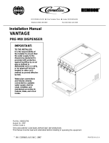
HOOD RETAINING
SCREW
HOOD
FRONT ACCESS
PANEL
FRONT ACCESS
PANEL RETAINING
SCREW (2)
DROP-IN
REFRIGERATION ASS’Y
WATER TANK
OVERFLOW TUBE
CONDENSER
COIL
AGITATOR
MOTOR
CONTROL
BOX
DISPENSING
VALVE (5)
PRODUCT INLET
TUBE (5)
WATER TANK
DRAIN HOSE
DRIP TRAY
CUP REST
INSULATION PAD
FIGURE 4. PARTS IDENTIFICATION (FIVE-FLAVOR UNIT SHOWN)

DRIP TRAY REMOVAL
CAUTION: Use extreme care when removing and installing the drip tray to prevent breaking
off plastic holding tabs on back of the tray.
Very carefully Lift drip tray up, then pull tray back to remove.
PERIODIC INSPECTION
1. Clean the drop-in refrigeration assembly condenser coil every 30-days as instructed. Cleaning the
condenser coil should be performed by a qualified Service Person. DO NOT place objects on top of the
hood or on back side of the Unit. Restricting circulating air in and out of the Unit will cause the refrigeration
system to overheat.
2. Check the dispensing valves for dripping that indicates leakage and repair as necessary.
ADJUSTMENTS
ADJUSTING PRODUCT TANKS CO
2
REGULATORS
WARNING: CO
2
displaces oxygen. Strict attention must be observed in the prevention of
CO
2
(carbon dioxide) gas leaks in the entire CO
2
and soft drink system. If a CO
2
gas leak is
suspected, particularly in a small area, immediately ventilate the contaminated area before
attempting to repair the leak. Personnel exposed to high concentration of CO
2
gas will experience
tremors which are followed rapidly by loss of consciousness and suffocation.
(see Figure 2)
Set product tanks CO
2
regulators, using Cornelius PRE-MIX COMPUTER slide rule or bottling room chart, at
equilibrium pressure for highest temperature encountered between product tank storage area and Unit plus
5-psig operating pressure for lines 10-feet in length or less and no vertical lift. Add one pound for every 10-feet
over initial 10-feet of product tank to Unit line length and one pound for every 2-feet of vertical lift. Add one
pound for every product tank on line over three tanks.
ADJUSTING DISPENSED PRODUCT FLOW RATE
(see Figure 5)
Rotate dispensing valve Compensator Adjusting Screw to the left (counterclockwise) for higher product flow rate
or to the right (clockwise) for lower product flow rate.
CLEANING AND SANITIZING
DAILY CLEANING OF UNIT EXTERIOR
1. Remove cup rest and drip tray from the Unit.
2. Wash cup rest and drip tray, then rinse them with warm water.
3. Re-install cup rest and drip tray on the Unit.
17
/