Page is loading ...

BUTTON AND LED LOCATIONS
TROUBLESHOOTING
WIRED INPUTS
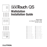
USING THIS GUIDE
OTHER QS LINK DEVICES
QS SENSOR MODULE (QSM) WITH WIRED OR WIRELESS INPUT DEVICES
Lutron Electronics Co., Inc. | 7200 Suter Road
Coopersburg, PA 18036-1299, U.S.A.
Help 1.800.523.9466 U.S.A., Canada and the Caribbean +1.888.235.2910 México +1.610.282.3800 Others
This guide is divided into sections. Each section deals with a particular feature or set of features
of the Energi Savr NodeTM unit and the equipment connected to it. Depending on the connected
equipment and the intended use of your Energi Savr NodeTM unit, some sections may not apply.
See below to determine which sections should be read.
0-10 V Outputs l Salidas l Sorties
4 X 50 mA
(Sinking O
nl
y l Rece
pcion
solam
en
te l Réc
epteur de
co
urant seulem
e
nt)
QSN-4T16-S-347
120-277 V~
50/60 Hz 500 mA
0-10 V / Softswitch
®
24/7 Help | Ayuda | Aide www.lutron.com
U.S.A. Canadá Caribbean | E.U.A. Caribe | É.-U., Caraïbes 1.800.523.9466
México +1.888.235.2910
Others | Otros | Autres +1.610.282.3800
Coopersburg, PA 18036, U.S.A.
500-14444 Rev. A
saving energy since 1961
Energi Savr Node
TM
Type 1
Enclosure
243C
LISTED
Ind.
Cont. Eq.
4 Softswit
ch
®
Circuits l Circuitos
Capacity l Capacidad l Capacité :
IE
C PELV / NEC
®
C
lass 2
Input Groups | Grupos de
entrada
Groupes d’entreés :
20
V
-
4
X 65 mA
QS Link | Elance | L
iaison :
24
V
-
4
62 mA
WARNING
Risk of Electric Shock. May Result in serious injury or death.
More than one disconnect may be required to de-energize
this device. Disconnect all power sources before servicing
unit.
ADVERTENCIA
Riesgo choque eléctrico. Puede resultar en lesiones graves o
muerte. Puede necesitarse más de una desconexión para
desenergizar este dispositivo. Desconecte todas las fuentes
de alimentación antes de prestar servicio a la unidad.
AVERTISSEMENT
Risque d'électrocution. Peut causer le décès de la personne
ou de graves lésions. Plus d’un débranchement peut être
Débrancher toutes les sources d’énergie avant de procéder
à l’entretien de cette unité.
®
4 x 16 A 120-277 V~
4 x 0,5 HP 120 V~
4 x 1,5 HP 277 V~
4 x 16 A 347 V~
All Energi Savr NodeTM units
Read:
»
Load Setup
Energi Savr NodeTM with Softswitch® unit
(QSN-4S16-S, QSN-4S16-S-347, QSN-4S20-S)
Energi Savr NodeTM for 0-10 V unit
(QSN-4T16-S, QSN-4T16-S-347, QSN-4T20-S)
Type 1
Enclosure
4 Softswitch
®
Circuits l C
irc
uit
os
Capacity l Capacidad l Capacité :
QSN-4S16-S-347
120-277 V
50/60 Hz 500 mA
Softswitch
®
Coopersburg, PA 18036, U.S.A.
500-14445 Rev. A
saving energy since 1961
Energi Savr Node
TM
WARNING
Risk of Electric Shock. May Result in serious injury or death.
More than one disconnect may be required to de-energize
this device. Disconnect all power sources before servicing
unit.
ADVERTENCIA
Riesgo choque eléctrico. Puede resultar en lesiones graves o
muerte. Puede necesitarse más de una desconexión para
desenergizar este dispositivo. Desconecte todas las fuentes
de alimentación antes de prestar servicio a la unidad.
AVERTISSEMENT
Risque d'électrocution. Peut causer le décès de la personne
ou de graves lésions. Plus d’un débranchement peut être
Débrancher toutes les sources d’énergie avant de procéder
à l’entretien de cette unité.
®
24/7 Help | Ayuda | Aide www.lutron.com
U.S.A. Canadá Caribbean | E.U.A. Caribe | É.-U., Caraïbes 1. 800.523.9466
México +1.888.235.2910
Others | Otros | Autres +1.610.282.3800
243C
LISTED
Ind.
Cont. Eq.
IE
C PE
L
V / NEC
®
Class 2
Input Groups | Gru
pos de entrada
Groupes d’entreés :
20
V
-
4
X 65 mA
QS Link | Elance | Liaison
:
24
V -
462 mA
4 x 16 A 120-277 V~
4 x 0,5 HP 120 V~
4 x 1,5 HP 277 V~
4 x 16 A 347 V~
LED Feedback
LED LED Behavior Description
Occ
(Occupancy Sensor)
Continuous On
Sensor detects Vacancy
1 flash per second
Sensor detects Occupancy
Off
Sensor never detected
Daylight
(Daylight Sensor )
Continuous On
Sensor is detected
Flashing
Sensor information transmitting on
the QS link
Off
Sensor never detected/sensor not
seeing light
IR
(Infrared Receiver)
Continuous On Receiver is detected
Flashing
IR button press detected
Off
Receiver never detected
Switch
(NEC
® Class2 Switch)
Continuous On
Switch detected/open
Flashing
Switch button press detected
Off
Switch never detected
CCI
(Contact Closure Input)
Continuous On
Contact detected/open
Flashing
Contact closed
Off
Contact never detected
Emerg
(Emergency Contact
Closure Input)
Continuous On
Normal operation/Contact Closed/
Jumpered
Rapid flash
Emergency Mode/Contact Open/
Jumper missing
QS Link
On/Flashing
/
Device transmitting/receiving on the
QS link
3 quick flashes every
4 seconds
Communication error
Off
Device not transmitting/receiving on
the QS link
Wired Continuous On
Wired sensor
Zone
Continuous On
Load is on
Off
Load is off
Troubleshooting using Symptoms
Symptom Cause Solution
Unable to add daylight
sensor to a zone
Existing daylight sensor
already assigned to the zone
Unassign the existing daylight sensor and
try again.
Unable to add an
occupancy sensor to
a zone
16 sensors have already
been assigned
No more than 16 sensors can be assigned
to one ESN unit. Unassign sensors until
below 16 sensor limit.
Daylight sensor fails to
turn on a zone
Occupancy sensor is
overriding the zone
Daylight sensors will not turn a zone on if
an occupancy sensor assigned to that zone
detects that the room is vacant.
Switched zone daylighting:
incorrect light level set during
Daylighting Setup
Reset the daylighting set point. See
Daylighting Setup.
When associating a
QSM to the Energi Savr
NodeTM unit, the ‘QSM’
LED flutters for 1
second, then turns off
A QSM has already been
associated to the Energi
Savr NodeTM unit.
To clear the QSM association and any
Energi Savr Node
TM unit zone assignments
to any QSM inputs, press and hold the
Input button on the Energi Savr NodeTM unit
for 10 seconds. The ‘Input’ LED will flutter
for 1 second, then turn off.
When associating a
wireless input device
to a QSM, the QSM
responds with 10 short
beeps
Maximum number of
associations to the QSM has
been exceeded for that
wireless input device type.
Unassign any unnecessary wireless inputs of
that device type and try again.
When associating a
wireless input device
to a QSM, the QSM
responds with 5 short
beeps
Input device is already
associated to another QSM
on the QS link.
If you choose to ignore the warning and try
to associate the same input device to the
QSM a second time, the input device will be
removed from association with the previous
QSM and will now be associated with the
new QSM. Note: This will also remove any
Energi Savr Node
TM
programming that the wireless device may
have had through the previous QSM.
QS Link LED quickly
flashes 3 times every 4
seconds
QS Link communication
error.
Check QS Link wiring
Technical Assistance
U.S.A. / Canada: 1.800.523.9466 Mexico: +1.888.235.2910 Other Countries: +1.610.282.3800
IMPORTANT NOTES
Energi Savr NodeTM with Softswitch® unit
(QSN-4S16-S, QSN-4S16-S-347, QSN-4S20-S)
Energi Savr NodeTM for 0-10 V unit
(QSN-4T16-S, QSN-4T16-S-347, QSN-4T20-S)
Energi Savr NodeT
manual programming guide
English
1. Manual Programming: This document describes manual
programming via the buttons on the front of the Energi Savr
NodeTM unit. For programming using the Apple iPod touch
or iPhone mobile digital devices, please see the Energi Savr
NodeTM app available from the Apple AppStore online store.
2. Use only compatible Lutron® sensors and controls.
032449 | Rev. C | 05/2014
24/7 Help
U.S.A., Canada and the Caribbean
1.800.523.9466
México
+1.888.235.2910
Others
+1.610.282.3800
Fax
+1.610.282.6311
w
w
w
.
l
u
t
r
o
n
.
c
o
m
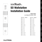
If you have wired sensor inputs wired directly to the Energi Savr NodeTM unit input group terminal
blocks, see below to determine which additional sections to read.
www.lutron.com
© 2014 Lutron Electronics Co., Inc.
P/N 032449 Rev. C 05/2014
Apple, iPhone, and iPod touch are trademarks of Apple Inc., registered in the U.S. and other countries.
AppStore is a service mark of Apple Inc.
Lutron, GRAFIK Eye, Pico, seeTouch, Softswitch and ) are registered trademarks, and Energi Savr
Node and Radio Powr Savr are trademarks of Lutron Electronics Co., Inc.
All Wired Inputs
Read:
»
Energi Savr NodeTM
(ESN) Unit Wired Input
Setup
OR
Energi
Savr
Node
TM
Unit
LUTRON
Dry Contact
Closure
Switch
Wires to “Switch”,
“CCI”, or “EMERG”
Input
»
Energi Savr
Node
TM (ESN)
Unit Wired
Input Setup
Wired
Occupancy
Sensor
Wires to “Occ” Input
Additional Sections:
»
Energi Savr NodeTM (ESN)
Unit Wired Input Setup
»
Occupancy Setup
Wired Wallstation
or Infrared (IR)
Sensor
Wires to “IR” Input
»
Energi Savr
NodeTM (ESN)
Unit Wired
Input Setup
Wired
Daylight
Sensor
Wires to “Daylight” Input
Additional Sections:
»
Energi Savr NodeTM (ESN)
Unit Wired Input Setup
»
Daylighting Setup
If you have a QSM wired to the Energi Savr NodeTM unit QS Link terminal block, read sections QS Sensor
Module (QSM) Input Setup and
QS Sensor Module (QSM) Zone Assignment. Some parts of the section
may not apply, depending on the devices connected to the QSM. See below to determine which additional sub-
sections to read for each type of connected device.
QSM Wireless Input Devices
Communicates with QSM via Radio Frequency (RF)
Read:
»
Subsection: Associating Wireless Input
Devices to a QSM
QS Sensor Module (QSM)
Wires to “QS Link” Terminal Block on
Energi Savr Node
TM unit
Wireless
Occupancy
Sensor
Additional Sections:
»
Occupancy Setup
»
Subsection: Assign Zones to
QSM Inputs
Wireless
Daylight
Sensor
Additional Sections:
»
Daylighting Setup
»
Subsection: Assign Zones to
QSM Inputs
Wired
Occupancy
Sensor
Additional Sections:
»
Occupancy Setup
»
Subsection: Assign Zones to
QSM Inputs
Wired
Daylight
Sensor
Additional Sections:
»
Daylighting Setup
»
Subsection: Assign Zones to
QSM Inputs
LUTRON
Pico®
Wireless
Controller
Additional Sections:
»
Subsection: Assign Zones to Pico®
Wireless Controller (through QSM)
QS Link
Wired Wallstation
or Infrared (IR)
Sensor
Additional Sections:
»
Subsection: Assign Zones
to QSM Inputs
OR
Energi
Savr
NodeTM
Unit
QS
Sensor
Module
Read:
»
QS Sensor Module (QSM)
Input Setup
»
QS Sensor Module (QSM)
Zone Assignment
QSM Wired Input Devices
Wires to Input Terminal Blocks on QSM
Read:
» Subsection: Associating Wired
Input Devices to a QSM
QS Link
If you have other devices wired to the Energi Savr NodeTM unit QS Link terminal block, see below to determine
which additional sections to read.
Energi
Savr
NodeTM
Unit
Wired
seeTouch® QS
Wallstation
Additional Sections:
» Wired seeTouch® QS Wallstations Programming
QSE-IO
Input/Output
Interface
Additional Sections:
» QSE-IO Input/Output Interface Programming
CCI1
CCI 2
CCI 3
CCI 4
COM
CCI 5
V
0-24 V 1 A
0-24 V ½ A
R
O
N
CCO 1 NC
CCO 1 NO
CCO 2 NC
CCO 2 NO
1-2 COM
CCO 3 NC
CCO 4 NO
CCO 3 NO
CCO 4 NC
3-4 COM
CCO 5 NC
5 COM
CCO 5 NO
V
R
MUX
COM
V+
MUX
500-13491 Rev. B
CCO 1
CCO 2
CCO 3
CCO 4
CCO 5
STAT
QS
800.523.9466
+1.610.282.3800
www.lutron.com/qs
QSE-IO
24 V 100 mA
®
243C IND. CONT. EQ.
0 2755761323 1
8 7 6 5 4 3 2 1
4 3 2 1
GRAFIK Eye® QS
Control Unit or
QS Timeclock
Additional Sections:
» GRAFIK Eye® QS Control Unit or QS Timeclock Programming
LUTRON
Zones
Inputs

PROGRAMMINGLEDs and BUTTON PRESSES
Lutron Electronics Co., Inc. | 7200 Suter Road
Coopersburg, PA 18036-1299, U.S.A.
Help 1.800.523.9466 U.S.A., Canada and the Caribbean +1.888.235.2910 México +1.610.282.3800 Others
1. Enter Load Setup. Simultaneously press and hold the Program and Input buttons for 3 seconds. LEDs for Group 1 Inputs and
‘Default’ will blink once per second.
2. Select options. Press the Option button to select the option and then use the and buttons for each zone to select the choice
for each option.
LED
Option Setting Choices
Opt 2 Load Type High LED 0-10 V Dimming (default)
1
Med LED 10-0 V Dimming
1
Low LED Switched
High LED and
Low LED
Receptacle
Opt 3
(not available on
QSN-4S16-S or
QSN-4S16-S-347)
High End Trim High-Med LEDs 100% maximum (default)
down to
55% minimum
Default + Opt 1
(not available on
QSN-4S16-S or
QSN-4S16-S-347)
Low End Trim Low-Med LEDs 0% minimum
up to
45% maximum
Default + Opt 2
Absolute
Minimum Light
Level
2
High-Med-Low LEDs 100% maximum
down to
0% minimum (default)
1
Not available on QSN-4S16-S or QSN-4S16-S-347
2
This setting is required in certain cities (i.e. Chicago). Check local electrical codes to verify if required.
3. Exit Load Setup. Simultaneously press and hold the Program and Input buttons for 3 seconds to exit.
Set zone level. Use the
and buttons to adjust zone preset light level.
Assign zone. Simultaneously press then release the
and buttons to save the zone level and assign the zone to the selected
input.
To unassign a zone, simultaneously press then release the
and buttons of the desired zone. The zone LED will turn off to indicate
an unassigned zone.
Repeat setting zone level and zone assignment for each zone to be assigned to the selected input.
e. CCI input:
The LED for the currently saved option will be steady on.
Press the Option button to select the desired option. The LED for the selected option will flash.
CCI—Contact Closure Input
Option
LED
Switch
Action Feature Function
Default Momentary Sweep to
Off*
Contact closure will turn assigned zones Off
Opt 1
Maintained Enable /
Disable
Afterhours
Mode
† ‡
Contact closure will enable Afterhours Mode
Contact open will disable Afterhours Mode
Opt 2
Maintained Zones
Preset/
Off
Contact closure will set assigned zones to
preset level (preset level cannot be set to off)
Contact open will set assigned zones off
* By default, all zones are assigned and set to off, but zones can be unassigned and zone levels are adjustable to any level.
† The zone must be set to Afterhours Mode to function properly. Please refer to Occupancy Setup.
‡ Default Afterhours Mode setting: 5 minute warning (assigned zones ash 3 times) before zones turn off; pressing any button activates a 45 minute delay, after
which the 5 minute warning will activate again. Receptacle loads will not blink-warn in Afterhours Mode.
Save the selected option. Press and hold the Option button for 3 seconds. The LED for the selected option will remain steady
on.
Set zone levels. Use the
and buttons to adjust zone preset light levels.
Assign/Unassign zones. Simultaneously press the
and buttons of any zone to save the zone level and assign or unassign the
zone to/from the selected input. A flashing ‘Zone’ LED indicates an assigned zone. A ‘Zone’ LED that is off indicates an unassigned
zone.
Repeat setting zone level and zone assignment for each zone to be assigned to the selected input.
f. Emerg input:
Set zone levels. Use the
and buttons to adjust zone preset light levels.
Assign zone. Simultaneously press then release the
and buttons to save the zone level and assign the zone to the selected
input.
To unassign a zone, simultaneously press then release the
and buttons of the desired zone. The zone LED will turn off to indicate
an unassigned zone.
Repeat steps 2 and 3 for each desired input.
4. Exit Input Setup. Press and hold the Program button for 3 seconds to exit.
Associating Wired Input Devices to a QSM
Once wired inputs are connected to the QSM, upon power up, the QSM will automatically detect and configure the wired inputs
after a valid signal is received. For example: occupied room, IR signal, etc.
If any wired inputs are moved to a different connection on the QSM, the inputs will need to be re-detected. To force the QSM to re-
detect all wired inputs, press and hold the Program button on the QSM for 10 seconds.
Associating Wireless Input Devices to a QSM
Wireless input devices must be associated to only one QSM before they are assigned to control system devices.
1. Enter Input Setup. Press and hold the Program button on the QSM for 3 seconds. You will hear a long 1-second beep upon
entering, and the ‘Status’ LED will blink.
2. Associate devices. For each wireless device you wish to associate, press and hold the appropriate button on the device
according to the following table:
Input
Device Button
Press
For
Device
Feedback
Maximum
Per QSM
Radio Powr SavrTM
Occupancy Sensor
or Lights Off
6 seconds Dome ashes
briey
10
Radio Powr Savr
Daylight Sensor
Link 6 seconds Dome ashes
briey
10
Pico
® Wireless
Controller
or Off
(bottom button)
6 seconds N/A 10
After each successful input association, QSM will respond with 3 long beeps (2 seconds each).
Note: If QSM responds in any other way, consult the Troubleshooting section on the first page of this guide.
3. Exit Input Setup. Press and hold the Program button on the QSM for 3 seconds to exit.
QSM Association to an ESN Unit
1.
Press and hold the Program button on the QSM for 3 seconds. You will hear a long 1-second beep upon entering, and the ‘Status’
LED will blink. The input LEDs on Energi Savr Node
TM unit(s) on the QS link will sequence through each input group.
2. Associate QSM. On the Energi Savr NodeTM unit to which the QSM will be associated, press and hold the Input button for 3
seconds until the ‘QSM’ LED on the Energi Savr Node
TM unit begins to flash.
3. Exit QSM Association. Press and hold the Program button on the QSM for 3 seconds to exit.
1. Enter ESN Wired Input Setup. Press and hold the Program button for 3 seconds. LEDs for Group 1 ‘Occ’ and ‘Wired’ will blink
once per second.
2. Select input. Tap the Program button to select an input. Corresponding LED (located above input terminal) will blink. Also, LEDs
of sensors wired to the Energi Savr NodeTM unit will flash to help with identification.
3. Setup options. Follow the appropriate section for each input below.
a. Occupancy sensor:
Assign zone(s). Simultaneously press then release the
and buttons of any zone to assign the zone to the selected input. A
flashing zone LED indicates an assigned zone.
To unassign a zone, simultaneously press then release the
and buttons of the desired zone. The zone LED will turn off to indicate
an unassigned zone.
b. Daylight sensor:
Assign zone(s). Simultaneously press then release the
and buttons of any zone to assign the zone to the selected input. A
flashing zone LED indicates an assigned zone.
Note: Each zone can only be assigned to a single daylight sensor input. The zone must be unassigned from the input
before assigning to a different daylight sensor input.
Note: Any zone set to “Receptacle” load type cannot be assigned to a daylight sensor.
To unassign a zone, simultaneously press then release the
and buttons of the desired zone. The zone LED will turn off to indicate
an unassigned zone.
c. IR receiver / IR Wallstation:
The LED for the currently saved option will be steady on. Press the Option button to select the desired option. The LED for the
selected option will flash.
LED
Option
Opt 1
Scene Mode Allows IR remote to select scenes (see Scene Setup
for more information)
Note: CC-4BRL wallstation will only recall scenes
1-4, and CC-1BRL will only recall scene 1.
Opt 2
Zone mode (default) Allows setting of preset light levels for each zone
Save the selected option. Press and hold the Option button for 3 seconds. The LED for the saved option will remain steady on.
Set zone level (Zone Mode only). Use the and buttons to adjust zone preset light level.
Assign zone. Simultaneously press then release the
and buttons to save zone level (Zone Mode only) and assign the zone to
the selected input (Zone Mode and Scene Mode).
To unassign a zone, simultaneously press then release the
and buttons of the desired zone. The zone LED will turn off to indicate
an unassigned zone.
Note: For any keypad assigned to control a receptacle zone, Raise/Lower will not control that zone.
Repeat setting zone level (Zone Mode only) and zone assignment for each zone to be assigned to the selected input.
d. Switch input:
The LED for the currently saved option will be steady on. Press the Option button to select the desired option. The LED for the
selected option will flash.
Switch—NEC® Class 2 / PELV dry contact switch
Option
LED
Switch
Action Feature Function
Default
Maintained Zone toggle
Preset / Off
(default)
Contact closure or open will toggle the state of assigned zones
between a preset and off* (preset level cannot be set to off)
Opt 1
Momentary Zone toggle
Preset / Off
Contact closure will toggle the state of assigned zones between
a preset and off* (preset level cannot be set to off)
Opt 2 Maintained
(dual action)
Zones
Preset / Off
Contact closure will turn assigned zones on to preset level
(preset level cannot be set to off)
Contact open will turn assigned zones off
Opt 3
Momentary
(single action)
Zones On Contact closure will turn assigned zones on to preset level
(preset level can be set to off)
* If one or more assigned zones are on at time of contact closure/open, all assigned zones will turn off.
Save the selected option. Press and hold the Option button for 3 seconds. The LED for the selected option will remain steady
on.
Continued next column...
Load Setup
Energi Savr Node
TM (ESN) Unit Wired Input Setup - continued
QS Sensor Module (QSM) Input Setup
Energi Savr Node
TM (ESN) Unit Wired Input Setup
1.
1.
1. 3.
1. 3.
ESN Wired Input Setup
QS Sensor Module (QSM) Input Setup
3.2.
2.
2.
Enter Load Setup
Press and hold
3 seconds
Press and hold
3 seconds
Press and hold
3 seconds
Press and hold
3 seconds
Press and hold
3 seconds
Press and hold
3 seconds
Press and hold
3 seconds
Press and hold
3 seconds
Press and hold
3 seconds
Press and hold
6 seconds
Press and hold
6 seconds
Press and hold
6 seconds
Press and hold
3 seconds
Press
Press
Press
Press simultaneously
Press
Press simultaneouslyPress
Press
Enter ESN Wired Input Setup
Enter QSM Wireless Input Setup Exit Setup
Enter QSM-ESN Association Exit QSM-ESN Association
Associate QSM
Select Option
Select Input
Associate Devices
Select Option
Save Option
Change Setting
Selected Input Blinks
Exit Load Setup
3.
a.
b.
f.
c.
d.
e.
Assign Zones
Exit ESN Wired Input Setup
Set Zone Levels
Assign Zone
Set Zone Level
(IR receiver: Zone Mode Only)
P
ress an
d
h
o
ld
3 secon
ds
4.
Press
Associating Wireless Input Devices to a QSM
QSM Association to an ESN Unit
Pre
ss
and
ho
ld
Pre
ss
and
ho
ld
Pre
ss
and
ho
ld
Pre
ss
and
ho
ld
Pre
Press and hold
ess and hold
Pre
Pr
ess
a
n
d
h
o
ld
2.
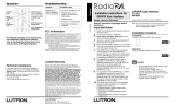
Button and LED Locations
LED states:
OFF ON Blink/Flash
See written instructions
at right.
Load Setup
Zones
Inputs
Figure B
Figure A
Figure C

Lutron Electronics Co., Inc. | 7200 Suter Road
Coopersburg, PA 18036-1299, U.S.A.
Help 1.800.523.9466 U.S.A., Canada and the Caribbean +1.888.235.2910 México +1.610.282.3800 Others
Assigning Zones to QSM Inputs (Occupancy, Daylight, IR)
1. Enter Zone Assignment. Press and hold the Program button on the Energi Savr NodeTM unit for 3 seconds. LEDs for Group 1
‘Occ’ and ‘Wired’ will blink once per second.
2. Select QSM. Press the Input button on the Energi Savr NodeTM unit to select ‘QSM’.
3. Wired inputs: Select inputs to display. Use the Option button on the Energi Savr NodeTM unit to sequence through the following
input groups. The option LEDs will blink to indicate which QSM input group is being displayed:
LED Input Group
Default
QSM wired inputs 1-4.
Select wired input. Each input from an associated QSM will be indicated by a steady on input LED as listed below:
LED Input Type
Occ Indicates an associated QSM occupancy sensor (wired and wireless).
Daylight Indicates an associated QSM daylight sensor (wired and wireless).
IR Indicates an associated QSM IR receiver (wired only).
Press the Program button to sequence through each associated input. The LED corresponding to the selected input will blink
(other associated input LEDs will remain steady on). Also, the LED of a sensor wired to a QSM will blink to help with identification.
Select wireless input:
Wireless Occupancy sensor: Press and hold the Lights Off or
button for 6 seconds, until the sensor’s dome begins to flash. The
Energi Savr NodeTM unit will automatically select that input.
Wireless Daylight sensor: Press and hold the Link button for 6 seconds, until the sensor’s dome begins to flash. The Energi Savr
Node
TM unit will automatically select that input.
4. Assign/Unassign zones. Simultaneously press the and buttons of any zone to assign or unassign the zone to/from the
selected input. A flashing ‘Zone’ LED indicates an assigned zone. A ‘Zone’ LED that is off indicates an unassigned zone.
Note: Any zone set to “Receptacle” load type cannot be assigned to a daylight sensor.
5. Exit Zone Assignment. Press and hold the Program button for 3 seconds to exit.
Assigning Zones to Pico® Wireless Controllers (through QSM)
1. Enter Pico® wireless controller Assignment. Simultaneously press and hold the top and bottom buttons on the Pico® wireless
controller for 3 seconds. The QSM will beep for 1 second and the ‘Status’ LED on the QSM will flash 3 times per second. The Input
LEDs on the Energi Savr NodeTM unit(s) will flash sequentially through each input group, and all unassigned zones will turn off.
2. Setup options. Press the Option button to select the desired option. The LED for the selected option will flash.
LED
Option
Default
‘Scene + off’
Opt 1
Scene mode
Opt 2
Zone Mode (default)
Save the selected option. Press and hold the Option button for 3 seconds. The LED for the selected option will remain steady
on.
Zone Mode: Set zone levels. Use the
and buttons to adjust zone preset light levels. Note: If a zone is left off and is assigned,
the default light level of 100% will be saved.
Scene Mode: Scene assignments are factory set. The top button is Scene 1, the bottom button is the Off Scene, and the Favorite
button (if present) is Scene 16. Refer to Scene Setup to adjust zone levels for each scene.
3. Assign/Unassign zones. Simultaneously press the and buttons of any zone to assign or unassign the zone. A blinking ‘Zone’
LED indicates an assigned zone. A ‘Zone’ LED that is off indicates an unassigned zone.
Repeat steps 2 and 3 for each desired zone-to-Pico wireless controller assignment.
Note: For any keypad assigned to control a receptacle zone, Raise/Lower will not control that zone.
4. Exit Pico® wireless controller Assignment. Simultaneously press and hold the top and bottom buttons on the Pico® wireless
controller for 3 seconds to exit.
Scene buttons and/or remote timeclock events can affect selected Energi Savr NodeTM zones.
1. Enter GRAFIK Eye® QS or QS Timeclock Programming. Simultaneously press and hold the top and bottom scene buttons
on the GRAFIK Eye® QS or QS Timeclock unit for 3 seconds. The input LEDs on the Energi Savr NodeTM unit(s) will flash sequentially
through each input group.
2a. For the GRAFIK Eye® QS (Optional; if associating scene buttons only, skip to Step 3): Add a Remote Timeclock Event.
Refer to the installation instructions for the GRAFIK Eye® QS control unit at www.lutron.com/qs. Add a Timeclock Event, and
choose Remote (not Local) as the event type. Return to the Timeclock menu on the GRAFIK Eye® QS control unit, and choose
“Program remote”. Choose the day and event, then perform Step 3 below. Press OK on the GRAFIK Eye® QS control unit. Repeat
for other events. Go to Step 4.
2b. For the QS Timeclock: Add a Timeclock Event. Refer to the installation instructions for the QS Timeclock, and add a
Timeclock Event. Return to the Timeclock menu on the QS Timeclock, and choose “Program remote”. Choose the day and event,
then perform Step 3 below. Press OK on the QS Timeclock. Repeat for other events. Go to Step 4.
3. Assign/Unassign Zones. Simultaneously press the and buttons of any zone to assign or unassign the zone. A blinking ‘Zone’
LED indicates an assigned zone. A ‘Zone’ LED that is off indicates an unassigned zone.
4. Exit GRAFIK Eye® QS or QS Timeclock Programming. Simultaneously press and hold the top and bottom scene buttons on
the GRAFIK Eye
® QS or QS Timeclock unit for 3 seconds to exit.
1. Enter Wallstation Programming. Simultaneously press and hold the top and bottom buttons (excluding raise/lower) on the
wallstation for 3 seconds. The Input LEDs on the Energi Savr NodeTM unit(s) will flash sequentially through each input group.
Note: On wallstations with dual columns, each column is set up separately.
2. Select option. Press the Option button on the Energi Savr NodeTM unit to select the scene wallstation type. LED for currently
saved type will remain steady on.
Flashing LED Scene Wallstation Type
Default
‘Scene + off’
Opt 1
‘Scene’
Opt 2
‘Zone Toggle’
Opt 3
‘Special Mode’ (Partitioning, Sequencing)*
* Wallstation must already be set up as a Partitioning or Sequencing Control. If any other Wallstation Type is selected for a Special
Mode wallstation, the wallstation is ‘reprogrammed’ to the selected type, and cannot be re-selected as a Special Mode wallstation.
Save option. Press and hold the Option button for 3 seconds to save the wallstation type. The LED for the selected wallstation
type will flutter for 1 second, then remain steady.
Select wallstation buttons (Zone Toggle only). To assign a specific Energi Savr Node
TM unit zone to a wallstation button, press
the wallstation button you wish to assign the zone to. The button LED will blink slowly.
Set zone levels (Zone Toggle only). Use the
and buttons to adjust zone preset light levels.
3. Assign/Unassign zones. All types: Simultaneously press then release the and buttons on the Energi Savr NodeTM unit to
assign/unassign each desired zone to a wallstation. A flashing ‘Zone’ LED indicates an assigned zone. A ‘Zone’ LED that is off
indicates an unassigned zone. Note: For any keypad assigned to control a receptacle zone, Raise/Lower will not control that zone.
4. Exit Wallstation Programming. Simultaneously press and hold the top and bottom buttons on the wallstation for 3 seconds to
exit.
QS Sensor Module (QSM) Zone Assignment
Wired seeTouch
® QS Wallstation Programming
GRAFIK Eye
® QS Control Unit or QS Timeclock Programming
Scene Selection Control
Refer to the Installation Instructions provided with the QSE-IO for proper DIP switch settings.
The Energi Savr NodeTM unit can be associated to a QSE-IO that is set in a Scene configuration. This can be used to change scenes
on your Energi Savr Node
TM unit using contact closure inputs on the QSE-IO, or to monitor scene changes on your Energi Savr
NodeTM unit using contact closure outputs on the QSE-IO.
To associate a QSE-IO that is set in a Scene configuration to an Energi Savr Node
TM unit(s):
1. Press and hold the Program button on the QSE-IO for 3 seconds. The 5 output LEDs on the QSE-IO will cycle. The input LEDs on
the Energi Savr Node
TM unit(s) will flash sequentially through each input group.
2. Assign/Unassign zones. Simultaneously press the and buttons of any zone to assign or unassign the zone. A blinking ‘Zone’
LED indicates an assigned zone. A ‘Zone’ LED that is off indicates an unassigned zone.
3. Exit Scene Selection Programming. Press and hold the Program button on the QSE-IO for 3 seconds.
Zone Toggle Control
Refer to the Installation Instructions provided with the QSE-IO for proper DIP switch settings.
The Energi Savr NodeTM unit can be associated to a QSE-IO that is set in Zone Toggle configuration. This can be used to toggle
zones on your Energi Savr NodeTM unit using contact closure inputs into the QSE-IO, or to monitor the state (on or off) of the zones
on your Energi Savr NodeTM unit using contact closure outputs out of the QSE-IO.
To associate a QSE-IO that is set in a Zone Toggle configuration to an Energi Savr Node
TM unit(s):
1. Enter Zone Toggle Programming. Press and hold the Program button on the QSE-IO for 3 seconds. The first output LED will
flash indicating “input 1” is selected. The input LEDs on the Energi Savr Node
TM unit(s) will flash sequentially through each input
group.
2. Select input. Tap the Program button on the QSE-IO to select an input. Corresponding LED will blink.
3. Set light levels. Use the and buttons on the Energi Savr NodeTM unit to set the desired light level for each zone.
4. Assign/Unassign zones. Simultaneously press the and buttons of any zone to assign or unassign the zone. A blinking ‘Zone’
LED indicates an assigned zone. A ‘Zone’ LED that is off indicates an unassigned zone.
Repeat steps 2-4 for each desired QSE-IO input.
5. Exit Zone Toggle Programming. Press and hold the Program button on the QSE-IO for 3 seconds to exit.
QSE-IO Input/Output Interface Programming
1.
1.
1.
1. 2. 4.
4.
2.
3.
4.
2.
2. 3.
QS Sensor Module (QSM) Zone Assignment
Wired seeTouch
® QS Wallstation Programming
GRAFIK Eye
® QS Control Unit or QS Timeclock Programming
Press and hold
3 seconds
Press and hold
3 seconds
Press and hold
3 seconds
Press and hold
3 seconds
Press and hold
3 seconds
Press and hold
3 seconds
Press
Press
Press Press
Press
Press simultaneously
Wired: Select Input Selected Input Blinks
Selected Input Blinks
4.
Assign Zones
Press Press and hold
3 seconds
Press
Press
Press
Select Option (optional) Save Option (optional)
3.
3.
Press simultaneously
Press simultaneously
Press simultaneously
Optional for
GRAFIK Eye
® QS
Assign Zone
Assign Zone
Assign Zones
Set Zone Level
(Zone Mode Only)
Set Zone Level
(Zone Toggle Only)
Select Button
(Zone Toggle Only)
Enter Zone Assignment
Enter Pico
® Wireless Controller Assignment
Enter Wallstation Programming
Enter QS Programming Add/Program Event Exit QS Programming
Exit Wallstation Programming
Select Option Save Option
Exit Pico
® Wireless Controller Assignment
5.
Exit Zone Assignment
Select QSM Wired: Select Inputs to Display
Assigning Zones to QSM Inputs (Occupancy, Daylight, IR) Scene Selection Control
Zone Toggle Control
Assigning Zones to Pico
® Wireless Controllers (through QSM)
Pre
ss
and hold
Press and hold
LUTRON
OK
Add events
Remote
Pre
ss
and
ho
ld
LUTRON
Press and hold
(Zone
Toggle
Only)
Pre
ss
and
ho
ld
1 button wallstation
Press and hold single
button
Dual column wallstations
Press and hold top and bottom
button of each column
S
ce
ne
Set Zone Level
3.
QSE-IO Input/Output Interface Programming
Press simultaneously
4.
Assign Zones
1.
Enter
Zone Toggle
Programming
5.
Exit
Zone Toggle
Programming
2.
Select Input
1. 3.2.
Press simultaneously
Assign Zones
Enter Scene Selection Programming Exit Scene Selection Programming
Press and hold
3 seconds
gg
Press and hold
Press and hold
3 seconds
gg
P
r
ess
a
n
d
ho
ld
Press
Press
Press and hold
3 seconds
Press and hold
3 seconds
Press and hold
3 seconds
Press and hold
3 seconds
Press and hold
3 seconds
Wireless: Select Occupancy Sensor Select
Daylight Sensor
Press and hold
6 seconds
Press and hold
6 seconds
Daylight
Sensor
Pre
ss
and
ho
ld
Wireless:
Select
Occupancy
Sensor
Press and hold
P
P
Figure E
Figure D
Figure F

CONTACT INFORMATION
Lutron Electronics Co., Inc. | 7200 Suter Road
Coopersburg, PA 18036-1299, U.S.A.
Help 1.800.523.9466 U.S.A., Canada and the Caribbean +1.888.235.2910 México +1.610.282.3800 Others
Press
Set Zone Levels
Partition Control
Sequencing Control
Set Zone Response to Occupancy Sensors
Select Scene for Occupied State
1.
1.
3.
2.
Press and hold
3 seconds
Press and hold
3 seconds
Press and hold 3 seconds
Press and hold
3 seconds
Press and hold
3 seconds
Press and hold
3 seconds
Press and hold
3 seconds
Press and hold
3 seconds
Press and hold
3 seconds
Press and hold
3 seconds
Press and hold
3 seconds
Press and hold
3 seconds
Press and hold
3 seconds
Press and hold
3 seconds
Press
Press simultaneously
Assign Zones
2.
Press simultaneously
3.
Press simultaneously
Assign Zones
Enter Partition Programming
Enter Sequencing Programming
Exit Sequencing Programming
Select Input
Press and ho
ld
Pre
ss
and
ho
ld
4.
Press and hold
3 seconds
Exit Partition Programming
Press and hold
Press and hold
Press
Partition Control
Refer to the Installation Instructions provided with the QSE-IO for proper DIP switch settings.
This can be used to join or detach scene activations between zones on an Energi Savr NodeTM unit and/or GRAFIK Eye® QS control
units based on the position of movable walls.
To associate a QSE-IO that is set in a Partition Control configuration to an Energi Savr Node
TM unit(s):
1. Enter Partition Control Programming. Press and hold the Program button on the QSE-IO for 3 seconds. The first output LED
will flash indicating “input 1” is selected. The input LEDs on the Energi Savr NodeTM unit(s) will flash sequentially through each input
group.
2. Select input. Tap the Program button on the QSE-IO to select an input. Corresponding LED will blink.
3. Assign zones. Simultaneously press then release the and buttons on the Energi Savr NodeTM unit to assign each desired zone
to “input 1” of the QSE-IO. A flashing ‘Zone’ LED indicates an assigned zone.
To unassign zones from the QSE-IO, simultaneously press then release the
and buttons for the desired zone. The ‘Zone’ LED will
turn off to indicate the zone is unassigned.
Repeat steps 2 and 3 for each desired QSE-IO input.
4. Exit Partition Control Programming. Press and hold the Program button on the QSE-IO for 3 seconds to exit.
Sequencing Control
Refer to the Installation Instructions provided with the QSE-IO for proper DIP switch settings.
The Energi Savr NodeTM unit can be associated to a QSE-IO that is set in Sequencing Control configuration. This can be used to
start and stop automatic sequencing of scenes 5-16.
To associate a QSE-IO that is set in a Sequencing Control configuration to an Energi Savr Node
TM unit(s):
1. Enter Sequencing Control Programming. Press and hold the Program button on the QSE-IO for 3 seconds. The first output
LED will flash indicating “input 1” is selected. The input LEDs on the Energi Savr NodeTM unit(s) will flash sequentially through each
input group.
2. Assign zones. Simultaneously press then release the and buttons on the Energi Savr NodeTM unit to assign each desired zone
to “input 1” of the QSE-IO. A flashing ‘Zone’ LED indicates an assigned zone.
To unassign zones from the QSE-IO, simultaneously press then release the
and buttons for the desired zone. The ‘Zone’ LED will
turn off to indicate the zone is unassigned.
3. Exit Sequencing Control Programming. Press and hold the Program button on the QSE-IO for 3 seconds to exit.
World headquarters
Lutron Electronics Co., Inc.
7200 Suter Road, Coopersburg, PA
18036-1299 USA
TEL +1.610.282.3800
FAX +1.610.282.1243
Technical Support 1.800.523.9466
European headquarters
United Kingdom
Lutron EA Ltd.
6 Sovereign Close, London,
E1W 3JF UK
TEL +44.(0)20.7702.0657
FAX +44.(0)20.7480.6899
Technical support
+44.(0)20.7680.4481
FREEPHONE 0800.282.107
Asian headquarters
Singapore
Lutron GL Ltd.
15 Hoe Chiang Road,
#07-03 Tower Fifteen,
Singapore 089316
TEL +65.6220.4666
FAX +65.6220.4333
Technical hotlines
France: 0800.90.12.18
Germany: 00800.5887.6635
Italy: 800.979.208
Spain: 900.948.944
Northern China: 10.800.712.1536
Southern China: 10.800.120.1536
Hong Kong: 800.901.849
Singapore: 800.120.4491
Taiwan: 00.801.137.737
Thailand: 001.800.120.665853
Other Areas in Asia: +65.6220.4666
Daylighting setup should be performed during the daytime when there is consistent but indirect sunlight. Dark, cloudy days or days
with highly variable cloud cover that frequently changes the sunlight conditions should be avoided. Additionally, times of day when
the sunlight penetrates directly into the space should be avoided (such as morning or evening).
Note: Any zone set to “Receptacle” load type cannot be assigned to a daylight sensor.
Set Daylight Sensor Setpoint
1. Enter Daylighting Setup. Simultaneously press and hold the Program and Input buttons for 3 seconds. LEDs for Group 1 Inputs
and ‘Default’ for each zone will flash.
2. Select option. Use the Option button to select ‘Opt1’.
3. Set light levels. Use the and buttons to set the approximate light level (or, in the case of switched zones, the minimum light
level) that you wish to maintain in the space.
4. Exit Daylighting Setup. Simultaneously press and hold the Program and Input buttons for 3 seconds to exit.
1. Simultaneously press and hold the Program and Option buttons for 3 seconds. Group 2 Input LEDs will flash, and the ‘Default’
LED will light.
2. Select Scene. Press the Option button to select a scene:
Scenes 1-4
LED Legend:
= steady on = off
Scene
#
LED
Pattern
Default
Level
Scene
#
LED
Pattern
Default
Level
1
100% 3 50%
2
75% 4 25%
Scenes 5-16
Press and hold the Option button for 10 seconds, then use the Option button to select a scene.
LED Legend:
= flashing = off
Scene
#
LED
Pattern
Default
Level
Scene
#
LED
Pattern
Default
Level
Scene
#
LED
Pattern
Default
Level
Scene
#
LED
Pattern
Default
Level
5
100% 8 100% 11 100% 14 100%
6
100% 9 100% 12 100% 15 100%
7
100% 10 100% 13 100% 16 100%
3. Set light levels. Use the and buttons to adjust the light level for each zone.
To make a zone unaffected, press and hold the button—the ‘High’, ‘Med’, and ‘Low’ LEDs will turn off. Continue holding until only
the ‘Med’ LED is steady on.
To make a zone affected again, press the
button until you see a combination of the ‘High’, ‘Med’, and ‘Low’ LEDs steady on or
flashing.
4. Exit Scene Setup. Simultaneously press and hold the Program and Option buttons for 3 seconds to exit.
Note: The fade time between scenes is factory set to 3 seconds, and is not adjustable.
Set Zone Response to Occupancy Sensors
1. Enter Occupancy Setup. Simultaneously press and hold the Program and Input buttons for 3 seconds. LEDs for Group 1 Inputs
and ‘Default’ for each zone will flash.
2. Select ‘Default’. Use the Option button to select ‘Default’.
Select response. Use the
and buttons to select the response type for each desired zone:
Flashing LED Zone Response Type
High
Occupancy mode (auto on/off)
Med
Vacancy mode (manual on/auto off)
Low
Afterhours mode*
* CCI must be set up for Afterhours mode (see section
, step 3e).
3. Exit Occupancy Setup. Simultaneously press and hold the Program and Input buttons for 3 seconds to exit.
Select Scene for Occupied State
Note: All zones use the same ‘Occupied Scene’ and cannot be set on a zone-by-zone basis. All zones use the ‘Off Scene’ for the
unoccupied/vacant state.
1. Enter Occupied State Setup. Simultaneously press and hold the Program and Option buttons for 3 seconds. Group 2 Input
LEDs will flash, and the ‘Default’ LED will light.
2. Select Scene. Press the Option button to select a scene:
Scenes 1-4
LED Legend:
= steady on = off
Scene
#
LED
Pattern
Default
Level
Scene
#
LED
Pattern
Default
Level
1
100% 3 50%
2
75% 4 25%
Scenes 5-16
Press and hold the Option button for 10 seconds, then use the Option button to select a scene.
LED Legend:
= flashing = off
Scene
#
LED
Pattern
Default
Level
Scene
#
LED
Pattern
Default
Level
Scene
#
LED
Pattern
Default
Level
Scene
#
LED
Pattern
Default
Level
5
100% 8 100% 11 100% 14 100%
6
100% 9 100% 12 100% 15 100%
7
100% 10 100% 13 100% 16 100%
3. Set ‘Occupied Scene’. Press and hold the Input button for 3 seconds to set the currently selected scene as the ‘Occupied
Scene’. The ‘QSM’ and ‘Wired’ LEDs will turn on to indicate the selection is complete.
4. Exit Occupied State Setup. Simultaneously press and hold the Program and Option buttons for 3 seconds to exit.
QSE-IO Input/Output Interface Programming - continued
Daylighting Setup
Scene Setup
Occupancy Setup
QSE-IO Input/Output Interface Programming - continued
Occupancy Setup
Daylighting Setup
Scene Setup
1.
1.
1. 4.3.
1.
4.
Pdhld3d
Pdhld
Pre
ss
and
ho
ld
Press and ho
ld
Press and hold
Pre
ss
and
ho
ld
3.
4.
Pre
ss
and
ho
ld
Pdhld
2.
2. 3.
2.
2.
3.
P
Press and hold
Press and hold
Pre
ss
and
ho
ld
Enter Occupancy Setup
Enter Daylighting Setup
Enter Occupied State Setup
Enter Scene Setup Enter Scene Setup
Exit Occupied State Setup
Press
Press
Press
Press
Press
Press
Press
Press
Select Option
Select Option
Select Scene
(Scenes 1-4)
Select Scene
(Scenes 1-4)
Set Occupied SceneSelect Scene
(Scenes 5-16)
Select Scene
(Scenes 5-16)
View Scenes 5-16
View Scenes 5-16
Change Setting
Set Zone Levels
Exit Occupancy Setup
Exit Daylighting Setup
Figure H
Figure G
Figure I
Figure J
/