Lutron Electronics GRAFIK Eye QSG-6PCE Operating instructions

Type
Operating instructions

This manual is also suitable for

LUTRON
System
Installation and
Operation Guide
R
Chinese
Please Read
Contents
Installation
Features and Functions of the GRAFIK Eye QS System . 2
Wiring the GRAFIK Eye QS System . . . . . . . . . . . . . . . . . 3
Wiring the GRAFIK Eye QS System
Class 2 / PELV Cable . . . . . . . . . . . . . . . . . . . . . . . . . 4
QS System Low-Voltage Control Wiring . . . . . . . . . . . . . .5
QS System Low-Voltage Terminal Connections . . . . . . . 6
Installing the GRAFIK Eye QS System . . . . . . . . . . . . . . . 7
Zone Setup . . . . . . . . . . . . . . . . . . . . . . . . . . . . . . . . . . . .8
Operation
Preprogrammed Button Functionality . . . . . . . . . . . . . . 10
General Functionality . . . . . . . . . . . . . . . . . . . . . . . . . . . 11
General Functionality: Programming Mode . . . . . . . . . .12
Zone Button Operation . . . . . . . . . . . . . . . . . . . . . . . . . .13
Quick Scene Programming . . . . . . . . . . . . . . . . . . . . . . 15
Scene Setup . . . . . . . . . . . . . . . . . . . . . . . . . . . . . . . . . .16
LED Displays for Lighting Levels . . . . . . . . . . . . . . . . . . 18
Adjusting Window Treatment Settings . . . . . . . . . . . . . .19
Timeclock Operation . . . . . . . . . . . . . . . . . . . . . . . . . . . .23
Set Save Mode . . . . . . . . . . . . . . . . . . . . . . . . . . . . . . . .28
Set Up Occupant Sensor . . . . . . . . . . . . . . . . . . . . . . . .29
Activate System Accessories . . . . . . . . . . . . . . . . . . . . .30
Faceplate Removal . . . . . . . . . . . . . . . . . . . . . . . . . . . . .30
Troubleshooting . . . . . . . . . . . . . . . . . . . . . . . . . . . . . . . .31
Menu Options . . . . . . . . . . . . . . . . . . . . . . . . . . . . . . . . .34
Warranty . . . . . . . . . . . . . . . . . . . . . . . . . . . . . . . . . . . . .35
Contact Information . . . . . . . . . . . . . . . . . . . . . . . . . . . .36
The GRAFIK Eye QS System allows for control of both lights and
shades or window treatments using a single control unit. Features
include pushbutton scene recall, info screen that displays energy
savings and status, IR receiver, astronomic timeclock, occupant
sensor connection, and backlit buttons that are easy to find and
operate.
Model Number Unit Capacity Zone Capacity
(watts) (watts)
QSG - 3PCE 1 500 500
QSG - 4PCE 2 000 500
QSG - 6PCE 2 300 500
(see page 8 for additional ratings)
All units: 230 V 50/60 Hz
R
GRAFIK Eye® QS System Installation and Operation Guide 2
OK
1 2 3 4 5 6
Info screen
Displays status;
programming functions
Lighting column
Scene buttons with integral
scene indicator LEDs
Shade column
Preset and raise/lower
buttons with integral LEDs
(maximum of 3 columns)
Space for future
shade columns
Zone numbers
Zone raise/lower buttons
Zone LEDs display current
lighting zone levels
Timeclock status button
Displays current
timeclock info
OK button
Used for programming
fade time
Infrared receiver
For handheld remote use
Master buttons
Temporarily raise and lower
lighting levels on unit
USB type mini B input
{
Hinged faceplate
Hinged faceplate
Features and Functions of the GRAFIK Eye® QS System
R
GRAFIK Eye® QS System Installation and Operation Guide 3
Wiring the GRAFIK Eye® QS System
Important Wiring Information
Use properly certified cable for all line
voltage/mains cables.
Proper short-circuit and overload
protection must be provided at the
distribution panel.
Install in accordance with all local and
national electrical codes.
Class 2 / PELV terminals may be
unplugged for ease of IR, occupant
sensor, and control wiring.
Caution! Before connecting the
loads to the control unit, test the
loads for short-circuits.
1.Turn power OFF at the circuit breaker or
fuse box.
2.Connect a standard light switch between
the live lead and load wire to test the
circuit.
3.Turn power ON and check for short or
open circuits. If load does not operate,
the circuit is open. If the breaker/MCB
trips (fuse blows or opens), a load short
may exist. Correct short or open circuits
and test again.
Caution! Do not connect line
voltage/mains cable to Class 2 /
PELV terminals.
Earth/ground terminal connection must
be made as shown in wiring diagrams.
Do not mix different load types on the
same zone.
Follow all local and national electrical
codes when installing Class 2 / PELV
wiring with line voltage/mains wiring.
Test for short-circuits on loads before
wiring QS control unit.
To connect the line voltage/mains
cables to the control unit:
1.Strip 8 mm (5/16 in.) of insulation off the
line voltage/mains cables in the wallbox.
2.Connect the line voltage/mains, ground,
and load wires to the appropriate
terminals on the back of the control unit.
The recommended installation torque is
0,6 N•m (5,0 in.-lbs.) for line
voltage/mains connections and 0,6 N•m
(5,0 in.-lbs.) for the earth/ground
connection.
3/8 in. (10 mm)
8 mm
(5/16 in.)
Danger! GRAFIK Eye QS control units must be installed by a qualified electrician
in accordance with all applicable regulations and building codes. Improper
wiring can result in personal injury or damage to control units or other
equipment. Always turn off circuit breaker or remove main fuse from power line
before doing any work. To avoid overheating and possible damage to
equipment, do not install dimming devices to dim receptacles, motor-operated
appliances, or fluorescent lighting not equipped with Lutron Hi-lume®, Eco-10TM,
or Tu-Wire® electronic dimming ballasts, or devices approved for your location.
In dimmed magnetic low-voltage circuits, you can prevent transformer
overheating and failure by avoiding excessively high current flow: Do not operate
control units with any lamps removed or burned out; replace any burned out
lamps immediately; use only transformers that incorporate thermal protection or
fused primary windings. Control units are designed for residential and
commercial use, for indoor use only.
Neutral
Hot/Live
Switch
Load
Occupant Sensor Wiring
R
GRAFIK Eye® QS System Installation and Operation Guide 4
1234
1: COM
2: 24 V
3: MUX
4: MUX
12
ABC
Note: Use appropriate wire connecting devices as
specified by local codes.
Occupant
sensor
123456LN
Distribution Panel
LN
To Load 1
To Load 2
To Load 3
To Load 4
To Load 5
To Load 6
Control Wiring
Wiring the GRAFIK Eye® QS System
Class 2 / PELV USA Cable
IR Wiring
From external
IR connection
(by others)
Common and power (terminals 1 and 2):
Two 1,0 mm
2
(#18 AWG) each terminal
1,0 mm
2
(#18 AWG)
each terminal
2,5 mm
2
(#12 AWG)
each terminal
1234
12
ABC
123456LN
1,0 mm
2
(#18 AWG)
each terminal
230 V
1: IR DATA
2: IR COM
A: OCC SIG
B: 24 V
C: OCC COM
To control stations,
window treatments, or
other GRAFIK Eye QS
control units
Line Voltage/Mains Cables
and Load Wiring
Data (terminals 3 and 4):
Twisted, shielded pair 1,0 mm
2
(#22 AWG)
each terminal
R
GRAFIK Eye® QS System Installation and Operation Guide 5
System communication uses Class 2 /
PELV low-voltage wiring.
Follow all local and national electrical
codes when installing Class 2 / PELV
wiring with line voltage/mains wiring.
Each terminal accepts up to two 1,0 mm
2
(#18 AWG) wires.
Total length of control link must not
exceed 610 m (2 000 ft.).
Make all connections in the control unit’s
wallbox.
A QS system can have up to 100 zones
and 100 devices (see table below).
Wiring can be T-tapped or daisy-chained.
Wire sizes:
- Two 1,0 mm
2
(#18 AWG) conductors for
control power.
- One twisted, shielded pair of 1,0 mm
2
(#22 AWG) for data link.
- Cable is available from Lutron:
GRX-CBL-S-500 (non-plenum)
GRX-CBLP-S-500 (plenum rated).
Check compatibility in your area.
LUTRON
LUTRON
LUTRON
LUTRONLUTRON
LUTRON
LUTRON
GRAFIK Eye QS
Sivoia QS
seeTouch QS
LUTRON
LUTRON
LUTRON
LUTRON LUTRON LUTRON
LUTRON
Daisy-Chain Wiring Example
T-Tap Wiring Example
GRAFIK Eye QS
Sivoia QS
QS smart
power
supply panel
QS smart power
supply panel
seeTouch QS
QS System Low-Voltage Control Wiring
System Limits
QS Device Zone Count Device Count
3-zone QS 3 1
4-zone QS 4 1
6-zone QS 6 1
seeTouch
QS 0 1
Sivoia
QS 1 1
QS smart power supply panel 0 1
LUTRON
LUTRON
LUTRON
LUTRON
QS System Low-Voltage Terminal Connections
R
GRAFIK Eye® QS System Installation and Operation Guide 6
4
3
2
1
4
3
2
1
4
3
2
1
4
3
2
1
4
3
2
1
4
3
2
1
4
3
2
1
1234
12
ABC
123456HN
1234
12
ABC
123456HN
1234
12
ABC
123456HN
1234
12
ABC
123456HN
A1
2
3
4
1
A2
A3
A1 powers wallstation 1 only; terminal
2 terminates at wallstation 1
A2 and A3
have their
own power
supply; no
terminal 2
connection
A3 powers
wallstations 2,
3, and 4
A4
P1
S1
A4 powers wallstations
5, 6, and 7
P1 powers
shade S1
only
Sivoia QS
shade
QS smart
power supply
panel
Control units shown in rear view
5
6
7
Connect the terminal 1, 3, and 4
connections to all control units,
wallstations, and control interfaces.
Each control unit has its own power
supply. Terminate the terminal 2
connection (24 V power) so that each
control unit supplies power to a
maximum of three wallstations. Each
wallstation should receive power from
only one control unit.
No terminal 2
connection between
wallstations 4 and 5;
they are powered by
different control units
R
GRAFIK Eye® QS System Installation and Operation Guide 7
Installing the GRAFIK Eye® QS System
1.Mount a 89 mm (3 1/2-in.) deep
4-gang wallbox on a dry, flat indoor
surface that is accessible and allows
for system programming and
operation. Allow at least 110 mm
(4 1/2 in.) clearance above and below
the faceplate to ensure proper heat
dissipation. Allow 25 mm (1 in.) for
faceplate overhang on all sides.
Note: 4-gang wallbox available from
Lutron; P/N 241400.
2.Mount the control unit in the wallbox
as shown using the four screws
provided.
Note: Follow all local and national
electrical codes when installing Class
2 PELV wiring with line voltage/mains
wiring.
3.Apply the protective overlay to the
control unit. See page 14 for
instructions for naming zones.
Test the Wiring
1.Restore power.
2.Press the top button on the lighting
keypad. The LED will light.
3.Press the zone raise or lower button.
Make sure the control unit is dimming all
connected loads.
Protective overlay
(apply after installation)
Note: When tightening mounting
screws, make sure that the hinged
cover and faceplate will open fully,
as shown.
Wall
200 mm
(7.9 in.)
87 mm
(3.5 in.)
95 mm
(3.75 in.)
LUTRON
LUTRON
Faceplate overhangs
wallbox on all sides;
allow 25 mm (1 in.)
110 mm
(4.5 in.)
Zone Setup
Assign Load Type
1. Enter programming mode (see page 12).
2. Use the master buttons to highlight “Zone
setup” and press the OK button to
accept.
3. Use the master buttons to highlight “Load
type”. Press the OK button to accept.
4. Use the zone raise/lower buttons to
choose the load type for that zone. See
the list below for supported load types.
Press the OK button to accept.
5. The info screen will display a
confirmation screen that your load type
has been saved.
6. Exit programming mode (see page 12).
R
GRAFIK Eye® QS System Installation and Operation Guide 8
Main menu
Occ sensor
Zone setup
Zone setup
High end
Load type
Set type using
zone controls
Load type
OK
1 2 3 4 5 6
Use the
zone
raise/lower
buttons to
choose the
load type for
that zone.
Master
buttons
OK
button
Load Type Notes
All electronic low-voltage (ELV) lighting
used with an interface must be rated for
reverse phase control dimming. Before
installing an ELV light source, verify with
the manufacturer that their transformer
can be dimmed. When dimming, an ELV
interface must be used with the control
unit.
Not all zones must be connected;
however, connected zones must have a
minimum load of 40 W.
No zone may be loaded with more than
500 W.
Maximum total lighting load per unit is
10 A.
Maximum total lighting load for a
magnetic low-voltage (MLV) load is
2 300 VA or 1 800 W after transformer.
Maximum load per MLV zone is 500 VA or
400 W.
Setting Load Types
Fixture load type
Incandescent
MLV (magnetic low-voltage)
ELV (electronic low-voltage)
Hi-Lume
/
Eco-10
Non-dim
Neon/Cold cathode
Tu-Wire
Direct control via
GRAFIK Eye QS
Incandescent
MLV
--
--
Non-dim LOFO or Non-dim FOFO
Neon, CC
Tu-Wire
Control via
power module
Power module
Power module
Power module
Fluorescent module
Non-dim LOFO or Non-dim FOFO
Neon, CC
Tu-Wire
LUTRON
LUTRON
Choose this load type from the menu
on the GRAFIK Eye® QS:
Saved
Saved
Set Minimum Level (optional)
Some local regulations specify a
minimum lighting level for dimming
zones in occupied buildings. If this
pertains to you, follow these steps to
set up your minimum lighting level.
1. Enter programming mode (see page 12)
and select “Zone setup,” then “Min
level”. Press the OK button to accept.
2. Use the master buttons to highlight
“OFF” if you want your lights to go all
the way off at their minimum light level,
or “10%” if you want that to be the
minimum light level. Press the OK button
to accept.
Note: Non-dim loads will turn off
regardless of the minimum level setting.
3. The info screen will display a
confirmation screen that your minimum
level has been saved.
4. Exit programming mode (see page 12).
R
GRAFIK Eye® QS System Installation and Operation Guide 9
Zone Setup
Set High End or Low End
High and low end trim settings limit the
maximum and minimum output of a
dimming zone. Trim levels are set
automatically when the load type is
programmed. Change the high or low
end trim for a zone only if the default
setting needs to be adjusted.
1. Enter programming mode (see page 12).
2. Use the master buttons to highlight “Zone
setup” and press the OK button to
accept.
3. Use the master buttons to highlight “High
end” or “Low end” (this example shows
low end). Press the OK button to accept.
4. Use the zone raise/lower buttons to set
the high end or low end trim for that
zone.
The info screen will display each zone
number and percentage as you adjust it.
Press the OK button to accept.
5. The info screen will display a
confirmation screen that your setting has
been saved.
6. Exit programming mode (see page 12).
Main menu
Occ sensor
Zone setup
Zone setup
High end
Low end
Set trim using
zone controls
Zone 2
Low end
OK
1 2 3 4 5 6
Use the
zone
raise/lower
buttons to
set the high
end or low
end trim for
that zone.
Master
buttons
OK
button
10%
Min level
OFF
Zone setup
Low end
Min level
Saved
Saved
Saved
Saved
Preprogrammed Button Functionality
R
GRAFIK Eye® QS System Installation and Operation Guide 10
Lighting Column Button Preprogramming
(Factory Default: Dimmable Loads)
Scene 1: All lights to 100%
Scene 2: All lights to 75%
Scene 3: All lights to 50%
Scene 4: All lights to 25%
Scene OFF: All lights to 0%
Lighting Column Button Preprogramming
(Factory Default: Non-Dim Loads)
Scene 1: All lights On
Scene 2: All lights On
Scene 3: All lights On
Scene 4: All lights On
Scene OFF: All lights Off
Shade Column Button Preprogramming
(Factory Default: Sivoia® QS shades)
All shades fully open
All shades to 50%
All shades fully closed
Lower/Raise all shades
The GRAFIK Eye® QS System controls lights without special programming. The factory
defaults for the lighting column buttons are shown below for both dimmable and non-
dim zones. See pages 15 through 17 for methods for changing scene settings.
The info screen goes blank after 20
seconds if there is no button press or
fading.
The master buttons also activate the info
screen. These buttons temporarily raise or
lower all dimmable lights (except those
programmed as unaffected in the current
scene). Adjustments are temporary and do
not affect scene programming.
The OK button activates the info screen,
which then shows the current scene and its
fade time.
The timeclock button activates the info
screen and displays the current time, the
next event scheduled to occur, and what
that next event is. Pressing a second time
displays the location and the
sunrise/sunset times.
R
GRAFIK Eye® QS System Installation and Operation Guide 11
OK
Info screen: see example screens below
Timeclock button displays the current
time and the next scheduled event.
Pressing when in Program mode
functions as a
“back” button.
OK button activates the info screen,
which shows the current scene’s fade
time. In Save Always mode, allows fade
time adjustment. In
Save by OK
mode, pressing
a second time
allows zone
adjustment;
pressing a third
time allows fade
adjustment.
Master buttons temporarily raise or lower
all lights (except unaffected, shades, and
non-dim zones) on this GRAFIK Eye QS
unit
Scene 1
Master raise
Master lower
General Functionality
OK
Scene: 1
Adjust fade
03 seconds
11:23 AM Fri
Next: 5:00 PM
Scene 1
Entering and Exiting Programming Mode
To enter programming mode:
Press and hold simultaneously the top and
bottom buttons on the lighting column for 3
seconds.The LEDs in the lighting buttons
will scroll from top to bottom, confirming
that you are in programming mode, and the
info screen will display the main menu.
To exit programming mode:
Press and hold simultaneously the top and
bottom buttons on the lighting column for
3 seconds. The info screen will go to
Scene 1.
Navigating Menus in Programming Mode
Master Buttons
The master buttons allow you to move through the menu
choices. The current choice is highlighted on the info screen.
OK Button
The OK button chooses the current highlighted menu choice.
This will either take you to the next menu or accept a setting you
have selected.
Timeclock Button
The timeclock button functions as a “back” button during
programming mode. Pressing the timeclock button takes you
back one step in the current menu. Pressing it repeatedly will
eventually return you to the main menu, but will not exit
programming mode.
R
GRAFIK Eye® QS System Installation and Operation Guide 12
General Functionality: Programming Mode
OK
Press and hold the top and
bottom buttons for 3 seconds
to enter or exit programming
mode
Master buttons
OK button
Timeclock button
Main menu
Scene setup
Timeclock
Scene 1
Fade time
3 seconds
Info screen display
when you enter
programming mode
Info screen display
when you exit
programming mode
Zone Button Operation
Each column of buttons represents one
zone of lights. Pressing any button on a
column turns on the info screen and
displays the zone’s current light level and
current energy savings.
Pressing the raise and lower buttons on a
zone causes different actions depending
on zone type (see below).
Dimmable zones:
Press and hold to raise/lower all lights in a
zone; release to stop
Press raise or lower to stop a zone that is
fading
Raising lights from off to full on or lowering
from full on to off takes 5 seconds
Press raise and lower simultaneously to
toggle between full on and off
Non-dim zones:
Press raise to take light zones to full on
Press lower to take light zones to off
R
GRAFIK Eye® QS System Installation and Operation Guide 13
1 2 3 4 5
2 3
Zone Raise
Zone Lower
LEDs indicate light level
Note: See page 18 for an
explanation of the LED
display for each type of
load in a zone.
R
GRAFIK Eye® QS System Installation and Operation Guide 14
Zone Button Operation
Name a Zone
1. Enter programming mode (see page 12).
2. Use the master buttons to highlight “Zone setup”
and press the OK button to accept.
3. Use the master buttons to highlight “Label” and
press the OK button to accept.
4. Use the master buttons to change the zone
number to your desired zone. Custom zone labels
will appear if previously set. Press the OK button
to accept.
5. Use the master buttons to highlight “Custom” and
press the OK button to accept. Or, highlight
“Default” to return the zone label to the default
(e.g., Zone 1).
6. Use the master buttons to scroll through the
characters (lowercase and uppercase letters, plus
numbers 0-9). The character you are currently
changing will be underlined on the screen. Press
OK to select the character you want, then repeat
for all available characters. Choose a space (no
character) and press OK for any remaining
characters. Press the OK button to accept.
Note: Custom zone labels will always begin with
the zone number and a colon (e.g., 1: Uplights).
7. The info screen will display a confirmation screen
that your name has been saved.
8. Exit programming mode (see page 12).
Main menu
Occ sensor
Scene setup
Zone setup
Zone setup
Min level
Select zone:
Zone 2
Label
Label zone 2
Custom
Label zone 2
1: A
A
1 / 12
OK
Master
buttons
OK
button
Saved
Saved
Quick Scene Programming
Save Always Mode
The default save mode (see page 28) is
Save Always. This mode allows you to
quickly set scenes on the lighting column
without entering program mode.
1.Press the button for the scene you want
to set; its LED will light and the lights will
go to the current settings.
2.Use the zone raise/lower buttons to set
all lights to the desired levels. Press the
OK button.
3.To set the fade time for this scene, press
the OK button, then use the master
buttons to set the desired fade time.
Press the OK button to save.
Note: Using the master buttons to raise
or lower lighting settings is still temporary
in Save Always mode.
R
GRAFIK Eye® QS System Installation and Operation Guide 15
OK
1 2 3 4 5 6
1. Press the lighting column scene button
you wish to program.
2. Use the zone raise/lower buttons to set
light levels.
3. Use the master buttons to set fade time.
Scene Setup
Program a Scene
1. Enter programming mode (see page 12).
2. Use the master buttons to highlight “Scene setup” and
press the OK button to accept.
3. Use the master buttons to select “Levels” to adjust lighting
and/or window treatment levels. Press the OK button to
accept. Use the master buttons to select the scene
number of your desired scene. Press the OK button to
accept.
4. Set each zone to the desired light level for this scene using
the zone raise/lower buttons. The info screen will display
the zone and percentage as you adjust it.
To set a zone as unaffected, lower the light levels all the
way to off, then hold the zone lower button for 3 seconds.
When all zones are at the desired level, press the OK
button to accept.
5. Use the master buttons to set the fade time for this scene.
Press the OK button to accept.
6. Press the button on a shade column that will take the
window treatments assigned to that shade column to the
level you want for this scene. Repeat for any additional
shade columns. Press the OK button to accept. Or, if you
do not have or do not wish to set shade groups for this
scene, press OK.
7. The info screen will display a confirmation screen that your
scene has been saved.
8. Exit programming mode (see page 12).
R
GRAFIK Eye® QS System Installation and Operation Guide 16
OK
Master
buttons
OK
button
Main menu
Timeclock
Scene setup
Scene setup
Labels
Scene setup
Levels
Scene setup
Scene 1
Adjust fade
3 seconds
Scene 1
Set shade
groups
3 seconds
Scene 1
Set zones
Scene 1
Saved
Saved
1 2 3 4 5
2 3
Zone Raise
Zone Lower
R
GRAFIK Eye® QS System Installation and Operation Guide 17
Scene Setup
Name a Scene
1. Enter programming mode (see page 12).
2. Use the master buttons to highlight “Scene setup”
and press the OK button to accept.
3. Use the master buttons to highlight “Labels” and
press the OK button to accept.
4. Use the master buttons to change the scene
number to your desired scene. Press the OK
button to accept.
5. Use the master buttons to highlight “Custom” and
press the OK button to accept.
6. Use the master buttons to scroll through the
characters (lowercase and uppercase letters, plus
numbers 0-9). The character you are currently
changing will be underlined on the screen. Press
OK to select the character you want, then repeat
for all available characters. Choose a space (no
character) and press OK for any remaining
characters. Press the OK button to accept.
7. The info screen will display a confirmation screen
that your name has been saved.
8. Exit programming mode (see page 12).
Main menu
Occ sensor
Scene setup
Scene setup
Labels
Select scene:
Scene 1
Label scene 1
Custom
Label scene 1
1: A
A
1 / 11
OK
Master
buttons
OK
button
Scene setup
Levels
Labels
Labels
Saved
Saved
LED Displays for Lighting Levels
Dimmable Lights Non-Dim Lights
Off
1-17%
18-34%
35-51%
52-68%
69-85%
86-99%
On/100%
Unaffected
(lights are not affected
by scene button
or master raise/lower)
R
GRAFIK Eye® QS System Installation and Operation Guide 18
Legend:
LED lit
LED off
Setting Limits
Note: Entering Limit Setup mode
may cause window treatments to
move approximately 203.2 mm
(8 in.)up or down. Be sure that
each window treatment is
positioned so that the fabric can
safely move 203.2 mm (8 in.) up
or down before entering Limit
Setup mode.
1. On any shade column,
press and hold
simultaneously the top
and raise buttons. The
LEDs next to the top
and bottom buttons will
cycle.
Note: At any time while
in Limit Setup mode,
you can move all
window treatments
together to their current
open limit by double-
tapping the top button,
or to their current close
limit by double-tapping
the bottom button.
Note: Once EDUs (electronic drive units
of the window treatment) have been
assigned to shade columns, limits can be
set for an EDU only using the shade
column it is assigned to, and a shade
column can set limits only for those EDUs
assigned to it.
2.Select the EDU you want to to adjust
using the top button on the shade
column. Each time you press and release
the top button, a different EDU that is
assigned to that shade column will open
and close in an 203.2 mm (8 in.) range to
indicate it is selected. Press the top
button until the EDU for the window
treatment you wish to adjust moves. (You
can also use the bottom button, which
moves through the assigned EDUs in the
opposite order.)
3. Adjust the currently selected
EDU to the desired level for
the open limit (the maximum
the window treatment is
allowed to open) using the
raise and lower buttons.
4.Press and hold the top button on the
shade column for 5 seconds to store the
current position as the open limit. The
LED next to the top button will flash
quickly for 2 seconds.
5.Adjust the currently selected EDU to the
desired level for the close limit (the
maximum the window treatment is
allowed to close) using the raise and
lower buttons.
6.Press and hold the bottom button on the
shade column for 5 seconds to store the
current position as the close limit.The
LED next to the bottom button will flash
quickly for 2 seconds.
7.Repeat steps 2 through 6 to set the open
and close limits for each window
treatment assigned to the shade column.
8.Press and hold simultaneously the top
and raise buttons on the shade column to
exit Limit Setup mode.
R
GRAFIK Eye® QS System Installation and Operation Guide 19
Adjusting Window Treatment Settings
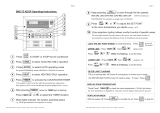
Assigning EDUs to Shade Columns
Note: Entering Assignment mode
will cause the window treatments
to move between their open and
close limits. Be sure that the
open and close limits have been
set correctly.
1. Press and hold
simultaneously the top
and bottom buttons on
the shade column for 5
seconds to enter
programming mode.
The LEDs next to the
buttons will flash once
per second. EDUs
(electronic drive units of
the window treatments)
assigned to that shade
column will move to
their close limit, and
EDUs not assigned to
that shade column will
move to their open
limit.
2.To assign an EDU to the shade column
that is program mode, use one of the
following methods:
- Press and release the top button on the
shade column that is in program mode.
Each time you press and release the top
button, a different EDU that is assigned to
that shade column will open and close in
an 203,2 mm (8 in.) range. Press the top
button until the EDU you wish to assign
to the shade column moves. (You can
also use the bottom button, which moves
through the EDUs in the opposite order.)
- Or, press and release any button on an
EDU to toggle between unassignment
and assignment for that EDU’s window
treatment to the shade column.
Assign or unassign the currently selected
EDU to the shade column using the raise
and lower buttons.
The lower button assigns the selected
EDU.
The raise button unassigns the selected
EDU.
3.Check window treatment assignments:
EDUs for window treatments assigned to
the shade column will be at their close
limit, and EDUs for window treatments
not assigned to the shade column will be
at their open limit.
4.Press and hold simultaneously the top
and bottom buttons on the shade column
for 5 seconds to exit Assignment mode.
The LEDs next to the buttons will stop
flashing, and the EDUs assigned to the
shade column will return to their levels
before entering Assignment mode.
Note: Once you have assigned window
treatments to a shade column, you will
notice the following additional
functionality:
- When some or all EDUs assigned to a
shade column are moving, press and
release the top, middle, or bottom
button to immediately stop all assigned
EDUs.
- The position that each EDU moves to
when the middle button is pressed is
now reprogrammable. See Preset
Adjustment on page 21.
- No matter how or from where their
movement is commanded, whenever all
the assigned EDUs come to a stop and
match their programmed positions for
one of the buttons in the shade column,
the LED next to that button will
automatically light up.
R
GRAFIK Eye® QS System Installation and Operation Guide 20
Lower button
(assign)
Raise button
(unasssign)
Adjusting Window Treatment Settings
  • Page 1 1
  • Page 2 2
  • Page 3 3
  • Page 4 4
  • Page 5 5
  • Page 6 6
  • Page 7 7
  • Page 8 8
  • Page 9 9
  • Page 10 10
  • Page 11 11
  • Page 12 12
  • Page 13 13
  • Page 14 14
  • Page 15 15
  • Page 16 16
  • Page 17 17
  • Page 18 18
  • Page 19 19
  • Page 20 20
  • Page 21 21
  • Page 22 22
  • Page 23 23
  • Page 24 24
  • Page 25 25
  • Page 26 26
  • Page 27 27
  • Page 28 28
  • Page 29 29
  • Page 30 30
  • Page 31 31
  • Page 32 32
  • Page 33 33
  • Page 34 34
  • Page 35 35
  • Page 36 36

Lutron Electronics GRAFIK Eye QSG-6PCE Operating instructions

Type
Operating instructions
This manual is also suitable for

Ask a question and I''ll find the answer in the document

Finding information in a document is now easier with AI