Lutron Electronics seeTouch guestroom solutions Installation guide
- Type
- Installation guide
Lutron Electronics seeTouch guestroom solutions:
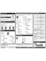
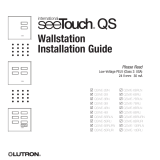
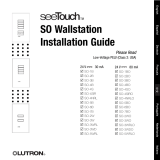
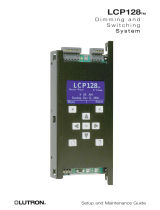
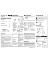
This device offers a cost-effective and simple-to-install lighting control solution for hotel guestrooms. The precision-engineered dimming panel sets up lighting scenes and shade presets, and provides individual control of light sources. Additionally, it features a built-in astronomic timeclock. Communicating seamlessly with lights, motorized window treatments, and control stations, the seeTouch guestroom solution is compatible with all Lutron® QS system components.
Lutron Electronics seeTouch guestroom solutions:
This device offers a cost-effective and simple-to-install lighting control solution for hotel guestrooms. The precision-engineered dimming panel sets up lighting scenes and shade presets, and provides individual control of light sources. Additionally, it features a built-in astronomic timeclock. Communicating seamlessly with lights, motorized window treatments, and control stations, the seeTouch guestroom solution is compatible with all Lutron® QS system components.


-
 1
1
-
 2
2
-
 3
3
-
 4
4
-
 5
5
-
 6
6
-
 7
7
-
 8
8
-
 9
9
-
 10
10
-
 11
11
-
 12
12
-
 13
13
-
 14
14
-
 15
15
-
 16
16
-
 17
17
-
 18
18
-
 19
19
-
 20
20
-
 21
21


Lutron Electronics seeTouch guestroom solutions Installation guide
- Type
- Installation guide
Lutron Electronics seeTouch guestroom solutions:
This device offers a cost-effective and simple-to-install lighting control solution for hotel guestrooms. The precision-engineered dimming panel sets up lighting scenes and shade presets, and provides individual control of light sources. Additionally, it features a built-in astronomic timeclock. Communicating seamlessly with lights, motorized window treatments, and control stations, the seeTouch guestroom solution is compatible with all Lutron® QS system components.
Ask a question and I''ll find the answer in the document
Finding information in a document is now easier with AI
Related papers
-
 Lutron Electronics seeTouch QSWS2-2B Installation guide
-
 Lutron Electronics Energi Savr Node QSN-4S16-S-347 Programming Manual
-
 Lutron Electronics seeTouch QS Series Installation guide
-
 Lutron Electronics seeTouch QS Series Installation guide
-
 Lutron Electronics SO-6BO Installation guide
-
Lutron Electronics GRAFIK Eye QSGRJ-4P Operating instructions
-
 Lutron Electronics LCP128 Setup And Maintenance Manual
-
 Lutron Electronics MyRoom Operation and Maintenance Manual
-
 Lutron Electronics Sivoia QED Technical Reference Manual
-
 Lutron Electronics radioRA GRAFIK Eye RA-GRXI Installation guide


Other documents
-
Aurora AR-WC-WH Installation guide
-
Lutron MA-LFQ3-AL User guide
-
-
Clear-Com Eclipse HX CCI-22 User manual
-
-
 Maestro IR MIR-ITFS-LF User manual
-
-
Pando 6521 Datasheet
-
Eaton Greengate RC3D-PL-CP Installation guide
-
Lutron Q-POE-8 PoE Switch User manual
