Page is loading ...


PowerFlex
®
700L Liquid-Cooled Drive User Manual
Important User
Information
Solid state equipment has operational characteristics differing from those of
electromechanical equipment. Safety Guidelines for the Application, Installation and
Maintenance of Solid State Controls (Publication SGI-1.1 available from your local
Rockwell Automation sales office or online at
http://www.rockwellautomation.com/
literature) describes some important differences between solid state equipment and
hard-wired electromechanical devices. Because of this difference, and also because of
the wide variety of uses for solid state equipment, all persons responsible for applying
this equipment must satisfy themselves that each intended application of this
equipment is acceptable.
In no event will Rockwell Automation, Inc. be responsible or liable for indirect or
consequential damages resulting from the use or application of this equipment.
The examples and diagrams in this manual are included solely for illustrative
purposes. Because of the many variables and requirements associated with any
particular installation, Rockwell Automation, Inc. cannot assume responsibility or
liability for actual use based on the examples and diagrams.
No patent liability is assumed by Rockwell Automation, Inc. with respect to use of
information, circuits, equipment, or software described in this manual.
Reproduction of the contents of this manual, in whole or in part, without written
permission of Rockwell Automation, Inc. is prohibited.
Throughout this manual, when necessary we use notes to make you aware of safety
considerations.
Important: Identifies information that is critical for successful application and
understanding of the product.
Allen-Bradley, PowerFlex, DPI, and DriveLogix are either registered trademarks or trademarks of Rockwell Automation, Inc.
!
WARNING: Identifies information about practices or
circumstances that can cause an explosion in a hazardous
environment, which may lead to personal injury or death, property
damage, or economic loss.
!
ATTENTION: Identifies information about practices or
circumstances that can lead to personal injury or death, property
damage, or economic loss. Attentions help you identify a hazard,
avoid a hazard, and recognize the consequences.
Shock Hazard labels may be located on or inside the equipment
(e.g., drive or motor) to alert people that dangerous voltage may be
present.
Burn Hazard labels may be located on or inside the equipment
(e.g., drive or motor) to alert people that surfaces may be at
dangerous temperatures.

PowerFlex® 700L Liquid-Cooled Drive User Manual
Publication 20L-UM001D-EN-P
Summary of Changes
The information below summarizes the changes to this manual since its last
release (July 2007):
Description of New or Updated Information Page(s)
Revised conditions in the “Essential Requirements for CE Compliance” section. 1-8
Corrected overall height dimension in Figure 2.1 and Detail A dimension. 2-2
In the Equipment Lifting section, added subsection “Attaching the Lifting Feet to the Drive.” 2-4
Added Frame 2 information to remove PowerFlex 700S Phase II Control cassette. 2-8
Added Frame 2 “Selecting/Verifying Control Transformer Voltage” section. 2-12
In Figure 2.14, added Frame 2 TB1 details when TB4 is not present. 2-19
Added Frame 2 control synchronization information for 700S Phase II Control. 2-21
Added new information for Frame 3A and 3B to install the vented top cover. 3-16
Added “Selecting/Verifying Control Transformer Voltage” section for Frame 3A & 3B. 3-23
Updated Table 4.A and Table 4.G. 4-5 and 4-8
Added action to take for Table 6.B and 6.C. 6-4 and 6-5
Added PowerFlex 700S Phase II Control information to specifications. A-2 and A-3
Added Derating Guidelines. A-4
Added Tables A.H, A.I, A.J, and H.K for Frame 3A and 3B common bus inverter power module DC input fusing. A-7 and A-8
Added new schematic for Frame 2 drive without TB4 connections. B-4


PowerFlex® 700L Liquid-Cooled Drive User Manual
Publication 20L-UM001D-EN-P
Table of Contents
Preface Overview
Who Should Use this Manual? . . . . . . . . . . . . . . . . . . . . . . . . . . . . . . . . . . . . . . . . . . . . . P-1
What Is Not in this Manual . . . . . . . . . . . . . . . . . . . . . . . . . . . . . . . . . . . . . . . . . . . . . . . . P-1
PowerFlex 700L Active Converter Power Module Information . . . . . . . . . . . . . . . . . . P-1
PowerFlex 700 Vector Control Information (standard) . . . . . . . . . . . . . . . . . . . . . . . . P-1
PowerFlex 700S Phase II Control Information (optional) . . . . . . . . . . . . . . . . . . . . . . P-1
HIM (Human Interface Module) Information. . . . . . . . . . . . . . . . . . . . . . . . . . . . . . . . P-2
PowerFlex 7-Class Network Communication Adapter Information. . . . . . . . . . . . . . . P-2
PowerFlex 700L Service Information . . . . . . . . . . . . . . . . . . . . . . . . . . . . . . . . . . . . . . P-2
Reference Materials . . . . . . . . . . . . . . . . . . . . . . . . . . . . . . . . . . . . . . . . . . . . . . . . . . . . . P-2
Manual Conventions . . . . . . . . . . . . . . . . . . . . . . . . . . . . . . . . . . . . . . . . . . . . . . . . . . . . . P-3
General Precautions . . . . . . . . . . . . . . . . . . . . . . . . . . . . . . . . . . . . . . . . . . . . . . . . . . . . . P-4
Catalog Number Explanation . . . . . . . . . . . . . . . . . . . . . . . . . . . . . . . . . . . . . . . . . . . . . . P-5
Complete Drive Data Nameplate Locations . . . . . . . . . . . . . . . . . . . . . . . . . . . . . . . . . . . P-7
Frame 2 . . . . . . . . . . . . . . . . . . . . . . . . . . . . . . . . . . . . . . . . . . . . . . . . . . . . . . . . . . . . . P-7
Frames 3A and 3B. . . . . . . . . . . . . . . . . . . . . . . . . . . . . . . . . . . . . . . . . . . . . . . . . . . . . P-8
Chapter 1 General Installation Information
Enclosure Ratings . . . . . . . . . . . . . . . . . . . . . . . . . . . . . . . . . . . . . . . . . . . . . . . . . . . . . . . 1-1
AC Supply Source Considerations . . . . . . . . . . . . . . . . . . . . . . . . . . . . . . . . . . . . . . . . . . 1-1
Unbalanced, Ungrounded or Resistive Grounded Distribution Systems . . . . . . . . . . . 1-2
Input Power Conditioning . . . . . . . . . . . . . . . . . . . . . . . . . . . . . . . . . . . . . . . . . . . . . . 1-2
General Grounding Requirements . . . . . . . . . . . . . . . . . . . . . . . . . . . . . . . . . . . . . . . . 1-2
Wiring Requirements for the Drive. . . . . . . . . . . . . . . . . . . . . . . . . . . . . . . . . . . . . . . . 1-3
Input Line Branch Circuit Protection . . . . . . . . . . . . . . . . . . . . . . . . . . . . . . . . . . . . . . 1-4
Power Wiring. . . . . . . . . . . . . . . . . . . . . . . . . . . . . . . . . . . . . . . . . . . . . . . . . . . . . . . . . . . 1-4
Cable Types Acceptable for 400-690 Volt Installations . . . . . . . . . . . . . . . . . . . . . . . . 1-4
Cable Trays and Conduit. . . . . . . . . . . . . . . . . . . . . . . . . . . . . . . . . . . . . . . . . . . . . . . . 1-6
CE Conformity . . . . . . . . . . . . . . . . . . . . . . . . . . . . . . . . . . . . . . . . . . . . . . . . . . . . . . . . . 1-7
Low Voltage Directive (2006/95/EC) . . . . . . . . . . . . . . . . . . . . . . . . . . . . . . . . . . . . . . 1-7
EMC Directive (2004/108/EC) . . . . . . . . . . . . . . . . . . . . . . . . . . . . . . . . . . . . . . . . . . . 1-7
General Notes . . . . . . . . . . . . . . . . . . . . . . . . . . . . . . . . . . . . . . . . . . . . . . . . . . . . . . . . 1-7
Essential Requirements for CE Compliance. . . . . . . . . . . . . . . . . . . . . . . . . . . . . . . . . 1-8
C-Tick Conformity . . . . . . . . . . . . . . . . . . . . . . . . . . . . . . . . . . . . . . . . . . . . . . . . . . . . . . 1-8
Using Input/Output Contactors . . . . . . . . . . . . . . . . . . . . . . . . . . . . . . . . . . . . . . . . . . . . . 1-9
Input Contactor Precautions . . . . . . . . . . . . . . . . . . . . . . . . . . . . . . . . . . . . . . . . . . . . . 1-9
Output Contactor Precaution . . . . . . . . . . . . . . . . . . . . . . . . . . . . . . . . . . . . . . . . . . . . 1-9
Chapter 2 Frame 2 Installation
Mounting Considerations . . . . . . . . . . . . . . . . . . . . . . . . . . . . . . . . . . . . . . . . . . . . . . . . . 2-1
Total Area Required for Drive Installation . . . . . . . . . . . . . . . . . . . . . . . . . . . . . . . . . . 2-1
Recommended Mounting Clearances . . . . . . . . . . . . . . . . . . . . . . . . . . . . . . . . . . . . . . 2-2
Verifying Drive Input Ratings Match Supplied Power . . . . . . . . . . . . . . . . . . . . . . . . . 2-3
Equipment Lifting . . . . . . . . . . . . . . . . . . . . . . . . . . . . . . . . . . . . . . . . . . . . . . . . . . . . . . . 2-3
Attaching the Lifting Feet to the Drive . . . . . . . . . . . . . . . . . . . . . . . . . . . . . . . . . . . . . 2-4
Attaching the Lifting Hardware to the Drive . . . . . . . . . . . . . . . . . . . . . . . . . . . . . . . . 2-4
Connecting Lifting Hooks to Proper Locations . . . . . . . . . . . . . . . . . . . . . . . . . . . . . . 2-5
Applying Strap Angles . . . . . . . . . . . . . . . . . . . . . . . . . . . . . . . . . . . . . . . . . . . . . . . . . 2-5
Rotating the Drive About the Board . . . . . . . . . . . . . . . . . . . . . . . . . . . . . . . . . . . . . . . 2-6

ii Table of Contents
PowerFlex® 700L Liquid-Cooled Drive User Manual
Publication 20L-UM001D-EN-P
Mounting Requirements . . . . . . . . . . . . . . . . . . . . . . . . . . . . . . . . . . . . . . . . . . . . . . . . . . 2-6
Verifying the Drive’s Watts Loss Rating . . . . . . . . . . . . . . . . . . . . . . . . . . . . . . . . . . . . . . 2-7
Removing the Drive Cover . . . . . . . . . . . . . . . . . . . . . . . . . . . . . . . . . . . . . . . . . . . . . . . . 2-7
Removing the Active Converter Control Cassette. . . . . . . . . . . . . . . . . . . . . . . . . . . . . . . 2-7
Removing the Inverter Control Cassette . . . . . . . . . . . . . . . . . . . . . . . . . . . . . . . . . . . . . . 2-8
PowerFlex 700 Vector Control Cassette (standard). . . . . . . . . . . . . . . . . . . . . . . . . . . . 2-8
PowerFlex 700S Phase II Control Cassette (optional). . . . . . . . . . . . . . . . . . . . . . . . . . 2-8
Determining Wire Routing for Control, Ground, Drive Input, and Motor Output . . . . . . 2-9
Grounding the Drive . . . . . . . . . . . . . . . . . . . . . . . . . . . . . . . . . . . . . . . . . . . . . . . . . . . . 2-11
Ungrounded or Resistive Grounded Installations . . . . . . . . . . . . . . . . . . . . . . . . . . . . . . 2-11
Disconnecting the Common Mode Capacitor . . . . . . . . . . . . . . . . . . . . . . . . . . . . . . . 2-11
Disconnecting the MOV from Ground . . . . . . . . . . . . . . . . . . . . . . . . . . . . . . . . . . . . 2-11
Power Wiring . . . . . . . . . . . . . . . . . . . . . . . . . . . . . . . . . . . . . . . . . . . . . . . . . . . . . . . . . . 2-12
Installing Transformers and Reactors (Not Recommended) . . . . . . . . . . . . . . . . . . . . 2-12
Selecting/Verifying Control Transformer Voltage . . . . . . . . . . . . . . . . . . . . . . . . . . . . 2-12
Installing Input Power Wiring to the Drive . . . . . . . . . . . . . . . . . . . . . . . . . . . . . . . . . 2-15
Installing Mechanical Motor Overload Protection (Optional) . . . . . . . . . . . . . . . . . . 2-16
Installing Output Wiring from the Drive Output Terminals to the Motor . . . . . . . . . . 2-17
Control Wiring. . . . . . . . . . . . . . . . . . . . . . . . . . . . . . . . . . . . . . . . . . . . . . . . . . . . . . . . . 2-18
Synchronization Connections . . . . . . . . . . . . . . . . . . . . . . . . . . . . . . . . . . . . . . . . . . . . . 2-20
Coupled Power Modules . . . . . . . . . . . . . . . . . . . . . . . . . . . . . . . . . . . . . . . . . . . . . . . 2-20
Control Synchronization Cable . . . . . . . . . . . . . . . . . . . . . . . . . . . . . . . . . . . . . . . . . . 2-20
Inverter-to-Converter DPI Communication Cable. . . . . . . . . . . . . . . . . . . . . . . . . . . . 2-21
DPI Connections for Frame 2 Drives. . . . . . . . . . . . . . . . . . . . . . . . . . . . . . . . . . . . . . . . 2-22
Drive Connection Points . . . . . . . . . . . . . . . . . . . . . . . . . . . . . . . . . . . . . . . . . . . . . . . 2-22
External Door-Mounted HIM Connection (optional) . . . . . . . . . . . . . . . . . . . . . . . . . 2-22
Coolant Loop Connections . . . . . . . . . . . . . . . . . . . . . . . . . . . . . . . . . . . . . . . . . . . . . . . 2-22
Chapter 3 Frame 3A and 3B Installation
Drive Components . . . . . . . . . . . . . . . . . . . . . . . . . . . . . . . . . . . . . . . . . . . . . . . . . . . . . . . 3-1
Total Area Required for Drive Installation . . . . . . . . . . . . . . . . . . . . . . . . . . . . . . . . . . 3-1
Recommended Air Flow Clearances for Complete Drive . . . . . . . . . . . . . . . . . . . . . . . 3-2
Recommended Mounting Clearances for Power Modules . . . . . . . . . . . . . . . . . . . . . . 3-7
Verifying Power Module Input Ratings Match Supplied Power . . . . . . . . . . . . . . . . . . 3-8
Equipment Lifting . . . . . . . . . . . . . . . . . . . . . . . . . . . . . . . . . . . . . . . . . . . . . . . . . . . . . . . 3-8
Lifting the Complete Drive . . . . . . . . . . . . . . . . . . . . . . . . . . . . . . . . . . . . . . . . . . . . . . 3-8
Lifting the Input Filter Bay . . . . . . . . . . . . . . . . . . . . . . . . . . . . . . . . . . . . . . . . . . . . . 3-10
Lifting the Power Module . . . . . . . . . . . . . . . . . . . . . . . . . . . . . . . . . . . . . . . . . . . . . . 3-11
Supporting the Power Module . . . . . . . . . . . . . . . . . . . . . . . . . . . . . . . . . . . . . . . . . . . . . 3-12
Removing the Power Module Covers . . . . . . . . . . . . . . . . . . . . . . . . . . . . . . . . . . . . . . . 3-12
Removing the Active Converter Power Module Control Cassette . . . . . . . . . . . . . . . . . 3-13
Frame 3A Drives . . . . . . . . . . . . . . . . . . . . . . . . . . . . . . . . . . . . . . . . . . . . . . . . . . . . . 3-13
Frame 3B Drives . . . . . . . . . . . . . . . . . . . . . . . . . . . . . . . . . . . . . . . . . . . . . . . . . . . . . 3-13
Removing the Inverter Power Module Control Cassette . . . . . . . . . . . . . . . . . . . . . . . . . 3-14
PowerFlex 700 Vector Control Cassette (standard). . . . . . . . . . . . . . . . . . . . . . . . . . . 3-14
PowerFlex 700S Phase II Control Cassette (optional) . . . . . . . . . . . . . . . . . . . . . . . . 3-15
Verifying the Drive’s Watts Loss Rating . . . . . . . . . . . . . . . . . . . . . . . . . . . . . . . . . . . . . 3-16
Installing the Vented Top Cover . . . . . . . . . . . . . . . . . . . . . . . . . . . . . . . . . . . . . . . . . . . 3-16
Determining Wire Routing for Control, Ground, Drive Input, and Motor Output . . . . . 3-16
Frame 3A Drives . . . . . . . . . . . . . . . . . . . . . . . . . . . . . . . . . . . . . . . . . . . . . . . . . . . . . 3-16
Frame 3B Drives . . . . . . . . . . . . . . . . . . . . . . . . . . . . . . . . . . . . . . . . . . . . . . . . . . . . . 3-17

Table of Contents iii
PowerFlex® 700L Liquid-Cooled Drive User Manual
Publication 20L-UM001D-EN-P
Grounding the Power Module . . . . . . . . . . . . . . . . . . . . . . . . . . . . . . . . . . . . . . . . . . . . . 3-22
Ungrounded or Resistive Grounded Installations . . . . . . . . . . . . . . . . . . . . . . . . . . . . . . 3-22
Disconnecting the Common Mode Capacitor . . . . . . . . . . . . . . . . . . . . . . . . . . . . . . . 3-22
Disconnecting the MOV from Ground . . . . . . . . . . . . . . . . . . . . . . . . . . . . . . . . . . . . 3-22
Installing Input Power Wiring. . . . . . . . . . . . . . . . . . . . . . . . . . . . . . . . . . . . . . . . . . . . . 3-23
Installing Transformers and Reactors (Not Recommended). . . . . . . . . . . . . . . . . . . . 3-23
Selecting/Verifying Control Transformer Voltage. . . . . . . . . . . . . . . . . . . . . . . . . . . . 3-23
Installing an External/Separate Input Disconnect. . . . . . . . . . . . . . . . . . . . . . . . . . . . 3-25
Installing Power Wiring from Input Filter Bay to the Power Module Bay . . . . . . . . . 3-25
Installing Output Power Wiring . . . . . . . . . . . . . . . . . . . . . . . . . . . . . . . . . . . . . . . . . . . 3-29
Installing Mechanical Motor Overload Protection (Optional) . . . . . . . . . . . . . . . . . . 3-29
Installing Output Wiring from the Drive Output Terminals to the Motor. . . . . . . . . . 3-29
Installing Control Wiring from the Input Filter Bay to the Power Module Bay . . . . . . . 3-30
Frame 3A Drives . . . . . . . . . . . . . . . . . . . . . . . . . . . . . . . . . . . . . . . . . . . . . . . . . . . . . 3-30
Frame 3B Drives . . . . . . . . . . . . . . . . . . . . . . . . . . . . . . . . . . . . . . . . . . . . . . . . . . . . . 3-30
Synchronization Connections for Frame 3A. . . . . . . . . . . . . . . . . . . . . . . . . . . . . . . . . . 3-34
Coupled Power Modules . . . . . . . . . . . . . . . . . . . . . . . . . . . . . . . . . . . . . . . . . . . . . . . 3-34
Control Synchronization Cable. . . . . . . . . . . . . . . . . . . . . . . . . . . . . . . . . . . . . . . . . . 3-34
Inverter-to-Converter DPI Communication Cable . . . . . . . . . . . . . . . . . . . . . . . . . . . 3-35
Synchronization Connections for Frame 3B. . . . . . . . . . . . . . . . . . . . . . . . . . . . . . . . . . 3-35
Coupled or Stand-Alone Inverter Power Modules . . . . . . . . . . . . . . . . . . . . . . . . . . . 3-35
Control Synchronization Cable. . . . . . . . . . . . . . . . . . . . . . . . . . . . . . . . . . . . . . . . . . 3-36
Inverter-to-Converter DPI Communication Cable . . . . . . . . . . . . . . . . . . . . . . . . . . . 3-37
DPI Connections for Frame 3A and 3B Drives. . . . . . . . . . . . . . . . . . . . . . . . . . . . . . . . 3-37
Drive Connection Points . . . . . . . . . . . . . . . . . . . . . . . . . . . . . . . . . . . . . . . . . . . . . . . 3-37
External Door-Mounted HIM Connection (optional) . . . . . . . . . . . . . . . . . . . . . . . . . 3-39
Coolant Loop Connections . . . . . . . . . . . . . . . . . . . . . . . . . . . . . . . . . . . . . . . . . . . . . . . 3-39
Chapter 4 Cooling Loop Installation
Explanation of Cooling Loop Types . . . . . . . . . . . . . . . . . . . . . . . . . . . . . . . . . . . . . . . . . 4-1
Liquid-to-Liquid Heat Exchanger. . . . . . . . . . . . . . . . . . . . . . . . . . . . . . . . . . . . . . . . . 4-1
Liquid-to-Air Heat Exchanger . . . . . . . . . . . . . . . . . . . . . . . . . . . . . . . . . . . . . . . . . . . 4-3
Chiller . . . . . . . . . . . . . . . . . . . . . . . . . . . . . . . . . . . . . . . . . . . . . . . . . . . . . . . . . . . . . . 4-4
Recommended Cooling Loops . . . . . . . . . . . . . . . . . . . . . . . . . . . . . . . . . . . . . . . . . . . . . 4-5
Liquid-to-Liquid Heat Exchanger. . . . . . . . . . . . . . . . . . . . . . . . . . . . . . . . . . . . . . . . . 4-5
Chiller . . . . . . . . . . . . . . . . . . . . . . . . . . . . . . . . . . . . . . . . . . . . . . . . . . . . . . . . . . . . . . 4-6
Drive Coolant Requirements. . . . . . . . . . . . . . . . . . . . . . . . . . . . . . . . . . . . . . . . . . . . . . . 4-7
Recommended Coolants . . . . . . . . . . . . . . . . . . . . . . . . . . . . . . . . . . . . . . . . . . . . . . . . 4-7
Corrosion Inhibitor . . . . . . . . . . . . . . . . . . . . . . . . . . . . . . . . . . . . . . . . . . . . . . . . . . . . 4-7
Biocide . . . . . . . . . . . . . . . . . . . . . . . . . . . . . . . . . . . . . . . . . . . . . . . . . . . . . . . . . . . . . 4-8
Drive Cooling Loop Specifications. . . . . . . . . . . . . . . . . . . . . . . . . . . . . . . . . . . . . . . . 4-8
Cooling Loop Application Guidelines . . . . . . . . . . . . . . . . . . . . . . . . . . . . . . . . . . . . . . . 4-9
Drive Coolant Connections . . . . . . . . . . . . . . . . . . . . . . . . . . . . . . . . . . . . . . . . . . . . . . . 4-10
Frame 2 Drive or Frame 3A or 3B Power Module . . . . . . . . . . . . . . . . . . . . . . . . . . . 4-10
Frame 3A or 3B Complete Drive . . . . . . . . . . . . . . . . . . . . . . . . . . . . . . . . . . . . . . . . 4-11
Chapter 5 Programming and Parameters
Affected 700 Vector Control Parameters. . . . . . . . . . . . . . . . . . . . . . . . . . . . . . . . . . . . . . 5-1
Utility File . . . . . . . . . . . . . . . . . . . . . . . . . . . . . . . . . . . . . . . . . . . . . . . . . . . . . . . . . . . 5-1
Communication File . . . . . . . . . . . . . . . . . . . . . . . . . . . . . . . . . . . . . . . . . . . . . . . . . . . 5-3

iv Table of Contents
PowerFlex® 700L Liquid-Cooled Drive User Manual
Publication 20L-UM001D-EN-P
Affected 700S Phase II Control Parameters . . . . . . . . . . . . . . . . . . . . . . . . . . . . . . . . . . . 5-5
Utility File . . . . . . . . . . . . . . . . . . . . . . . . . . . . . . . . . . . . . . . . . . . . . . . . . . . . . . . . . . . 5-5
Chapter 6 Troubleshooting
Faults and Alarms . . . . . . . . . . . . . . . . . . . . . . . . . . . . . . . . . . . . . . . . . . . . . . . . . . . . . . . 6-1
Drive Status . . . . . . . . . . . . . . . . . . . . . . . . . . . . . . . . . . . . . . . . . . . . . . . . . . . . . . . . . . . . 6-1
Frame 2 Drive LED Indicators . . . . . . . . . . . . . . . . . . . . . . . . . . . . . . . . . . . . . . . . . . . 6-1
Accessing Status Indicators of Powered Frame 3A and 3B Complete Drives . . . . . . . 6-2
HIM Indication . . . . . . . . . . . . . . . . . . . . . . . . . . . . . . . . . . . . . . . . . . . . . . . . . . . . . . . 6-3
Manually Clearing Faults. . . . . . . . . . . . . . . . . . . . . . . . . . . . . . . . . . . . . . . . . . . . . . . . . . 6-3
Converter Faults. . . . . . . . . . . . . . . . . . . . . . . . . . . . . . . . . . . . . . . . . . . . . . . . . . . . . . . . . 6-4
700 Vector Control Fault Descriptions . . . . . . . . . . . . . . . . . . . . . . . . . . . . . . . . . . . . . . . 6-4
700S Phase II Control Fault Descriptions . . . . . . . . . . . . . . . . . . . . . . . . . . . . . . . . . . . . . 6-5
Clearing Alarms. . . . . . . . . . . . . . . . . . . . . . . . . . . . . . . . . . . . . . . . . . . . . . . . . . . . . . . . . 6-6
Alarm Descriptions (700S Phase II Control only). . . . . . . . . . . . . . . . . . . . . . . . . . . . . . . 6-6
Replacement of Door Filter of the Input Filter Cabinet (Frames 3A and 3B). . . . . . . . . . 6-7
Appendix A Supplemental Drive Information
Specifications. . . . . . . . . . . . . . . . . . . . . . . . . . . . . . . . . . . . . . . . . . . . . . . . . . . . . . . . . . . A-1
. . . . . . . . . . . . . . . . . . . . . . . . . . . . . . . . . . . . . . . . . . . . . . . . . . . . . . . . . . . . . . . . . . . . A-1
Derating Guidelines. . . . . . . . . . . . . . . . . . . . . . . . . . . . . . . . . . . . . . . . . . . . . . . . . . . . . . A-4
Altitude . . . . . . . . . . . . . . . . . . . . . . . . . . . . . . . . . . . . . . . . . . . . . . . . . . . . . . . . . . . . . A-4
Ambient . . . . . . . . . . . . . . . . . . . . . . . . . . . . . . . . . . . . . . . . . . . . . . . . . . . . . . . . . . . . . A-4
Carrier Frequency . . . . . . . . . . . . . . . . . . . . . . . . . . . . . . . . . . . . . . . . . . . . . . . . . . . . . A-4
Horsepower/Current Ratings . . . . . . . . . . . . . . . . . . . . . . . . . . . . . . . . . . . . . . . . . . . . . . . A-5
Watts Loss . . . . . . . . . . . . . . . . . . . . . . . . . . . . . . . . . . . . . . . . . . . . . . . . . . . . . . . . . . . . . A-6
Fuse and Circuit Breaker Ratings . . . . . . . . . . . . . . . . . . . . . . . . . . . . . . . . . . . . . . . . . . . A-6
Fusing. . . . . . . . . . . . . . . . . . . . . . . . . . . . . . . . . . . . . . . . . . . . . . . . . . . . . . . . . . . . . . . A-6
Circuit Breakers. . . . . . . . . . . . . . . . . . . . . . . . . . . . . . . . . . . . . . . . . . . . . . . . . . . . . . . A-6
Appendix B Frame 2 Schematic
Regenerative Drive Wiring Diagram with TB4 Connections – 400/480V, 3 Phase . . . . . B-2
Regenerative Drive Wiring Diagram without TB4 Connections – 400/480V, 3 Phase . . B-4
Appendix C Frame 3A and 3B Schematics
Frame 3A Regenerative Drive Wiring Diagram – 400/480V, 3 Phase . . . . . . . . . . . . . . . C-2
Frame 3A Regenerative Drive Wiring Diagram – 600/690V, 3 Phase . . . . . . . . . . . . . . . C-4
Frame 3A Converter/Inverter Power Module Wiring Diagram – 400/690V, 3 Phase . . . C-6
Frame 3A Dual Inverter Power Module Wiring Diagram – 400/690V, 3 Phase . . . . . . . C-8
Frame 3B Regenerative Drive Wiring Diagram – 400/480V, 3 Phase . . . . . . . . . . . . . . C-10
Frame 3B Regenerative Drive Wiring Diagram – 600/690V, 3 Phase . . . . . . . . . . . . . . C-12
Frame 3B Active Converter Power Module Schematic – 400/690V, 3 Phase . . . . . . . . C-14
Frame 3B Inverter Power Module Schematic – 400/690V, 3 Phase . . . . . . . . . . . . . . . . C-16
Index

PowerFlex® 700L Liquid-Cooled Drive User Manual
Publication 20L-UM001D-EN-P
Preface
Overview
The purpose of this manual is to provide you with the basic information
needed to install, start-up, and troubleshoot the PowerFlex 700L
Liquid-Cooled AC Drive.
Who Should Use this
Manual?
This manual is intended for qualified personnel. You must be able to install,
wire, and operate Adjustable Frequency AC Drive devices. In addition, you
must have an understanding of the parameter settings and functions.
What Is Not in this Manual
The PowerFlex 700L User Manual is designed to provide only basic
installation and start-up information. The following information is not
included:
PowerFlex 700L Active Converter Power Module Information
Regenerative PowerFlex 700L drives are equipped with a PowerFlex 700L
Active Converter Power Module. For details on active converter I/O wiring,
start-up, programming, and other related information, please refer to the
PowerFlex 700L Active Converter Power Module User Manual (publication
PFLEX-UM002).
PowerFlex 700 Vector Control Information (standard)
For PowerFlex 700L drives equipped with Standard Vector Control, please
refer to the PowerFlex 700 Adjustable Frequency AC Drive User Manual -
Series B (publication 20B-UM002) which provides I/O wiring, start-up,
programming, and vector control encoder information.
PowerFlex 700S Phase II Control Information (optional)
For PowerFlex 700L drives equipped with Optional 700S Phase II Control,
please refer to the PowerFlex 700S High Performance AC Drive - Phase II
For information on ... See page ...
Who Should Use this Manual?
P-1
What Is Not in this Manual P-1
Reference Materials P-2
Manual Conventions P-3
General Precautions P-4
Catalog Number Explanation P-5
Complete Drive Data Nameplate Locations P-7

P-2 Overview
PowerFlex® 700L Liquid-Cooled Drive User Manual
Publication 20L-UM001D-EN-P
Control User Manual (publication 20D-UM006) which provides I/O
wiring, start-up, programming, and other related information.
HIM (Human Interface Module) Information
For an overview of the HIM operation, please refer to the PowerFlex 700
Adjustable Frequency AC Drive User Manual - Series B (publication
20B-UM002), or the PowerFlex 700S High Performance AC Drive - Phase
II Control User Manual (publication 20D-UM006).
PowerFlex 7-Class Network Communication Adapter Information
For PowerFlex 700L drives equipped with a network communication
adapter, please refer to the adapter User Manual (publication
20COMM-UM) for information on configuring and using I/O and explicit
messaging over the network.
PowerFlex 700L Service Information
For Frame 2 drive service information, please refer to the PowerFlex 700L
Liquid-Cooled Adjustable Frequency AC Drive Frame 2 Hardware Service
Manual (publication 20L-TG002).
For Frame 3A and 3B drive service information, please refer to the
PowerFlex 700L Liquid-Cooled Adjustable Frequency AC Drive Frames 3A
and 3B Hardware Service Manual (publication 20L-TG001).
Reference Materials
You can view or download publications at www.rockwellautomation.com/
literature. To order paper copies of technical documentation, contact your
local Rockwell Automation distributor or sales representative.
To find your local Rockwell Automation distributor or sales representative,
visit www.rockwellautomation.com/locations
.
For information such as firmware updates or answers to drive-related
questions, go to the Drives Service & Support website at www.ab.com/
support/abdrives and click on the “Downloads” or Knowledgebase” link.
The following publications provide general drive information:
Title Publication
Wiring and Grounding Guidelines for Pulse Width Modulated (PWM) AC Drives DRIVES-IN001
Preventive Maintenance of Industrial Control and Drive System Equipment DRIVES-TD001
PowerFlex 70/700 Reference Manual PFLEX-RM001
Safety Guidelines for the Application, Installation, and Maintenance of Solid State Control SGI-1.1
A Global Reference Guide for Reading Schematic Diagrams 0100-2.10
Guarding Against Electrostatic Damage 8000-4.5.2

Overview P-3
PowerFlex® 700L Liquid-Cooled Drive User Manual
Publication 20L-UM001D-EN-P
The following publications provide specific feedback card information for
PowerFlex 700L drives with Optional 700S Phase II Control:
The following publication provides information that is necessary when
applying the 700S Phase II Control DriveLogix™5730 Controller:
The following publications provide information that is useful when
planning and installing communication networks:
Manual Conventions
• In this manual we also refer to the PowerFlex 700L Liquid-Cooled AC
Drive as drive, PowerFlex 700L or PowerFlex Drive.
• To help differentiate parameter names and LCD display text from other
text, the following conventions are used:
– Parameter Names appear in [brackets] – example: [DC Bus Voltage].
– Display Text appears in “quotes” – example: “Enabled.”
• The following words are used throughout the manual to describe an
action:
Title Publication
Hi-Resolution (Stegmann) Feedback Option Card Installation Instructions for PowerFlex 700S Drives 20D-IN001
Resolver Feedback Option Card Installation Instructions for PowerFlex 700S Drives 20D-IN002
Multi-Device Interface Option Card Installation Instructions for PowerFlex 700S Drives 20D-IN004
Title Publication
DriveLogix™5730 Controller User Manual 20D-UM003
Title Publication
ControlNet Coax Tap Installation Instructions 1786-5.7
ControlNet Cable System Planning and Installation Manual 1786-6.2.1
ControlNet Fiber Media Planning and Installation Guide CNET-IN001
SynchLink™ Design Guide 1756-TD008
Word Meaning
Can Possible, able to do something
Cannot Not possible, not able to do something
May Permitted, allowed
Must Unavoidable, you must do this
Shall Required and necessary
Should Recommended
Should Not Not recommended

P-4 Overview
PowerFlex® 700L Liquid-Cooled Drive User Manual
Publication 20L-UM001D-EN-P
General Precautions
!
ATTENTION: This drive contains ESD (Electrostatic Discharge)
sensitive parts and assemblies. Static control precautions are
required when installing, testing, servicing or repairing this
assembly. Component damage may result if ESD control
procedures are not followed. If you are not familiar with static
control procedures, refer to Allen-Bradley publication 8000-4.5.2,
“Guarding Against Electrostatic Damage” or any other applicable
ESD protection handbook.
!
ATTENTION: An incorrectly applied or installed drive can
result in component damage or a reduction in product life. Wiring
or application errors, such as undersizing the motor, incorrect or
inadequate AC supply, or excessive ambient temperatures may
result in malfunction of the system.
!
ATTENTION: Only qualified personnel familiar with adjustable
frequency AC drives and associated machinery should plan or
implement the installation, start-up, and subsequent maintenance
of the system. Failure to comply may result in personal injury and/
or equipment damage.
!
ATTENTION: To avoid an electric shock hazard, verify that the
voltage on the bus capacitors has discharged completely before
servicing. After removing power to the drive, wait 5 minutes for
the bus capacitors to discharge. Measure the DC bus voltage at the
DC+ and DC- TESTPOINT sockets on the drive or power module.
See Figure 2.15
for Frame 2, Figure 3.25 for Frame 3A, or Figure
3.27 for Frame 3B. The voltage must be zero.
!
ATTENTION: Risk of injury or equipment damage exists. DPI
host products must not be directly connected together via 1202
cables. Unpredictable behavior can result if two or more devices
are connected in this manner.

Overview P-5
PowerFlex® 700L Liquid-Cooled Drive User Manual
Publication 20L-UM001D-EN-P
Catalog Number Explanation
a
Drive
Code Type
20L PowerFlex 700L
b
Voltage Rating
Code Voltage Ph.
C400V AC3
D480V AC3
E600V AC3
F690V AC3
c1
ND Rating
400V, 60 Hz Input
Code Amps Hp (KW) Frame
360 360 268 (200) 2
650 650 500 (370) 3A
1K2 1250 960 (715) 3B
c2
ND Rating
480V, 60 Hz Input
Code Amps Hp (KW) Frame
360 360 300 (224) 2
650 650 600 (445) 3A
1K2 1250 1150 (860) 3B
c3
ND Rating
600V, 60 Hz Input
Code Amps Hp (KW) Frame
425 425 465 (345) 3A
800 800 870 (650) 3B
1K1 1175 1275 (950) 3B ♣
♣ Must operate at 2 kHZ PWM only, and only as a
stand-alone inverter module (“K” in position 13).
c4
ND Rating
690V, 60 Hz Input
Code Amps Hp (KW) Frame
380 380 475 (355) 3A
705 705 881 (657) 3B
1K0 1050 1310 (980) 3B ♣
♣ Must operate at 2 kHZ PWM only, and only as a
stand-alone inverter module (“K” in position 13).
Position
1-3 4 5-7 8 9 101112 13 1415161718
20L E 800 A 0 E N N A N 1 0 W A
a bc defgh i jklmn
d
Enclosure
Code Type
Conformal
Coating
A NEMA/UL Type 1, IP20 ✝ No
N Open-Chassis Style/IP00 ❖ No
✝ Frame 3 complete drive.
❖ Frame 2 drive and Frame 3 input filter and power
modules.
e
HIM
Code Operator Interface
0 No HIM/Blank Cover
3 Full Numeric LCD ♠
5 Programmer Only LCD ♠
C Door-Mounted Full Numeric LCD ✝
♠ Frame 2 and Frame 3 power modules.
✝ Frame 3 complete drive only.
f
Documentation
Code Documents Ship Carton
E English Doc Set Yes
N No Documentation Yes
Q No Documentation No
g
Brake
Code w/Brake IGBT
NNo
h
Brake Resistor
Code w/Resistor
NNo
i
Equipment Type
Code Description Frame
A
Complete Regenerative
Drive - Std. Interrupt Rating
2, 3A, and 3B
C Input Filter 3A and 3B
E
Combined Active Converter/
Inverter Power Module
3A only
G
Active Converter
Power Module
3B only
J
Inverter Power Module -
Coupled Version
3B only
K
Inverter Power Module -
Common DC Bus Version
3B only
L Dual Inverter Power Module 3A only
P
Active Converter Power
Module - Stand Alone Version
3B only
X Spare Power Module ◆ 3A and 3B
◆ No control cassettes.
j
Comm Slot
Code Communication Option
DPI
User-Install
ed Kit Cat.
No. ✧
NNone N
C ControlNet (Coax) - DPI ‡ 20-COMM-C
D DeviceNet - DPI ‡ 20-COMM-D
E EtherNet/IP - DPI ‡ 20-COMM-E
R RIO - DPI ‡ 20-COMM-R
S RS-485 DF-1 - DPI ‡ 20-COMM-S
1
DriveLogix Comm Option,
ControlNet (Coax) ✽
—
2
DriveLogix Comm Option,
ControlNet Redundant (Coax) ✽
—
3
DriveLogix Comm Option,
ControlNet (Fiber) ✽
—
4
DriveLogix Comm Option,
ControlNet Redundant (Fiber) ✽
—
5
DriveLogix Comm Option,
DeviceNet (Open
Connection) ✽
—
6
DriveLogix Comm Option,
DeviceNet (Twisted Pair) ✽
—
✧ For 700S Phase II Control with DriveLogix5730,
comm. slot option selections are mutually
exclusive. For two communication adapters, (DPI
and DriveLogix), select the DriveLogix comm.
slot option and order the DPI user installed kit
catalog number separately.
‡ 700 Vector Control uses DPI comm. slot options
only.
✽ DriveLogix comm. slot options require 700S
Phase II Control with DriveLogix5730.

P-6 Overview
PowerFlex® 700L Liquid-Cooled Drive User Manual
Publication 20L-UM001D-EN-P
k
Control Option
Code Control Cassette
Logic
Expansion
Synch
Link
1
700VC
24V I/O
Base N/A N/A
2
700VC
115V I/O
Base N/A N/A
A 700S Ph. II Expanded No No
B 700S Ph. II Expanded No Yes
C 700S Ph. II Expanded Yes No ▲
D 700S Ph. II Expanded Yes Yes ▲
W None ❖ N/A N/A N/A
❖ Frame 3 input filter, Active Converter Power
Modules, and spare power modules.
▲ Requires DriveLogix5730.
Position
1-3 4 5-7 8 9 101112 13 1415161718
20L E 800 A 0 E N N A N 1 0 W A
a bc defgh i jklmn
l
Feedback
Code
Control
Option
Type
0 All None
1 700VC Encoder 5V/12V
A 700S Ph. II Resolver ❤
B 700S Ph. II Hi-Res. Stegmann Encoder ❤
C 700S Ph. II Multi-Device Interface ❤ ✠
E 700S Ph. II 2nd Encoder ❤
S 700S Ph. II Safe-Off (w/2nd Encoder) ❤
❤ Requires expanded cassette.
✠ Multi-Device Interface allows the connection of
the Stegmann and Temposonics linear sensors.
The Temposonics sensor cannot
be used to
close motor control or speed loops.
m
Additional 700S Configuration
Code Logix Option
Embedded
Comm.
WNone —
E Phase II Control No
K
Phase II Control
with DriveLogix5730
No
L
Phase II Control
with DriveLogix5730
EtherNet/IP
n
Coolant Type
Code Coolant Frame
N None 3 Input Filter only
AWater All

Overview P-7
PowerFlex® 700L Liquid-Cooled Drive User Manual
Publication 20L-UM001D-EN-P
Complete Drive Data
Nameplate Locations
Frame 2
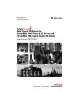
Figure P.2 shows multiple data nameplate locations for the drive. The data
and agency markings are different for equipment type. For example, the
complete drive is UL listed component; and the Power Modules are UL
recognized.
Figure P.1 Frame 2 Drive Data Nameplate Locations
SIDE VIEW
Complete Regenerative Drive
Output: 3 Phase, 0-400Hz
Made in the U.S.A. (FAC1C)
Nom. Coolant Pressure
20LC360N3ENNAN10WA
Input: 3 Phase, 47-63 Hz
MFD. in 2007 on JUL 05
Normal Duty Power
AC Voltage Range
Amps
Base Hz (default)
Continuous Amps
Rated Coolant
AC Voltage Range
Nominal Voltage
NEMA Type
Cat No.
Serial Number: MEAE2WJ0
Frame: 2
Original Firmware V. x.xxx
Series: A
FRONT VIEW (Cover Removed)

P-8 Overview
PowerFlex® 700L Liquid-Cooled Drive User Manual
Publication 20L-UM001D-EN-P
Frames 3A and 3B
Figure P.2 shows multiple data nameplate locations for the complete drive.
The data and agency markings are different for equipment type. For
example, except for 690V AC input, the complete drive is UL listed
component; and the Input Filter and Power Modules are UL recognized.
Base Power Module catalog numbers do not reflect the position 14 and
position 16 options actually installed inside the Inverter Power Module.
When ordering a replacement Inverter Power Module for use in a complete
drive, inform Rockwell Customer Service of both the Inverter Power
Module catalog string, and the position 14 and position 16 factory-installed
options shown on the Factory Installed Options label.
Figure P.2 Complete Frame 3A and 3B Drive Data Nameplate Locations
Inverter Power Module - Coupled With Converter
Nom. Coolant Pressure
Output: 3 Phase, 0-400Hz
20LE800N0NNNJND0LA
Inverter Power Module
Series: A
Original Firmware V. 2.005
20LE800N0NNNGNW0WA
Serial Number: MEAE2WJ0
Treated Water
Frame: 3B
Input: AC, 47-63 Hz
DC Voltage Range
DC Voltage Range
Base Hz (default)
P/N 181255-A01
Nom. Coolant Pressure
MFD. in 2005 on MAR 05
Rated Coolant
Continuous Amps
Output: DC
Amps
185 psig
N.A.
800
730-900
518-633
800
Normal Duty Power
Converter Power Module
UL Open Type/IP00
Nominal Voltage
Cat No.
600V
870HP
Input: DC
US
C
EN 50178
Production inspected
Type approved
Bauart gepruft
TUV
Rheinland
TUV
of North America
TUV Rheinland
Functional
Product Safety
Rheinland
TUV
Safety
MFD. in 2005 on MAR 05
P/N 181255-A01
DC Voltage Range
Base Hz (default)
AC Voltage Range
Amps
Continuous Amps
Rated Coolant
R
Cat No.
UL Open Type/IP00
Normal Duty Power
Nominal Voltage
US
C
TUV
TUV
Product Safety
Rheinland
Serial Number: MEAE2WJ0
of North America
TUV
Rheinland
TUV Rheinland
Frame: 3B
Treated Water
60 Hz
185 psig
800
0-600
800
730-900
EN 50178
Type approved
Bauart gepruft
Functional
Safety
Production inspected
Original Firmware V. 2.005
Series: A
870HP
600V
R
Complete Regenerative Drive
Output: 3 Phase, 0-400Hz
Made in the U.S.A. (FAC1C)
Nom. Coolant Pressure
20LE800ACENNA6DELA
Input: 3 Phase, 47-63 Hz
N.A.
Nom. Coolant Pressure
Serial Number: MEAE2WJ0
Frame: 3B
MFD. in 2005 on MAR 05
P/N 181255-A01
Type approved
TUV
Rheinland
Safety
MFD. in 2005 on MAR 05
P/N 181255-A01
Original Firmware V. 2.005
Series: A
20LE800N0NNNCNW0WN
Base Hz (default)
Rated Coolant
Continuous Amps
AC Voltage Range
Output: 3 Phase, 47-63 Hz
Input Filter Assembly
AC Voltage Range
Normal Duty Power
Nominal Voltage
Input: 3 Phase, 47-63 Hz
UL Open Type/IP00
Amps
Cat No.
870HP
518-633
N.A.
N.A.
800
518-633
800
600V
Production inspected
EN 50178
Bauart gepruft
Product Safety
TUV Rheinland
of North America
TUV
Functional
Rheinland
C
TUV
R
US
Normal Duty Power
AC Voltage Range
Amps
Base Hz (default)
Continuous Amps
Rated Coolant
AC Voltage Range
Nominal Voltage
NEMA Type 1/IP20
Cat No.
100 psig
Serial Number: MEAE2WJ0
TUV
Rheinland
Frame: 3B
Functional
Type approved
Safety
TUV
of North America
TUV Rheinland
Rheinland
Product Safety
Original Firmware V. 2.005
Series: A
N223
870HP
Treated Water
800
60 Hz
0-600
800
518-633
TUV
600V
EN 50178
Production inspected
Bauart gepruft
Ind. Cont.
Eq. 966X
US
C
Listed
R
Made in the U.S.A. (FAC1C)
Made in the U.S.A. (FAC1C)
Made in the U.S.A. (FAC1C)
Input
Filter Bay
Power
Module Bay
Inverter Power Module
Converter Power Module
Power Module Front,
Bottom Covers Removed
Input Filter Assembly
(Label on inside front of door)
Complete Regenerative Drive
(Label on inside front of door)
Power Module
Bay Door
Cutaway
NOTE: Power Module data nameplate labels
are duplicated on the exterior left side
wall of the Power Modules. These labels
may be viewed without removing the front,
bottom covers of the Power Modules.
Firmware
20-HIM-
20-COMM-
20B_-DB1-
20-I/O-
# :
Date:
HIM
I/O
COMM Module
Internal Dynamic Brake
Date:
# :
Firmware
FIELD INSTALLED OPTIONS

PowerFlex® 700L Liquid-Cooled Drive User Manual
Publication 20L-UM001D-EN-P
Chapter 1
General Installation Information
This chapter provides general information on mounting and wiring the
PowerFlex 700L Liquid-Cooled AC Drive.
Enclosure Ratings
PowerFlex 700L Liquid-Cooled AC drives have the following enclosure
ratings:
• Open-Chassis Style (IP00) - Frame 2: Intended to be installed in an
enclosure. Frame 3: Input filter and power modules, when purchased
individually, are intended to be mounted in an enclosure.
• Type 1 (IP20) - Frame 3: Drive is mounted in a separate NEMA/UL Type
1 enclosure to obtain this rating.
PowerFlex 700L Liquid-Cooled AC drives must be placed in an enclosure.
See the catalog string on page P-5
for fully assembled NEMA/UL Type 1
drive options.
AC Supply Source
Considerations
PowerFlex 700L Liquid-Cooled AC drives are suitable for use on a circuit
capable of delivering up to a maximum of 200,000 rms symmetrical
amperes. For the PowerFlex 700L Frame 3A or 3B complete drive, a circuit
breaker with shunt trip with the appropriate kAIC rating must always be
used upstream of the power module. See Table 1.A
for details.
PowerFlex 700L Liquid Cooled AC drives should not be used on undersized
or high-impedance supply systems. The supply system kVA should be equal
to or greater than the drive-rated kW, and the system impedance should be
less than 10%. Operation outside these limits could cause instability
resulting in drive shutdown.
System Impedance = (PowerFlex 700L kVA ÷ Transformer kVA) x Transformer % Impedance
The kVA of all PowerFlex 700L drives on the distribution system and the
system impedance of upstream transformers should be taken into account.
For information on ... See page ...
Enclosure Ratings
1-1
AC Supply Source Considerations 1-1
Power Wiring 1-4
CE Conformity 1-7
C-Tick Conformity 1-8
Using Input/Output Contactors 1-9
!
ATTENTION: To guard against personal injury and/or equipment
damage caused by improper circuit breaker selection, use only the
recommended circuit breakers specified in Table 1.A
.

1-2 General Installation Information
PowerFlex® 700L Liquid-Cooled Drive User Manual
Publication 20L-UM001D-EN-P
Unbalanced, Ungrounded or Resistive Grounded Distribution Systems
If phase-to-ground voltage will exceed 125% of normal or the supply
system is ungrounded, refer to Wiring and Grounding Guidelines for Pulse
Width Modulated (PWM) AC Drives (publication DRIVES-IN001) for more
information.
Input Power Conditioning
Certain events on the power system supplying a drive can cause component
damage or shortened product life. They are:
• The power system has power factor correction capacitors switched in and
out of the system, either by the user or by the power company.
• The power source has intermittent voltage spikes in excess of 6000 volts.
These spikes could be caused by other equipment on the line or by events
such as lightning strikes.
• The power source has frequent interruptions.
General Grounding Requirements
The drive Safety Ground - PE must be connected to system ground.
Ground impedance must conform to the requirements of national and local
industrial safety regulations and/or electrical codes. The integrity of all
ground connections should be periodically checked.
For installations within a cabinet, a single safety ground point or ground bus
bar connected directly to building steel should be used. All circuits
including the AC input ground conductor should be grounded
independently and directly to this point/bar.
!
ATTENTION: PowerFlex 700L Liquid Cooled Frame 2, Frame
3A, and Frame 3B drives contain protective MOVs and a
common mode capacitor that are referenced to ground. (The
protective MOVs and common mode capacitor in Frame 3A and
3B drives are mounted in the Input Filter Bay.) These devices
must be disconnected if the drive is installed on a resistive
grounded distribution system or an ungrounded distribution
system.
When installing a...
Refer to Ungrounded or Resistive
Grounded Installations on...
Frame 2 drive Page 2-11
Frame 3A or 3B drive Page 3-22

General Installation Information 1-3
PowerFlex® 700L Liquid-Cooled Drive User Manual
Publication 20L-UM001D-EN-P
Figure 1.1 Typical Grounding
Safety Ground - PE
This is the safety ground for the drive that is required by code. This point
must be connected to adjacent building steel (girder, joist), a floor ground
rod or bus bar (Figure 1.1
). Grounding points must comply with national
and local industrial safety regulations and/or electrical codes.
Shield Termination - SHLD
The Shield terminal provides a grounding point for the motor cable shield.
It must be connected to an earth ground by a separate continuous lead. The
motor cable shield should be connected to this terminal on the drive (drive
end) and the motor frame (motor end). Use a shield terminating or EMI
clamp to connect shield to this terminal.
When shielded cable is used for control and signal wiring, the shield
should be grounded at the source end only, not at the drive end.
Wiring Requirements for the Drive
Certain drive requirements should be checked before continuing with the
drive installation. Wire sizes, branch circuit protection, encoder feedback
(for FVC regulation), and wiring to disable the drive are all areas that need
to be evaluated.
Operation of the drive can be disabled in two locations. The Gate Enable
terminal block on the front of the power structure can be used to disable the
firing of inverter IGBTs. When the Gate Enable signal is opened, inverter
IGBTs are disabled independent of any software control. This action also
generates fault 207 in the Inverter Power Module to enunciate this
condition. As a result of this fault, the Active Converter Power Module is
also turned off, but this is done via software operation. The firing of IGBTs
in the Active Converter Power Module can be disabled independently of any
software control by opening the connection between terminals 13 and 14 on
the Active Converter Power Module control cassette PCB assembly
terminal block P1. This action also generates a fault in the Inverter Power
Module to enunciate this condition.
PE
R
(L1)
S
(L2)
T
(L3)
U
(T1)
V
(T2)
W
(T3)
DC
+
DC
–
Required
Input Fusing
Required Branch
Circuit Disconnect
BR1 BR2

1-4 General Installation Information
PowerFlex® 700L Liquid-Cooled Drive User Manual
Publication 20L-UM001D-EN-P
Input Line Branch Circuit Protection
Table 1.A AC Input Circuit Breaker Values
Power Wiring
Since most start-up difficulties are the result of incorrect wiring, take every
precaution to assure the wiring is correct. Read and understand all items in
this section before beginning installation.
Cable Types Acceptable for 400-690 Volt Installations
A variety of cable types are acceptable for drive installations. For many
installations, unshielded cable is adequate, provided it can be separated
from sensitive circuits. As an approximate guide, allow a spacing of 0.3
meters (1 foot) for every 10 meters (32.8 feet) of length. In all cases, long
parallel runs must be avoided. Do not use cable with an insulation thickness
less than or equal to 15 mils (0.4mm/0.015 in.). Use Copper wire only. Wire
!
ATTENTION: Most codes require that upstream branch circuit
protection be provided to protect input power wiring.
The PowerFlex 700L Frame 2 drive does not provide input power
short circuit protection. Specifications for the recommended fuse
or circuit breaker to provide Frame 2 drive input power protection
against short circuits are provided in Table A.F
and Table A.G.
Frame 3A and 3B complete drives include an input power circuit
breaker. The value of the circuit breaker provided with the drive is
listed in Table 1.A
.
Frame
Size
Input Voltage
Circuit Breaker
Provided
Shunt Trip
Rating
3A 400-480V AC 800 A 65 kAIC
575-690V AC 800 A 35 kAIC
3B 400-480V AC 1500 A 100 kAIC
575-690V AC 1500 A 35 kAIC
!
ATTENTION: The following information is merely a guide for
proper installation. Rockwell Automation, Inc. cannot assume
responsibility for the compliance or noncompliance to any code,
national, local, or otherwise for the proper installation of this
drive or associated equipment. A risk of personal injury and/or
equipment damage exists if codes are ignored during installation.
!
ATTENTION: National Codes and standards (NEC, VDE, BSI
etc.) and local codes outline provisions for safely installing
electrical equipment. Installation must comply with specifications
regarding wire types, conductor sizes, branch circuit protection,
and disconnect devices. Failure to do so may result in personal
injury and/or equipment damage.
/