Page is loading ...

CUSTOMER SERVICE PHONE: 1-800-426-8562
PREMISE™ SHAPES
Installation Instructions
Tools Required
Cross-recess (phillips head) screw driver
Level
Power Driver (optional)
Hex Head Driver
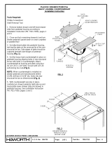
"L" Extension Assembly
1. Place the "L" extension top on a carpeted or
padded clean area of the floor with holes facing up.
2. Attach bracket(s) to end panels using two (2)
#10 x 1-1/2" flat head screws per bracket (Fig. 1).
NOTE: When another unit will be adjoining the oppo-
site side of end panel, center the bracket on the end
panel and use center two holes when attaching
bracket to end panel (Fig. 2).
3. Align bracket holes of 12" wide end panel with
predrilled holes located near edge on small exten-
sion of "L" extension top. Attach end panel using
four (4) #10 x 1" truss head screws (Fig. 3).
4. Align bracket holes of remaining end panel with
holes located near edge on long extension of "L"
extension top. Attach end panel to "L" extension top
using four (4) #10 x 1" truss head screws (Fig. 3).
5. CAUTION! Remove drawers from drawer
pedestal before attaching pedestal to underside of
"L" extension top. See page 2 of "Premise Drawer
Pedestal Installation Instructions" for drawer
removal.
6. Start four #10 x 1" hex head wood screws in the
pedestal mounting holes in "L" extension top, leaving
3/16" gap between surface of top and shoulder of
screw. Set pedestal housing on "L" extension top,
aligning key hole slots in pedestal housing with
screws in "L" extension top and slide pedestal
housing forward to engage screw necks in small
portion of key hole slots. Tighten screws (Fig. 4).
7. Place outer corner leg, (glide facing up and solid
wall toward outer corner) onto "L" extension top,
aligning holes in corner leg bracket with predrilled
holes located near outer corner of top. Attach outer
corner leg to top using four (4) #10 x 1-1/2" pan head
screws (Fig. 5).
FIG.1
FIG.2
#10 X 1-1/2"
FLAT HEAD
SCREWS
FIG.3
FIG.4
#10 X 1"
TRUSS HEAD
SCREW (4)
#10 X 1"
HEX HEAD
SCREW (4)
FIG.5
#10 X 1-1/2""
PAN HEAD
SCREW (4)
KEY HOLE
SLOT (4)
3/16" GAP
BETWEEN
SURFACE OF TOP
AND SHOULDER
OF SCREW
END PANEL LOCATION
FOR "D" EXTENSION
ASSEMBLY
Part No: Rev.Page:
E.C.O. No: 263-159 1 of 2 7021-6872 A

Part No: Rev.Page:
E.C.O. No:
"D" Extension Assembly
1. Place the "D" extension top on a carpeted or
padded clean area of the floor with holes facing up.
2. Attach brackets to end panels using two (2)
#10 x 1-1/2" flat head screws per bracket (Fig. 1).
NOTE: When another unit will be adjoining the
opposite side of end panel, center the bracket on the
end panel and use center two holes when attaching
bracket to end panel (Fig. 2).
3. Attach 12" end panels to the "D" extension top:
Align holes in end panel brackets with predrilled
holes located near edges of "D" extension top and
attach using four (4) #10 x 1" truss head screws per
end panel (two screws per bracket) (Fig. 3).
4. Position modesty panel(s) between end panels.
Align slots in modesty panels with predrilled holes in
end panels. Use two (2) # 10 x 3/4" pan head
screws to attach each end of a modesty panel to the
end panel (Fig. 8).
5. Position dual-leg base on "D" extension top,
aligning holes in base brackets with pre-drilled holes
in top. Attach base to top using eight (8) # 10 x 1"
trusshead screws (Fig. 9).
6. Turn assembled unit right-side up and level the
unit as required.
263-159 2 of 2 7021-6872 A
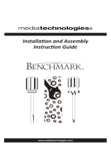
8. Slide the inner corner leg down into outer corner
leg. Align holes in inner corner leg with holes in tab
of outer corner leg nearest underside of "L" exten-
sion top. Fasten corner legs together using four
(4) #10 x 3/8" screws, two (2) at each end (Figs. 6
and 7).
9. Position the shorter two modesty panels
between the 12" wide end panel and the corner leg
assembly, aligning slots in the sides of each modesty
panel with holes in corner leg assembly and holes in
end panel. Use two (2) # 10 x 3/4" panhead screws
to attach each modesty panel to the end panel. Use
two (2) # 10 x 3/8" panhead screws to attach each
modesty panel to the corner leg assembly. Screw(s)
must be aligned through holes in both the inner and
outer corner leg (Fig. 8).
10. Similarly, attach the longer modesty panels be-
tween remaining end panel and corner leg assembly.
11. Turn assembled unit right-side-up. Level the
unit and re-install pedestal drawers as instructed in
"Drawer Pedestal Installation Instructions".
FIG. 6
#10 X 3/8" SCREW
(2) AT EACH END
FIG. 8
INNER LEG
ALIGN HOLES IN
INNER AND OUTER
CORNER LEGS
FIG. 7
MODESTY
PANEL(S)
#10 X 3/8"
PAN HEAD
SCREW
#10 X 3/4"
PAN HEAD
SCREW
FIG. 9
#10 X1"
TRUSS HEAD
SCREW (8)
/