Page is loading ...

These instructions cover the assembly and
installation of both the return and the bridge.
The return may be attached to either a desk or a
corner unit (Figs. 1 and 2).
The bridge spans between two desks or a desk and
a corner unit (Figs. 3 and 4).
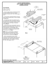
Tools Required
Cross-recess (Phillips) screw driver
Level
Power driver (optional)
Hex head driver
Return Assembly
1. Place the return top on a carpeted or padded
clean area of the floor with the holes facing up.
2. Attach brackets to end panels using two (2)
#10 x 1-1/2" flat head screws per bracket (Fig. 5).
3. Align bracket holes of end panel with pre-drilled
holes in top. Attach end panel using four (4)
#10 x 1" truss head screws (Fig. 6).
4. CAUTION: Remove drawers from drawer
pedestal before attaching pedestal to underside of
return top. See page 2 of "Premise Drawer Pedestal
Installation Instructions" for drawer removal.
5. Start four (4) # 10 x 1" hex head screws in the
pedestal mounting holes in the return top, leaving
3/16" gap between the surface of the top and
shoulder of the screw. Set pedestal housing on
return top, aligning key hole slots in pedestal
housing with screws in return top and slide pedestal
housing forward to engage screw necks in small
portion of key hole slots. Tighten screws (Fig. 7).
RETURN
RETURN
BRIDGE
BRIDGE
FIG. 1
FIG. 2
FIG. 3
FIG. 4
6. See "Attaching Returns to Adjacent Units" section of
this installation instruction. Turn return over, supporting
overhanging portion of top and attach to adjoining unit
and level.
263-168 1 of 2 7021-6754 C
Part No: Rev.
Page:
E.C.O. No:
CUSTOMER SERVICE PHONE: 1-800-426-8562
PREMISE™ RETURN / BRIDGE ASSEMBLY
Installation Instructions
FIG.5
#10 X 1-1/2"
FLAT HEAD
SCREWS
FIG.7
#10 X 1"
HEX HEAD
SCREW (4)
KEY HOLE
SLOT (4)
3/16" GAP
BETWEEN
SURFACE OF TOP
AND SHOULDER
FIG. 6

7. After the return top is attached to adjoining unit and
leveled, position the modesty panels between the return
end panel or pedestal drawer and the end panel of the
adjoing unit. Using the modesty panel as a template for
the adjoining unit, drill two (2)7/64" holes in end panel for
each modesty panel (Fig. 8).
8. Attach each modesty panel to end panels using
two (2) #10 x 3/4" screws per side. Attach modesty
panel(s) to pedestal drawer unit using two (2)
#10 x 3/8" screws (Fig. 8).
2. Adjust the glides on the adjacent unit to level it.
Set the return in place by resting the open end of the
return on the return support bracket. Slide the return
top so that it is tight against the adjacent unit top.
3. Fasten the return to the support brackets using
#10 x 1" pan head screws provided (Fig. 10).
4. Adjust glides to level the return. Top surfaces of
adjoining units must be in alignment.
Attaching a Machine Height Return to an
Adjacent Unit
NOTE: Machine height returns may be attached to
desk units only.
1. Fasten drop mount brackets to underside of the
return, aligning holes in bracket with pre-drilled holes
in the return. Use four (4) #10 x 1" pan head screws
provided per bracket (Fig.11).
2. Set the return iin place below the desk unit.
Attach drop mount brackets to desk unit using C-
clamps as shown. Take care not to mar the top
surface of desk (Fig.12).
3. Adjust the glides to level each unit.
4. Spot screws through bracket holes and drilll
four (4) 5/32" dia. x 1" deep holes per bracket.
5. Fasten drop mount bracket to desk unit with
four (4) # 10 x 1" pan head screws.
6. Remove C-clamps.
Attaching a Bridge to an Adjoining Unit
Bridges are intended to span between two single
pedestal desks (attaching to the desks on the side
opposite the pedestal), or a combination of a single
pedestal desk and a corner unit
(Figs. 3 and 4, page 1).
Four flat brackets have been provided for attaching
the bridge to adjacent units. Use two (2) brackets on
a bridge end being attached to a desk. Use (1)
bracket on a bridge end being attached to a corner
unit.
1.Install the flat brackets on the adjoining units using
four (4) screws per bracket. Do not completely tighten
screws at this time.
2.Set the bridge on the brackets between the two
adjacent units.
3.Align holes in underside of bridge with holes in
brackets. Attach bridge to brackets using four (4)
screws per bracket. Do not completely tighten screws
at this time.
4.Square and level all units.
5.Tighten screws completely.
6.Using the template provided, mark the modesty
panel hole locations in the end panels. Modesty
panel(s) is located as shown (Figs. 3 and 4).
Attaching Returns to Adjacent Units
Attaching a Desk Height Return to an
Adjacent Unit
The desk height return may be attached to either a desk
unit or a corner unit.
1. Fasten return support brackets to the predrilled
underside of the adjacent unit top, using four (4)
#10 x 1" pan head screws provided (Fig. 9).
263-168 2 of 2 7021-6754 C
Part No: Rev.
Page:
E.C.O. No:
USE HOLES IN MODESTY PANEL AS
GUIDE TO DRILL HOLES IN EDGE OF
END PANEL OF ADJOINING UNIT
MODESTY
PANEL(S) #10 X 3/8"
PAN HEAD
SCREW
#10 X 3/4"
PAN HEAD
SCREW
FIG. 8
DESK END
PANEL
UNDERSIDE OF
RETURN TOP
UNDERSIDE OF
DESK TOP
FIG. 10
UNDERSIDE OF
RETURN
UNDERSIDE OF
DESK
DESK
END PANEL
FIG. 9
FIG. 11
UNDERSIDE
OF RETURN
FIG. 12
UNDERSIDE OF
DESK
UNDERSIDE OF
RETURN
/