Page is loading ...

BVD-407x
BVD-407x VIZIT
BVD-407x
CVB
RT
FEATURES
BVD-407x
VIZIT-M430C VIZIT -M460CM
VIZIT-ML300 -ML400
SPECIFICATIONS
V 17...25
W4
80
1
mm 95 x 150 x 37
kg 0.4
BVD-407RVB/TVB BVD-407RCB/TCB - 30 + 45C
98% + 25C
VIZIT-RF2
VIZIT-TM
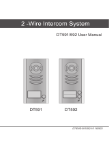
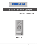
Doorstation is intended for use in videodoorphones of 400-series.
The following models of are available:
Abbreviations used in the models names:
- Colour camera; - B/W Camera; - Board lens;
- RFID reader for RF-keys ; - TM-button reader for TM-keys reader.
Cameras parameters are given below:
a (up to 80 seconds)
Doorstation is intended for joint operation with:
- Monitors , or similar;
- Electromagnetic lock , .
Operating voltage,
Max. power consumption,
Max. number of keys
Master key
Unlocked state duration, sec 1 to 12 (programmable)
Door lock control MOSFET
Dimensions,
Weight,
Ambient temperature range
...
Relative humidity of air up to at
Only keys (125 KHz ) are supported.
Only keys (DS1990A/ iButton® from Dallas Semiconductor) are supported.
·
·
·
·
·
·
·
·
·
·
-,
Intercom between visitor and subscriber
Door zone videomonitoring
Illumination for the camera
The entrance door unlocking:
- by applying RF- or TM-keys
- by pressing the button on a monitor during intercom
- by pressing the indoor button
Voice menu and messages during programming and work
Programmable volume of intercom and service messages
Programmable unlocked state duration
Programmable lock type (electro-magnetic or -mechanical)
Memorizing and erasing of RFID and TM codes
A beep at a monitor while its key used
DOOR OPEN
EXIT
MODEL B/W
camera with
Board lens
BVD-407RVB
BVD-407RСB
READER Colour
camera with
Board lens
Illumination
for
the camera
BVD-407TVB
BVD-407TСB
RFID TM-
button
Parameter
Lens
Angle of view (diagonal),°
uColo r system
Scanning system
Resolution, TVL
Output voltage,
Vpp @ 75 Ohm
Minimum illumination of an
object at 50 cm distance
from the camera, Lux
Model name
BVD-407RCB,
BVD-407TCB
BVD-407RVB,
BVD-407TVB
“Board”
PAL
CCIR (EIA-optional)
CCIR
0.1
1 ± 0.15
-
³120

PARTS LIST
BVD-407x 1
1
1
1
SAFETY INSTRUCTIONS
25 VDC
INSTALLATION
ATTENTION!
BVD-407x
ATTENTION! min. 10 Ohms.
min. 20 Ohms.
Doorstation pс.
Mounting kit pс.
Operating instruction pс.
Package pс.
The rest of equipment needed for videodoorphone system is available upon request.
The doorstation does not contain voltage above .
Do not make any connections or repair when the power is on.
Connect the grounding wire of the doorstation to the protective ground.
To maximize the reliability of this product, do not expose it to rain, snow or direct sun rays!
Before mounting, examine carefully the operating instruction for the installation order and wiring diagrams.
Mounting dimensions are shown on Figure 1 in millimeters.
The doorstation center should be approximately 1.5 meters above the floor.
Fix the doorstation on a door (Figure 2), using the screws and concrete inserts from the mounting kit.
Drive the gags into mounting holes.
Use 75-Ohm coaxial cable for video circuits to reduce external noises influence on image.
Fix the coaxial cable to back lid by means of a shackle.
Electromechanical lock impedance should be
Electromagnetic lock impedance should be
If an electromechanical lock is used, connect a damper diode (50V/1A, not supplied) to lock terminals.
Figure 1 ounting dimensions- BVD-407 m
8 79
95
8134
150
12,5 70
13
124
29
37

FUNCTIONAL CHECK
PROGRAMMING
1. Lock type
ML
EL
2. Unlocked state duration (1 to 12 seconds)
3. Volume of messages (Minimum / Medium / Maximum)
Medium
Athe
the Adjust brightness, contrast and colour, if needed.
There are two modes of programming: system setup and service settings.
Electromagnetic lock ( ) is released when voltage across its terminals is switched off.
Electromagnetic lock is set by default.
Electromechanical lock ( ) is released when voltage across its terminals is switched on.
Default setting is 7 seconds.
1 second is recommended for electromechanical lock.
Default setting is
System setup
Before switching the power on verify all electric connections.
Turn the power supply on. The lamps illuminate on each side of the camera.
Press the button on the doorstation - a beep sounds at apartment monitor while the button remains
pressed, image appears on screen.
Pick up the handset and check duplex intercom. Hang up the handset when finished.
=
=
Figure 2 - Doorstation wall-mounting

4. MASTER - key memorizing
1. Keys memorizing
2. Erasing of keys
3. Erasing of keys
Entering into programming and all available system setup and service settings transitions are shown on
Figures 5 - 7.
To enter programming mode:
DOOR OPEN
“Programming is finished”
To change the doorstation volume:
Apply the Master-key in Intercom mode
ABBREVIATIONS
The MASTER - key enables easy entering into programming and doorstation volume adjustment.
- Pick up the handset of the monitor and check duplex intercom.
- Press the button on the monitor 7 times.
Each time hold the button until a beep.
- After the screen switches off, hang up the handset.
- The doorstation produces beeps and enables Voice MENU. Follow Menu messages to perform service settings and
system setup. Setup and settings contents, function and order are given in part “Programming”.
-After the programming is complete, press the button.
sounds and the doorstation returns into stand-by mode.
You can enter programming mode using the MASTER-key memorized during the first programming.
- for more than 5 seconds. Press or
the volume by one step. The number of step is pronounced.
9 steps are available.
Press again, if needed. Hang up the handset when finished.
LN Intercom line VO VIDEO OUT
GND GROUND VG VIDEO GROUND
+E Power for doorstation LC Lock Control
Ec Power for built-in camera OP OPEN
Service settings
being applied to the reader
all
A
A
A
once to decrease twice
to increase
Figure 3 - Doorstation with monitorBVD- 7x VIZIT-M430C
and electromechanical lock
40
-18
+18
+12
-12
50 V
1A
Power supply
BPD18/12-1-1
LN-
GND
LN+
VI1
+E
DATA
Ec1
Ec2
GND
VI2
Monitor
VIZIT-M430C
1
2
3
4
5
1
2
2
1
1
2
12
2
1
A
B
C
D
1
2
3
4
6
12
25 50 100
0.2 0.4 0.8
0.8 1.5
Min. cross-sections
of wires, mm2
Length
of cables
0.4
A+B
C+D
meters
Doorstation
BVD-407x
LN
GND
+E
Ec
LC
VO
VG
6
5
OP

Figure 4 - Doorstation with monitor
and button
BVD- 7x VIZIT-M430C,
VIZIT-ML400 “EXIT 300”
40
LN-
GND
LN+
VI1
+E
DATA
Ec1
Ec2
GND
VI2
Monitor
VIZIT-M430C
6
2
3
4
5
2
2
1
1
B
1
3
5
4
6
1
2
A
D
C
Electromagnetic lock
VIZIT-ML400
1
Red
Green
White
Black
Blue
Button
“EXIT 300”
25
0.2 0.4
0.8
Min. cross-sections
of wires, mm
Length of
cables
0.4
A+B
C+D+E
meters
50
2
112
-18
+18
+12
-12
Power supply
BPD18/12-1-1
Doorstation
BVD-407x
LN
GND
+E
Ec
LC
VO
VG
OP
2
1
3
3
2
E
Figure 5 - Transitions between
system setupservice settings and
Power on
7
DOOR OPEN
strokes on the
button
of a monitor
in intercom mode
Apply the MASTER - key
for more than seconds5
3long beeps
Service settings
4strokes on
or apply the MASTER-key
A
4strokes on
or apply the MASTER-key
A
2long beeps
System setup
3short beeps
Stand-by mode
Press & hold
> sec to quit
programming
1
A

1
Lock t
stroke on
ype
A
System setup
Beep 1EL
2ML
-
-
stroke
strokes
2strokes
Unlocked state
duration
Beep
1-stroke
minimum volume
3strokes
Volume of
messages
Beep
4strokes or the MASTER - key
Transition to service settings
Service settings
Programming
is finished
1...12
seconds
strokes
number of strokes =
unlocked state
duration in
(
)
2-strokes
medium volume
3-strokes
maximum volume
Press & hold
> sec to go back1
A
Press & hold > sec
to quit programming
1A
6
MASTER - key
memorizing
strokes
Beep Apply a key
to be the MASTER-key
which is
Figure 6 - Transitions in system setup mode
Figure 7 Transitions in service settings mode-
1
Memorizing of keys
stroke on A
Beep
“Done” or
“Error” sounds
“Done” or
“Error” sounds
Apply a key
to be memorized
Apply a key
to be erased
2
Erasing of key
being applied
strokes
Beep
Countdown - 10 sec.
Press once
for exit
without erasing
A
3strokes
Erasing of all keys
Beep
4strokes or MASTER-key
system setupTransition to
Press and hold > sec
to quit programming
1A
System setup
Programming
is finished
Service settings
Press & hold
> sec to go back1
A
Press & hold
> sec to go back1
A

OPERATION
Note: The door can be unlocked without picking up the handset
videomonitoring
Press the - button on the doorstation. Acall rings at the monitor.
Pick up the handset and check duplex intercom.
Press the DOOR OPEN button. The door unlocks for the set time. “Come in, please!” sounds, then intercom
continues.
Hang up the handset. The system goes into Stand-by mode.
.
Press the DOOR OPEN button when a call comes. The door unlocks. “Come in, please!” sounds,
then the system goes into Stand-by mode.
Check operation of all keys. If the applied key is memorized, the door unlocks, “Come in, please!” sounds at
the doorstation, and a short beep sounds at the monitor. If the applied key is not memorized, the door remains
locked, and “Sorry, access denied!” sounds.
Press the EXIT 300 button to release the lock from the inside.
The door unlocks for the set time, “A door is open” sounds.
During intercom is disabled.
Press the MONITOR button to activate mode (refer to the monitor operating instruction for
details).
Pick up the handset during videomonitoring to activate intercom with the doorstation.
A
key usage and lock release signalling
/