Page is loading ...

The design and specifications can be changed without notice to users.
Copyright of this manual is reserved.
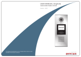
VIDEO DOOR PHONE SYSTEM
USER MANUAL (English)
Item No. : 13535, 13536
Version2.0.1.1.12.01

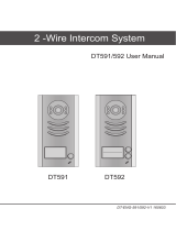
Camera Lens
Speaker
-1-
CONTENTS 1. Parts and Funcons
Touch Sensive
Digital Keypad
Nameplate
Call Buon
Microphone
Rainy GuardSide View90mm
176mm
23mm
Rainy Guard
Side View
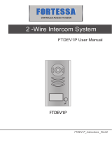
Camera Lens
Touch Sensive
Digital Keypad
Speaker
Nameplate
Call Buon
Microphone
119mm
220mm
Screws for panel
mounng
1.1 Door Staon E
1.2 Door Staon F
1. Parts and Funcons - - - - - - - - - - - - - - - - - - - - - - - - - - - - - 1
2. Mounng and Seng - - - - - - - - - - - - - - - - - - - - - - - - - - - - 2
2.1 Door staon Mounng - - - - - - - - - - - - - - - - - - - - - - - - 2
3. Terminal Descripons - - - - - - - - - - - - - - - - - - - - - - - - - - - 5
4. System Wiring and Connecons - - - - - - - - - - - - - - - - - - - - 6
4.1 Basic Connecon - - - - - - - - - - - - - - - - - - - - - - - - - - - - 6
4.2 Electric Lock Connecon - - - - - - - - - - - - - - - - - - - - - - - 6
4.3 Electromagnec Lock Connecon - - - - - - - - - - - - - - - - - 7
4.4 Mul Door Staons Connecon - - - - - - - - - - - - - - - - - - - 9
4.5 Mul Monitors Connecon - - - - - - - - - - - - - - - - - - - - - - 10
5. DIP Switches Seng - - - - - - - - - - - - - - - - - - - - - - - - - - - - - - -11
5.1 DIP Switches Sengs of Doorstaon - - - - - - - - - - - - - - -11
5.2 DIP Switches Sengs of Monitor - - - - - - - - - - - - - - - - - -11
6. ID Card Registraon - - - - - - - - - - - - - - - - - - - - - - - - - - - - - -12
6.1 Introducon - - - - - - - - - - - - - - - - - - - - - - - - - - - - - - - - - 13
6.2 Add User Cards - - - - - - - - - - - - - - - - - - - - - - - - - - - - - - 12
7. Unlock Operaons - - - - - - - - - - - - - - - - - - - - - - - - - - - - - - - - 14
7.1 Unlocking user code - - - - - - - - - - - - - - - - - - - - - - - - - - - - - 14
8. Precausons - - - - - - - - - - - - - - - - - - - - - - - - - - - - - - - - - - - - 15
9. Specificaons - - - - - - - - - - - - - - - - - - - - - - - - - - - - - - - - - - 15

-3--2-
2. Mounng and Seng
2.1 Door Staon Mounng
Door Staon E Mounng Door Staon F Mounng
Adjust camera angle
1 2
43
Drill holes in the wall to match the size of
screws and aach the rainy guard to the wall.
Aach the panel to the rainy guard. Use the screwdriver and the screw to fix
the panel.
Connect the cable correctly and adjust
camera to the right angle.
Adjust
camera angle
1 2
43
Drill holes in the wall to match the size of
the mounng box and aach it to the wall.
Aach the panel to the mounng box and
use supplied screws to fix the panel.
Place name label.
Connect the cable correctly and adjust
camera to the right angle.

-4- -5-
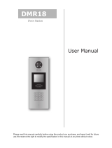
3. Terminal Descripons
MIC adjustment
SPK adjustment
1 2 3 4
ON DIP
Lock Control Jumper
Doorstaon Code DIP
3 2 1
BUS
PL
S1+ S2+ S-
Main Connect Port
• Lock Control Jumper: To select the lock type: see secon 5
• Doorstaon Code DIP: It supports total 4 door staons,see secon 6
• MIC: Adjust the volume of Microphone
• SPK: Adjust the volume of Speaker
• Main Connect Port: To connect the bus line and the electronic locks.
• BUS: Connect to the bus line, no polarity.
• PL: External lock power input, connect to the power posive(power +).
• S1+, S2+: Lock power(+) output, to connect 2 locks.
• S-: Lock power(-) output, connect to the power(-) input of locks(only when using the camera to power the
locks, if using the external power supply for the locks, the S- should not be connected).
2.3 Adjusng Camera Angle
2.2 Placing Name Label
Move the plasc cover away to
open the transparent name label
cover, insert name paper, then
put the plasc cover back to the
panel.
Use a screwdriver to loosen the
screw and adjust the angle for
the camera, then fix the screw.

Connect two lock
Jumper posion in 2-3
4. System Wiring and Connecons
4.1 Basic Connecon
4.2 Electric Lock Connecon
-
+
AC~
Monitor
DPS PS4
L1 L2 PL S1+ S2+ S-
EB
*
LOCK
BUS PL S1+ S2+ S-
LOCK
2nd
1ST
2nd
EB
*1ST
1 2 3
EB
*
LOCK
BUS PL S1+ S2+ S-
Connect one lock
Jumper posion in 2-3
1 2 3
Note:
1. Only applicable to the power on to unlock type of electronic locks.
2. The door lock is limited to 12V, and holding current must be less than 250mA.
3. The door lock control is not med from Exit Buon(EB).
4. The Unlock Mode Parameter of Monitor must be set to 0 (by default).
4.2.1 Door Lock Controlled by Internal Power
4.3 Electromagnec Lock Connecon
Note:
1. Only applicable to the power off to unlock type of electronic locks.
2. The door lock is limited to 12V, and holding current must be less than 250mA.
3. The door lock control is not med from Exit Buon(EB).
4. The Unlock Mode Parameter of Monitor must be set to 0 (by default).
4.3.1 Door Lock Controlled by Internal Power
Connect one lock
Jumper posion in 2-3
1 2 3
EB
*
LOCK
BUS PL S1+ S2+ S-
Normally closed
Connect two lock
Jumper posion in 2-3
EB
*
LOCK
LOCK
2nd
1ST
2nd
EB
*
1ST
1 2 3
BUS PL S1+ S2+ S-
Note:
1. The external power supply must be used according to the lock.
2. The inside relay contact is restricted to AC or DC 24V/3A.
3. The jumper must be taken off before connecng.
4. Setup the Unlock Mode of Monitor for different lock types.
• Power-on-to-unlock type:Unlock Mode=0 (by default)
• Power-off-to-unlock type:Unlock Mode=1
4.3.2 Door Lock Controlled by Dry Contact
Connect two lock
Take off the Jumper
1 2 3
BUS PL S1+ S2+ S-
LOCK
LOCK
POWER
SUPPLY
LOCK
BUS PL S1+ S2+ S-
POWER
SUPPLY
Connect one lock
Take off the Jumper
1 2 3
-7--6-

monitor
intercom
setup
exit
Outdoor Tone -- 01
Intercom Tone -- 05
Monitor Time -- 1min
Advanced Set...
Auto Record -- OFF
Exit
0
* * *
Password:
Slave Addr Set -- 0
Guard Unit Set -- 0
Date/Time Set...
Other Settings...
Information...
Exit
Hardware ver 0302
Software ver 0168
Voltage 22.4V
Manufacture 00.0T
Restore to default
Exit
Unlock Time 1
Unlock Mode 0
Exit
1. Press
setup
setup item
on main menu page.
2. Select Advanced Set...
password is required.
4. Select Informaon.. 5. Press UNLOCK buon
and hold for 2s.
6. Seng unlock mode to
0 or 1.
3. The default password is
2008.
-9--8-
4.3.3 Unlock parameter seng(set in monitor)
4.4 Mul Door Staons Connecon
Note:
1. Must connect DT596 correctly before seng.
2. The parameter will be saved in DT596 automacally,so you only need to set one monitor.
3. The above cutline is fit for T107 series monitors only,for T753,T863 series monitors,please refer to the
corresponding user manuals.
1# Camera
85~260VAC
DPS PS5
Monitors
L1 L2 PL S1+ S2+ S- L1 L2 PL S1+ S2+ S-L1 L2 PL S1+ S2+ S-L1 L2 PL S1+ S2+ S-
123 4
ON
123 4
ON
123 4
ON
123 4
ON
ID=00
ID=10
ID=01ID=11
2# Camera3# Camera4# Camera

5. DIP Switches Seng
-11--10-
4.5 Mul Monitors Connecon 5.1 DIP Switches Sengs of Door Staon
5.2 DIP Switches Sengs of Monitor
Basic IN-OUT Wiring Mode ON(1)
=
OFF(0)
=
ON
ON
123 4
ON
123 4
ON
123 4
ON
123 4
ON
123 4
ON
123 4
ON
Total 4 bits on the DIP switches can be configured.The switches can be modified either before or aer installaon.
Seng Item Bit State Descripons
Bit1 and Bit2
(it is used to set
the ID code for
door staon)
Default seng, ID = 0(00), set to the first Door Staon.
ID = 1(10), set to the second Door Staon.
ID = 2(01), set to the third Door Staon.
ID = 3(11), set to the fourth Door Staon.
Bit3
Bit4
Acvate external output seng,the relay 2 terminal doesn't
respond to the second lock and will be closed for 60 seconds
when the "Lockout" is carried out.The alarm connected to
the terminal of relay 2 will be acvated.
inacvate
Reserve
There are 6 bit switches in total. The DIP switches are used to configure the User Code for each Monitor.
Bit-6 is line terminal switch, which needs to be set to ON if the Monitor is in the end of the bus, otherwise set to OFF.
Bit state Seng Bit state Seng
1 2 3 4 5 6
ON
1 2 3 4 5 6
ON
The monitor is
not at the end
of the bus.
The monitor is
at the end of
the bus.
Code=0, DIP-6=off
Code=14, DIP-6=off
Code=15, DIP-6=on
1 2 3 4 5 6
ON
1 2 3 4 5 6
ON
1 2 3 4 5 6
ON
monitor
monitor
monitor
123 4
ON
ID=00
85~260AC
DPS PS5
Aenon: You must follow the dip switch sengs in the table on page 12.
So, 1st monitor all switches down, 2nd monitor switch 1 up, 3rd monitor
switch 2 up, etc.

Bit-1 to Bit-5 are used for User Code seng.The DT596 responds to 0~15 .
6.2.1 Control one lock (the first lock)
-13--12-
6. ID Card Registraon
BIT STATE USER CODE BIT STATE USER CODE BIT STATE USER CODE
Code=0 Code=6 Code=11
Code=1 Code=7 Code=12
Code=2 Code=8 Code=13
Code=3 Code=9 Code=14
Code=4 Code=10 Code=15
Code=5
1 2 3 4 5 6
ON
1 2 3 4 5 6
ON
1 2 3 4 5 6
ON
1 2 3 4 5 6
ON
1 2 3 4 5 6
ON
1 2 3 4 5 6
ON
1 2 3 4 5 6
ON
1 2 3 4 5 6
ON
1 2 3 4 5 6
ON
1 2 3 4 5 6
ON
1 2 3 4 5 6
ON
1 2 3 4 5 6
ON
1 2 3 4 5 6
ON
1 2 3 4 5 6
ON
1 2 3 4 5 6
ON
1 2 3 4 5 6
ON
1. Up to 1000 user cards can be registered to the door staon.
2. Easy management with LED status and sound hints.
3. There are two master cards, one MASTER CARD ADD card and one
MASTER CARD DELETE card, When registerening new master cards,
the old master cards will be invalid automacally.
4. Card reading distance is from 3 to 5 cm.
5. The master cards are necessary when you add or delete user cards.
Please keep it well for future use.
6.1 Introducon:
6.2 Add User Cards:
Show the MASTER CARD
ADD card to ID card window
in standby mode.
beep+,beep
red
(on) (off)
blue
Show the MASTER CARD
ADD card to exit.But it will
return to standby mode if no
operaon within 15s.
beep,beep+
red
(off) (off)
blue
Show user cards to be
added, one by one.
beep+
red
(blink) (off)
blue
6.2.2 Control two lock
Show the MASTER CARD
ADD card to ID card window
in standby mode.
beep+,beep
red
(on) (off)
blue
Show the MASTER CARD
ADD card to exit.But it will
return to standby mode if no
operaon within 15s.
beep,beep+
red
(off) (off)
blue
Press "CALL" buon.
At the same me, show
user cards to be added,
one by one.
beep+
red
(blink) (off)
blue
6.2.3 Delete User Cards:
Show the MASTER CARD
DELETE card to ID card
window in standby mode.
beep+,beep
red
(off) (on)
blue
Show the MASTER CARD
DELETE card to exit.But it
will return to standby mode
if no operaon within 15s.
beep,beep+
red
(off) (off)
blue
Show user cards to be
deleted in sequence.
beep+
red
(off) (blink)
blue
6.2.4 Access Inializaon (delete all user cards):
Show the MASTER CARD
DELETE card to ID card
window in standby mode.
beep+,beep+
red
(off) (on)
blue
Show the MASTER CARD
ADD card to ID card window
again, format operaon is
performing.
beep, beep,
beep, beep,
beep+
red
(off) (off)
blue
Show the MASTER CARD
ADD card to ID card window.
beep+
red
(on) (on)
blue

• Please clean the unit with so coon cloth, don't use the organic impregnant or chemical clean agent.
If necessary, please use a lile pure water or dilute soap water to clean the dust.
• The unit is weather resistant. However do not spray high pressure water on access control keypad directly.
Excessive moisture may cause problems with the unit.
• You must use the right adaptor which is supplied by the manufacture or approved by the manufacture.
• Pay aenon to the high voltage inside the products, please refer service only to a trained and qualified
professional.
8. Precausons
• Power Supply : DC 24V (supplied by PS4-24V or PS5-24V)
• Power Consumon : Standby 60mA; Working status 200mA
• Camera : Pinhole Sharp Color CCD; 420 TV Lines
• Lock Power Supply : 12Vdc, 300mA(Internal Power)
• Number of relay circuits : 2
• Mounng : Surface mounng(DT596/ID), Flush mounng (DT596F/ID)
• Working temperature : -10ºC ~ +45ºC
• Wiring : 2 wires,non-polarityC
• Dimension: 176(H)×90(W)×28(D)mm(DT596/ID), 220(H)×119(W)×52(D)mm(DT596F/ID)
9. Specificaons
-15--14-
• If an authorized user card is being shown the buzzer will sound of beep+,
and the LED indicator will light up.
• If the unauthorized user card is being shown, the buzzer will sound of beep 3 mes.
Show the MASTER CARD
ADD card to ID card window
in standby mode.
beep+,beep
red
(on) (off)
blue
Show the MASTER CARD
ADD card to exit.But it will
return to standby mode if no
operaon within 15s.
beep,beep+
red
(off) (off)
blue
Show user cards to be
added, one by one.
beep+
red
(blink) (off)
blue
6.2.5 Authorize master cards:
By default,there are two master cards marked MASTER CARD ADD and MASTER CARD DELETE, but you
should know that the master card can be authorized by users at any me. That means any two user cards
can be authorized to master cards, when registered new master cards, the old master cards will be invalid
automacally.
7. Unlock Operaons
When the registered user card has been shown to ID card window, the LED indicator (the first lock : red ;
the second lock : blue) lights up, the buzzer sounds, and the electric door strike will be unlocked.
Note 1 : if the user card controls one lock only,show the user card to release the first lock.red indicator lights up.
Note 2 : if the user card controls two locks,show the user card to ID card window in standby mode,the red & blue
indicator flashes for 1.5s alternately.During this me,press "CALL" buon to release the second lock.
Otherwise, release the first lock if there isn't any operaon within 1.5 seconds.
• If 10 mes unauthorized access cards are connuously aempted, the release funcon will be forbidden
and the showing card operaon will be disabled for 60 seconds.
• If the DIP3 switch is set to 1 and the relay 2 doesn't respond the second lock, in which when showing
user cards controlling two locks or when pressing unlock 2nd on monitor, the monitor, the second lock
whouldn’t release. At this point, aer to 10th aempts of showing access card, relay 2 will be closed for
60 seconds and the buzzer will connuously sound about 8 mes, if the system is connected to thr alarm,
the alarm funcon will be acvated.
7.1 Unlocking ID Card
Example: Release the first lock
Red LED lights up
(During relay 1 operaon)
beep+
red
(on) (off)
blue
Example: Release the second lock
Red LED lights up
(During relay 2 operaon)
beep+
red
(off) (on)
blue
• You can acvate the electric door strike by pressing the request to exit buon connected to the unit.
Pressing request to exit buon 1 releases relay 1, and pressing request to exit buon 2 releases relay
2.(The unlock funcon will work when the request to exit buon is being pushed, even while the
proximity access is forbidden.
/