Page is loading ...

VIZIT-M440C
VIZIT-M440C is a colour monitor intended for use in video doorphones.VIZIT
PARTS LIST
1.
.
5.
-
-
-
6.
.
8.
9.
10.
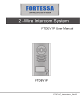
Handset
2 DOOR OPEN button
3. Increase value button
4. Decrease value button
Preset buttons:
ring tone volume
- select ring tone
brightness
saturation
LED indicators of a selected preset button
7 Switch to extra camera button
MONITOR button
Power LED
Screen
1
6
3
7
2
4
5
8
10
9
Screw 3.5 25- х Concrete Insert 6х30
x 3 x3
Fasteners
Operating Instruction
x1
- 440
Monitor
VIZIT M C
x1
Figure Appearance and controls layout1-

SAFETY INSTRUCTIONS
CAUTION 27V
FEATURES
!The Monitor does not contain voltage above .
Do not perform any connections or repair when the power is on.
Colour 3 5
Operation with two doorstations and extra camera (commutator BKM-440 required)
Operation with one doorstation, door bell button and extra camera (commutator BKM-440 not required)
Calls from doorstation and door bell button
Duplex intercom
Remote door unlocking with the button
Door zone video monitoring
Activation of individual / storey doorstation by subscriber (duplex intercom and video monitoring)
5 ring tones, individual ring tone for each doorstation and door bell button.
3 ring volume levels
Individual image brightness and saturation for each doorstation and extra camera
LED indication of operating modes
v
v
v
v
v
v
v
v
v
v
v
v
. ” TFT LCD
Take care not to spill any liquids or chemically active substances on the product.
Unplug the power supply unit before cleaning the monitor. Clean by wiping with dry soft cloth. Do not use any liquid
cleaners, aerosol cleaners or abrasive agents.
Do not attempt to service the product by yourself. Please refer all services to qualified service personnel.
3
2
1
Connect the wires to the terminals of
your monitor as shown in Fig. 4-7.
Match the monitor’s fixing lugs with
the screws in the wall, and hook the
monitor on the screws.
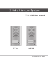
Figure Rear view2-
Figure Installation order3-
1
3
5
2
6
4
4
1
3
2
Connecting terminals
DC IN to connect power supply
unit SA03010029
Recess for cables
4
6
5
Inlets for cables
Fixing lugs
Socket for handset jack
2
Choose the position for monitor Recommended altitude is 150 cm from the floor to the monitor center..
3
Connect the handset
to the monitor.
1
3
2
85
57
85
1
INSTALLATION
Make 3 holes in the wall.
Refer to page 25 for Mounting Pattern.
Drive in concrete inserts and screws
supplied with your monitor.

The monitor terminals and their destination are given below
See Fig. 4 - 7 for the of the monitor and other doorphone units.
Acceptable cross-sections of wires to connect the monitor to the power supply unit, doorstation / control unit (Fig. 4 - 5)
are given in the doorstation / control unit operating instructions.
Acceptable cross-sections of wires to connect the monitor to the commutator BKM-440 (Fig. 6 - 7) are given in the
commutator BKM-440 operating instruction.
If the monitor operates together with the commutator BKM-440, a door bell button connection is not available
:
.
examples of wiring diagrams
Note.
Terminal
LN +
LN -
GND
VI1
+E
DATA DATA exchange between monitor and commutator BKM-440
Supply voltage for monitor
VIDEO IN from doorstation built-in camera
Ground
Intercom line between monitor and commutator /doorstation
Destination
Ec1
Ec2
GND
VI2 VIDEO IN from cameraextra
Ground
Supply voltage for cameraextra
Supply voltage for doorstation built-in camera
Figure Monitor with
doorstation and extra camera
4 - VIZIT-M440C multi-apartment
To next commutators
To other apartments 82-Ohm resistor should be
connected between the VO
and VG terminals of the last
commutator in the circuit
- 440
MONITOR
VIZIT M C
Extra Camera
12 V max, 0.3 А
To doorstation / control unit
Door bell
button
Note. Door bell button can be installed near your apartment door, and
connected to the GND and DATA terminals of the monitor
Commutator
BK-4MV
or BK-4V()
VO
Ec
GND
LN-
GND
LN+
VI1
+E
DATA
Ec1
Ec2
GND
VI2
VO
VG
VG
-18
+18
V1
FA
LN
VG
V2
FB
LN
VG
V3
FC
LN
VG
V4
FD
LN
VG
GND
LINE
SEL
Ek VI
18В, 0.5А
Power Supply SA03010029
GND +E
DC IN
EXAMPLES OF WIRING DIAGRAMS

Figure 5 Monitor with individual / storey
doorstation and extra camera
-VIZIT-M440C
-18
+18
+12
-12
POWER SUPPLY
BPD18/12-1-1
V
1A
50
ELECTROMECHANICAL
LOCK R 10 OHM)(
LINE
GND
+E
VO
Ec
LC
BVD 410CBL-
LN-
GND
LN+
VI1
+E
DATA
Ec1
Ec2
GND
VI2
MONITOR
VIZIT M C- 440
VO
Ec
GND Extra Camera
12 V max, 0.3 А
Door bell
button
INDIVIDUAL / STOREY
DOORSTATION
Colour
Figure Monitor as the main device with
doorstation, individual / storey doorstation and extra camera
6 - ( )VIZIT-M440C multi-apartment
HS+
COMMUTATOR
BKM-440
HS-
LN1-
GND
VI2
+E
L1N+
LN2-
VI1
LN2+
Ec1
Ec2
+E
GND
LN-
GND
LN+
+E
DATA
VO1
HS/MON
EQUIV
AB
C
VO2
GND
VO
Ec
GND
Extra Handset
INDIVIDUAL / STOREY
DOORSTATION
+
-
LN
GND
+E
Ec
LC
-BVD 406CB
VO
VG
To next commutators
To other apartments
VO
VG
VG
-18
+18
V1
FA
LN
VG
V2
FB
LN
VG
V3
FC
LN
VG
V4
FD
LN
VG
GND
LINE
SEL
Ek VI
82-Ohm resistor should be connected
between the VO and VG terminals
of the last commutator in the circuit
COMMUTATOR
BK-4MV
or BK-4V()
To
doorstation / control unit
multi-apartment
-18
+18
+12
-12
POWER SUPPLY
BPD18/12-1-1
Main Monitor
·
·
Individual / storey doorstation activation
Switching of video channels
Intercom priority over Extra Handset
·
Extra Camera
12 V max, 0.3 А
V
1A
50
ELECTROMECHANICAL
LOCK R 10 OHM)(
LN-
GND
LN+
VI1
+E
DATA
Ec1
Ec2
GND
VI2
- 440
MONITOR
VIZIT M C

Figure Monitor as extra device
with two individual / storey doorstations
7 - VIZIT-M440C ()
BVD-401СВ
LN
LС
+E
Ec
VO
GND
LN
GND
+E
Ec
LC
BVD 406CB-
VO
VG
- 460
MONITOR
TERMINAL
VIZIT MT CM
-18
+18
+12
-12
POWER SUPPLY
BPD18/12-1-1
HS+
COMMUTATOR
BKM-440
HS-
LN1-
GND
VI2
+E
L1N+
LN2-
VI1
LN2+
Ec1
Ec2
+E
GND
LN-
GND
LN+
+E
DATA
VO1
HS/MON
EQUIV
AB
C
VO2
GND
-18
+18
+12
-12
POWER SUPPLY
BPD18/12-1-1
Extra Monitor
Main Monitor
INDIVIDUAL / STOREY
DOORSTATION
INDIVIDUAL / STOREY
DOORSTATION
V
1A
50
ELECTROMECHANICAL
LOCK R 10 OHM)(
ELECTROMECHANICAL
LOCK R 10 OHM)(
V
1A
50
LN-
GND
LN+
VI1
+E
DATA
Ec1
Ec2
GND
VI2
- 440
MONITOR
VIZIT M C
·
·
Individual / storey doorstation
activation - N/A
Switching of video channels - N/A
LN-
GND
LN+
+E
DATA
VI
AWAY REC
MENU
·
·
Individual / storey doorstation
activation
Switching of video channels
Intercom priority over Extra
Monitor
·

SETUP
Turn on the power supply unit or commutator BKM-440.
Select a ring tone, set its volume, adjust brightness and saturation of colour image from doorstation
camera
Setting the ring tone volume (3 levels).
Selecting a new ring tone (one of five).
Adjusting image brightness
Adjusting colour image saturation
Quitting Setup Mode
individual
ring tone for calls from the door bell button, image brightness and saturation for the extra outdoor camera
ring tone volume same for both
extra
two doorstations main
individual ring tone, image brightness and saturation doorstations ring tone volume
same for both
Note
two doorstations extra individual
not available, same for both
Before turning the power on, make sure that there is no misconnection or risk of short circuit.
The monitor Power LED (see Fig.1) illuminates with green light. If the Power LED is dim, the monitor is in the sleep
mode (calls are ignored, and all buttons except for are disabled).
To switch the monitor on, press the button.
Press . Image from the doorstation camera appears on the screen. Press one of the preset buttons:
to set the ring tone volume;
to select new ring tone;
to adjust image brightness;
to adjust image saturation.
When you press the button, its LED indicator illuminates to show which setting is now active.
Press . LED indicator illuminates. Press to decrease or to increase volume. Every time you press either or
, the test sound rings to present the volume level, and the LED is blinking. When the lowest or the highest level is
reached, LED blinking stops.
Press . LED indicator illuminates. Press or to select a new ring tone. Every time you press either or , the
selected ring tone sounds.
Press . LED indicator illuminates. Press or . The LED is blinking. When the lowest or the highest degree of
brightness is reached, the LED blinking stops.
Press . LED indicator illuminates. Press or . The LED is blinking. When the lowest or the highest degree of
saturation is reached, the LED blinking stops.
To quit the setup mode immediately, pick up the handset and hang it up again. The screen shuts off.
The monitor quits the setup mode automatically in 15 seconds of idle, if you do not press , , , , or buttons
for 15 seconds.
If an extra camera and ordinary door bell button are connected to your monitor (see Fig. 4, 5), you can set an
and .
Note, that the remains the the doorstation and door bell button.
Press , then . Image from the camera appears on the screen.
Select a ring tone, set image brightness and saturation, as described above.
If are connected to your monitor via BKM-440, and used as the device (see Fig. 6), you can set
an for calls from both . The
remains the doorstations.
Press the button, image from the first (i.e. main entrance) doorstation appears in the monitor. Perform the settings as
described above.
Press the button once more, image from the second (individual/storey) doorstation appears on the screen. Perform
the settings as described above.
If your monitor is connected to via BKM-440, and used as an device (see Fig. 7),
settings for doorstations are they remain the doorstations.
To adjust current settings of the monitor as extra device, make a call from one of the connected doorstations. Image
arrears on the screen. Select a ring tone, set its volume, set image brightness and saturation, as described above.
§
§
§
§
§
1.
2.
.

FUNCTIONAL CHECK AND OPERATION ORDER
Note.
Special notes on operation with BKM-440
main extra
main intercom priority extra main monitor’s
extra extra
main
When a call is made from the doorstation, the monitor rings. Image from the doorstation camera appears on the screen.
Pick up the handset and check duplex intercom. During intercom, press to view image from the extra camera (see Fig. 4,
5, 6), if needed. Press again to switch back to the image from the doorstation camera.
To release the door lock, press and hold until the beep. The door is unlocked now. After you release the button,
intercom is still available. Hang up the handset. The screen shuts off, the monitor goes to the Stand-By mode.
You can unlock the door without picking up the handset. When called, just press and hold until the beep. The
door is unlocked now .After you release , the monitor goes to the Stand-By mode.
To activate the individual / storey doorstation (i.e. start intercom and video monitoring on your initiative, see Fig. 5), pick
up the handset. Image appears on the screen, intercom is available. You can press to view image from the extra
camera, if needed. Press again to switch back to the image from the doorstation camera.
At pressing the door bell button, the monitor rings, image from the extra camera appears on the screen (see Fig. 4, 5).
To engage the sleep mode, press and hold until the Power LED turns off.
The monitor can be connected to the BKM-440 either as the (see Fig. 6) or the monitor (see Fig. 7). The
monitor has an over any device, i.e. when you pick up the handset, the
monitor (or extra apartment handset) is disengaged. The monitor cannot activate the individual / storey
doorstation.
To view the door zone in front of main entrance doorstation (see Fig. 6), press on the monitor, or pick up its
handset. To switch to viewing the door zone in front of individual / storey doorstation, press again. To start intercom
with the individual / storey doorstation, pick up the handset.
Ambient temperature range + to +
Relative humidity of air up to at +
5°C 40°C
93% 25°C
SPECIFICATIONS
3.5” (89mm)
Ohm
V p-p
VDC
W
14 mm
0.6 kg
OPERATING CONDITIONS
Screen
Colour system
Video IN
impedance
voltage
Operating voltage
Power consumption max.
Dimensions (W)x(H)x(D) x x
Weight
TFT LCD
PAL
470
1…1.8
15…27
3
0 183 48
:
-
-
1/7