Page is loading ...

Installation Instructions
PowerFlex 750-Series Option Modules
These instructions cover the installation of the option modules listed below.
For instructions on installing Network Communication option modules, refer to publication 750COM-IN002
.
Compatible Ports
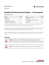
Option Module Installation Using 20-750-S1 with 20-750-DENC-1
20-750-APS
20-750-S
20-750-S1
20-750-2262C-2R
20-750-2263C-1R2T
20-750-2262D-2R
20-750-1132C-2R
20-750-1133C-1R2T
20-750-1132D-2R
20-750-ENC-1 20-750-DENC-1
20-750-UFB-1
20-750-ATEX
Option Module
Cat. No. 20-750-
PowerFlex 753 Drives PowerFlex 755 Drives
Frame 1 Ports Frame 2…7 Ports Frame 1 Ports Frame 2…10 Ports
APS See Page 2 See Page 2 See Page 2 Yes No No No No
2262C-2R, 2263C-1R2T, 2262D-2R No Ye s Yes Yes Yes Ye s No Ye s Yes Ye s Ye s Yes Ye s Yes
1132C-2R, 1133C-1R2T, 1132D-2R No Ye s Yes Yes Yes Ye s No Ye s Yes Ye s Ye s Yes Ye s Yes
1132C-2R, 1133C-1R2T, 1132D-2R
with 20-750-ATEX installed
(1)
No Ye s Yes No Yes Ye s No Ye s Yes No No No Ye s Ye s
ENC-1 No Ye s Yes Yes Yes Ye s No Ye s Yes Ye s Ye s Yes Ye s Yes
UFB-1 Not Supported No Ye s Yes No No Yes Ye s Yes
S Yes Ye s Yes Ye s Yes Yes Ye s Yes Yes Ye s Yes Ye s Yes Yes
S1
(2)
Yes Ye s Yes Ye s Yes Yes Ye s Yes Yes No No Ye s Yes Ye s
DENC-1
(2)
No Ye s Yes Yes Yes Ye s No Ye s Yes Ye s Ye s Yes Ye s Yes
(1) For detailed instructions on installation of 11-Series I/O with the ATEX option module, refer to the PowerFlex 750-Series ATEX User Manual, publication 750-UM003.
(2) See Using 20-750-S1 with 20-750-DENC-1.
0.45 N•m (4.0 lb•in)
20-750-S1
20-750-DENC-1
IMPORTANT: When a Safe Speed Monitor option
(20-750-S1) is used with a Dual Incremental Encoder
option (20-750-DENC-1) both modules must be
installed on the same backplane (ports 6, 5, 4).
IMPORTANT: Only one safety option module can be
installed at a time. Multiple safety options or duplicate
safety option installations are not supported.

www.rockwellautomation.com
Amer
i
cas:
Rockwell
Automation, 1201 South
Second
Street,
Milwaukee,
WI 53204
-
2496
USA,
Tel:
(1)
414.382.2000, Fax: (1)
414.382.4444
Europe
/
Middle East
/
Africa:
Rockwell
Automati
on,
Pegasus
Park,
De Kleetlaan 12a,
1831 Diegem, Belgium,
Tel: (32) 2 663
0600, Fax: (32) 2 663
0640
Asia Pacific: Rockwell Automation, Level 14,
Core F,
Cyberport
3, 100
Cyberport Road,
Hong Kong,
Tel: (852) 2887 4788, Fax:
(852) 2508
1846
Power,
Control
and
Information Solutions
Headquarters
U.S. Allen-Bradley Drives Technical Support - Tel: (1) 262.512.8176, Fax: (1) 262.512.2222, E-mail: [email protected]a.rockwell.com,
Online: www.ab.com/support/abdrives
*PN-311992*
PN-311992
Publication 750-IN002F-MU-P – April 2015
Supersedes 750-IN002E-MU-P – July 2013 Copyright © 2015 Rockwell Automation, Inc. All rights reserved. Printed in USA.
Auxiliary Power Supply (20-750-APS) Installation
A connector cable is provided with Auxiliary Power Supply option module for use in PowerFlex 753 Drives and in
PowerFlex 755 Frame 1 drives. The cable is used to connect the module to the backplane when installed on the upper
control pod brackets.
IMPORTANT: Do not use the Auxiliary Power Supply option module with Frame 8 and larger drives. Refer to the
PowerFlex 750-Series AC Drives Installation Instructions, publication 750-IN001
for information on connecting an
external power supply to Frame 8 and larger drives.
Option Module Installation next to a Profibus Option Module
If a PowerFlex 20-750-PBUS Profibus option module resides in the adjacent port
to the right of the port in which the new module is being installed, the lower T15
Torx™ head mounting screw (see Detail A) of the new module may electrically
contact the metal Profibus cable connector attached to the Profibus option
module. This may cause faulty operation. To help prevent this, perform the steps
below. If a PowerFlex 20-750-PBUS Profibus option module is not in that port,
disregard these steps.
1. Remove the lower T15 Torx head mounting screw shown in Detail A,
from the new module being installed.
To remove the captive T15 Torx head screw, the module must be removed
to back the screw out of the mounting clip.
2. Replace the larger T15 Torx head screw with the smaller spare T8 Torx
head mounting screw that was shipped with the PowerFlex 20-750-PBUS
Profibus option module.
Detail A
Profibus Option
Module
/