Page is loading ...

Publication 20P-IN069A-EN-P
PowerFlex® DC Drive
Frame D Overvoltage Clipping Board Fuse Replacement
Installation Instructions
What This Kit Includes
• Fuses 14x51 mm, 10 A, 90V (3)
• Static strap
Tools That You Need
• Flathead screwdriver
ATTENTION: Only qualified personnel familiar with DC drives
and associated machinery should plan or implement the installation,
start-up and subsequent maintenance of the system. Failure to comply
may result in personal injury and/or equipment damage.
ATTENTION: To avoid an electric shock hazard, ensure that all
power to the drive has been removed before performing the following.
ATTENTION: This drive contains ESD (Electrostatic Discharge)
sensitive parts and assemblies. Static control precautions are required
when installing, testing, servicing or repairing this assembly.
Component damage may result if ESD control procedures are not
followed. If you are not familiar with static control procedures,
reference A-B publication 8000-4.5.2, “Guarding Against
Electrostatic Damage” or any other applicable ESD protection
handbook.

Publication 20P-IN069A-EN-P
2
What You Need to Do
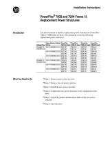
1. Remove and lock-out all incoming power to the drive.
2. Disconnect the DPI cable from the HIM (if present).
3. Insert a flathead screwdriver into the holes in the right side of the protective
covers on the drive and turn the latch 90° counter-clockwise.
4. Open the control panel to the left.
ATTENTION: Remove power before making or breaking cable
connections. When you remove or insert a cable connector with
power applied, an electrical arc may occur. An electrical arc can
cause personal injury or property damage by:
• sending an erroneous signal to your system’s field devices,
causing unintended machine motion
• causing an explosion in a hazardous environment
Electrical arcing causes excessive wear to contacts on both the
module and its mating connector. Worn contacts may create electrical
resistance.
L1 L2 L3
O
I
=
90°
Disconnect DPI cable
Overvoltage clipping
board mounted inside
drive on this side wall.
Resistors mounted
inside drive on back
wall of frame.


Publication 20P-IN069A-EN-P - May 2010
Copyright © 2010 Rockwell Automation. All rights reserved. Printed in USA.
www.rockwellautomation.com
A
mericas:
Rockwell
Automation,
1201
South
Second
Street,
Milwaukee,
WI
53204-2496
USA,
Tel:
(1) 414.382.2000
,
Fax:
(1)
414.382.4444
Europe/Middle East/Africa:
Rockwell
Automation
SA/NV,
Vorstlaan/Boulevard
du Souverain
36,
1170 Brussels,
Belgium,
Tel:
(32) 2 663
0600,
Fax:
(32) 2 663 0640
A
sia
Pacific:
Rockwell
Automation,
Level 14,
Core F,
Cyberport 3,
100 Cyberport Road,
Hong
Kong,
Tel:
(852) 2887 4788,
Fax:
(852) 2508 1846
Power, Control and Information Solutions
/