Page is loading ...

Mounting instruction 28 May 2015
011562 (replaces 0171-947)
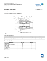
Shaft seal for screw compressor type SAB 202
162
160B
160C
134
135
166
165
160D
161
1 10
1 13
167
160E
160A
3-4 mm
T0177135_13
Spare parts sets contain
Designation Pos. no. Quantitity Part no.
Shaft seal complete for SAB 202 160 1 1332.176
Shaft seal HD complete for SAB 202 160 1 1332.208
Each set consists of:
Rotating part with carbon face 160A 1
Cast-iron seat 160B 1
Inner O-ring 160C 1
Outer O-ring 160D 1
Set screws 160E 1
O-ring for cover 166 1
Johnson Controls Denmark ApS
Christian X's Vej 201 ∙ 8270 Højbjerg ∙ Denmark
Phone +45 87 36 70 00 ∙ Fax +45 87 36 70 05 ∙ www.sabroe.com
CVR No 19 05 61 71
Page 1 of 3

The shaft seal must ensure complete tightness between the compressor shaft and the compressor housing, so
that the inside of the compressor is completely sealed off from the atmosphere.
The shaft seal has a built-in rotating part, which, apart from ensuring tightness, also assimilates axial displacement
and provides the necessary compressive force between the two slide faces mentioned below.
The shaft seal is a slide ring type, consisting of a stationary cast-iron seat, pos. 160B, which is positioned in the
shaft seal cover, pos. 165. Rotation is prevented by a retaining pin, pos. 161.
The end surface of the cast-iron seat is lapped in order to create tightness as a slide surface. The O-ring, pos.
160D, seals against the shaft seal cover, pos. 165.
The rotating part of the shaft seal, in which the carbon ring is mounted, is fastened at the rotor shaft by the 4 set
screws, pos. 160E, and sealed by means of the stationary O-ring, pos. 160C.
Note: Be very careful with the lapped slide surfaces on the cast-iron slide ring and the carbon slide ring as the
slightest scratch will impair their sealing effect.
Dismantling of shaft seal
Take the pressure off the compressor as described earlier, and dismantle the coupling.
Remove the screws, pos. 167, and pull the shaft seal cover out of the shaft.
In case the cover sticks, it can be pushed out by mounting two screws, pos. 167, in the two threaded holes of the
cover.
The oil throw-off ring, pos. 162, and the cast-iron seat, pos. 160B, will emerge with the cover.
After the 4 screws, pos. 160E, have been loosened a couple of turns, the rotating part of the carbon ring can now
be pulled out over the shaft. Normally, no auxiliary tools are needed.
Mounting of shaft seal
Due to the potential risk of releasing refrigerant and oil to the environment, if installation is not performed with the
necessary care, the procedure has to be followed closely.
• Clean the rotor shaft end thoroughly.
Special attention should be given to burrs from installation of former shaft seals. Slight grinding of the
shaft surface with emerald paper may be necessary to remove sharp edges.
• Apply a thin layer of clean lubrication oil as used for the compressor to the shaft surface and the O-rings.
Avoid touching the carbon face of the rotating part with the fingers.
DO NOT use any kind of grease for the installation.
• Carefully press the rotating part over the rotor shaft until it touches the balance piston, pos. 134.
DO NOT press against the carbon ring, but use the necessary force to the ring part inside the bellows
only. Be sure that the inner ring has full contact with the balancing piston.
• Tighten the 4 set screws, pos. 160E, in turn until reaching slight contact with the shaft surface.
Then carefully cross-span, with a slightly increasing torque, being aware that the rotating part must re-
main in center with the rotor shaft. Finally tighten to the correct torque.
Use 4 Nm for the normal shaft seal, part no. 1332.176
Use 7.5 Nm for the HD shaft seal, part no. 1332.208
An Allen key is included in the delivery.
Johnson Controls Denmark ApS
Christian X's Vej 201 ∙ 8270 Højbjerg ∙ Denmark
Phone +45 87 36 70 00 ∙ Fax +45 87 36 70 05 ∙ www.sabroe.com
CVR No 19 05 61 71
Page 2 of 3

After tightening carefully, press the outer ring - without touching the carbon face – to make sure that the
outer ring can axially move freely on the shaft.
• Install the O-ring, pos. 160D, into the groove of the cover, and press in the static seat, pos. 160B, until it
has contact with the bottom face. Avoid touching the sliding face with the fingers, but use a clean cloth or
similar when pressing.
Make sure that the retaining pin, pos. 161, catches the slot in the seat.
A few drops of clean oil may be applied to the sliding face.
• Guide the shaft seal cover carefully over the shaft until the shaft seal seat just touches the carbon face of
the rotating part. A gap of 3-4 mm between the shaft seal cover and the compressor housing will indicate
that the shaft seal is installed in its correct position. It may be necessary to do this check prior to the
mounting of the O-ring, pos. 166, in the cover, but remember to use the O-ring when the cover is installed
permanently. The screws, pos. 167, are tightened to the correct torque according to the general descrip-
tion in the instruction manual.
• Mount the oil throw-off ring, pos. 162. Mount the coupling as described in the instruction manual, and turn
the shaft by hand in order to check that it is running smoothly.
Jens Lund Christensen
Lead Engineer, Quality & Technical Design
Industrial Refrigeration Parts Centre
Building Efficiency
Direct no.: +45 87 36 77 42
Fax no.: +45 87 36 75 05
e-mail: [email protected]
Johnson Controls Denmark ApS
Christian X's Vej 201 ∙ 8270 Højbjerg ∙ Denmark
Phone +45 87 36 70 00 ∙ Fax +45 87 36 70 05 ∙ www.sabroe.com
CVR No 19 05 61 71
Page 3 of 3
/