Page is loading ...

Mounting instruction 27 February 2012
009573 (replaces 0171-930)
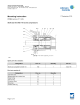
Balanced shaft seal type SB 100 on SMC 100, TSMC 100 and
HPC reciprocating compressor Rev. 3 (with o-ring pos. 10G)
•
•
•
•
••
•
•
•
•
The shaft seal SB 100 can be mounted on all types of SMC 100 compressors.
The following mounting instruction must be carefully followed when changing previous shaft seal by SB 100:
•Clean the crankshaft thoroughly where the shaft seal has to be mounted and check that its sealing faces
are smooth and free of scratches, blows and wear marks. Then oil in the crankshaft and the shaft seal
components thoroughly with the same type of oil as used in the compressor.
Johnson Controls Denmark ApS
Christian X's Vej 201 ∙ 8270 Højbjerg ∙ Denmark
Phone +45 87 36 70 00 ∙ Fax +45 87 36 70 05 ∙ www.sabroe.com
CVR No 19 05 61 71
Page 1 of 3

Mounting the shaft seal:
Unit with slide ring, Pos. 10E
1. Before fitting slide ring Pos. 10E, tighten screws Pos. 10J until there is approx. 2 mm spacing and parallelism
between the two flanges. Check also that locking ring Pos. 10H and O-ring Pos. 10D are in position, and
are mounted as shown in the drawing.
2. Position slide ring Pos. 10E on shaft and ensure tightening flange makes contact with shaft shoulder.
3. Crosswise, tighten screws Pos. 10J alternately with Allen key from tool kit. The torque is specified in the
instruction manual.
4. Check axial position of shaft seal by measuring distance from frame sealing face to slide face on Pos. 10E.
This must measure approx. 5.5 mm, as shown in the drawing.
Unit with shaft seal cover Pos. 8A
1. Mount the O-ring Pos. 10G and the ten spiral springs 10B in shaft seal cover Pos. 8A, then position carbon
slide ring Pos. 10F carefully. Rotate carbon slide ring so slot fits in over retention pin Pos. 8H.
2. Press carbon slide ring Pos. 10F against springs with your fingers and fit locking ring Pos. 8G. Observe
closely that the carbon slide ring is not overloaded by misbalanced pressure and that its slide face is not
damaged.
3. Give complete shaft seal cover an extra oiling on slide face of carbon slide ring and guide it in over shaft
together with gasket Pos. 8B.
4. Gently pressing shaft seal cover and carbon ring in against slide ring Pos. 10E without compressing springs
Pos. 10B, measure distance from gasket Pos. 8B to sealing face of shaft seal cover.
This distance must be about 3 mm. Make sure the hole for hose branch Pos. 8D faces down.
5. Mount screws Pos. 8C and tighten evenly, crosswise. This will avoid damaging the carbon slide ring. Tighten
screws Pos. 8C to prescribed torque according to table in instruction manual.
6. Mount oil throw ring pos. 8F, as shown in drawing.
7. After mounting coupling flange or V-belt disk, it must be possible to turn the crankshaft easily by hand.
Dismantling and stripping down shaft seal
1. Once the gas pressure in the compressor has been eliminated and the motor safeguarded against inad-
vertent start-up, dismantle coupling or V-belt disk.
Note: On units featuring coupling, there is no need to move the motor, as the coupling and the shaft seal
can be taken out between the two shaft ends.
2. Dismantle shaft seal cover Pos. 8A by alternately loosening bolts Pos. 8C so as to displace shaft seal cover
outwards without jiggling. This will avoid damage to internal parts of the shaft seal.
3. Once the spring force is equalized and the bolts removed, the shaft seal cover can be taken off the shaft
end by hand.
Take care so that no damage is done to the carbon slide ring Pos. 10F which comes out with it.
4. The carbon slide ring Pos. 10F can be taken out from the shaft seal cover by carefully pressing the carbon
ring in against the springs without damaging the lapped slide face, while the locking ring Pos. 8G is removed
with a small screwdriver.
The carbon ring Pos. 10F, the O-ring Pos. 10G and the spring Pos. 10B can then be taken out.
Johnson Controls Denmark ApS
Christian X's Vej 201 ∙ 8270 Højbjerg ∙ Denmark
Phone +45 87 36 70 00 ∙ Fax +45 87 36 70 05 ∙ www.sabroe.com
CVR No 19 05 61 71
Page 2 of 3

5. Dismantle slide ring Pos. 10E by turning four Allen screws Pos. 10J a max. of 2-3 turns; the entire unit can
then be taken out with the fingers or using two screwdrivers inserted into the external groove on the slide
ring Pos. 10E.
6. The O-ring Pos. 10D can now be removed.
Spare parts no 3184-225 contains the following parts:
8B Gasket for shaft seal cover
10E Slide ring (cast iron)
10F Slide ring (special carbon)
10D O-ring ID 75.69 x 3.53
10G O-ring ID 82.15 x 3.53
10J Four socket cap screw M5 x 16. One Allen key for socket cap screws.
Erhardt Nielsen
Manager, Reciprocating Compressors
Technical Support and Development
Direct no.: +45 87 36 77 20
Fax no.: +45 87 36 77 05
E-mail: [email protected]
Johnson Controls Denmark ApS
Christian X's Vej 201 ∙ 8270 Højbjerg ∙ Denmark
Phone +45 87 36 70 00 ∙ Fax +45 87 36 70 05 ∙ www.sabroe.com
CVR No 19 05 61 71
Page 3 of 3
/