Page is loading ...

CMO/TCMO 20-30 - HPO 24-26-28 (including ATEX)
Reciprocating compressor units
Engineering manual (including installation and service) EN


Engineering manual - CMO/TCMO 20-30 and HPO 24-26-28 (including ATEX)
007599 en 2022.10 3/253
Manual for CMO/TCMO 20-30 and HPO 24-26-28
Compressor type
CMO 24 CMO 26 CMO 28 TCMO 28
CMO 34 CMO 36 CMO 38 TCMO 38
HPO 24 HPO 26 HPO 28
Compressor no.
Refrigerant R717 R22 R134a
R404A R507 R744 Other _____
Control UniSAB III None Other
Compressor
cooling
Thermopump
Water-cooled top and side covers
Air-cooled top and side covers
Air-cooled top covers and water-cooled side covers
Air-cooled top and side covers + oil cooling (refrigerant-cooled)
Drive type Fixed speed Variable speed (VSD)
Ex-execution
(ATEX) T3 T4 Other ________
Additional suction filter
Oil return on parallel systems
Oil separator Sabroe OVUR Sabroe OHUR
Intermediate
cooling system
With internal intermediate cooling system
With external intermediate cooling system

Engineering manual - CMO/TCMO 20-30 and HPO 24-26-28 (including ATEX)
4/253 007599 en 2022.10
Safety valve:
Data for calculation of
downstream line accord-
ing to EN 13136
Vessel data
Type External surface
[m2]
Design pressure
[bar]
Condenser
Evaporator
Liquid separator
Oil separator
Oil cooler
Economiser
Desuperheater
Subcooler
Other
Pressure loss, if any, from safety valve to customer connection
(based on design pressure) [bar] _____________
Safety valve type:
Back-pressure dependent
Back-pressure independent

Engineering manual - CMO/TCMO 20-30 and HPO 24-26-28 (including ATEX)
007599 en 2022.10 5/253
Contents
1. Introduction......................................................................................... 14
1.1 Main users ................................................................................14
1.2 Models covered .........................................................................14
1.3 Amendments to the manual ........................................................ 15
1.4 Manufacturer's information ......................................................... 16
1.5 Safety precaution definitions used in this manual.......................... 17
1.6 Requirements for competent persons .......................................... 17
2. Signs and warnings............................................................................. 18
2.1 Main users ................................................................................18
2.2 Identification of equipment ..........................................................18
2.3 Unit/pipe system name plate.......................................................19
2.4 Compressor name plates............................................................ 21
2.5 Labelling of explosion-proof equipment........................................23
2.6 Vessel name plate...................................................................... 24
2.7 Signs .......................................................................................25
3. Safety precautions .............................................................................. 26
3.1 Areas of application.................................................................... 26
3.1.1 Application .........................................................................26
3.1.2 Application of combustion engines ....................................... 26
3.2 Safety precautions .....................................................................27
3.2.1 Emergency stop.................................................................. 27
3.2.2 General precautions............................................................ 27
3.2.3 Work area safety.................................................................28
3.2.4 During operation .................................................................28
3.2.5 Transmission safety ............................................................ 29
3.2.6 Cooling water system..........................................................29
3.2.7 Safety during maintenance and service ................................ 29
3.2.8 Electrical installations..........................................................30
3.2.9 Power supply...................................................................... 31
3.2.10 Lubricating oils ................................................................... 31
3.2.11 Refrigerants ....................................................................... 31
3.2.12 Purging a refrigeration plant................................................. 32
3.2.13 F-gas regulation (fluorinated greenhouse gases)................... 32
3.2.14 First aid for accidents with ammonia..................................... 34
3.2.15 First aid for accidents with HFC/HCFC .................................35
3.2.16 First aid for accidents with carbon dioxide (CO2).................... 36
3.2.17 Protecting the operator as well as the environment ................ 37
3.2.18 Noise data.......................................................................... 40

Engineering manual - CMO/TCMO 20-30 and HPO 24-26-28 (including ATEX)
6/253 007599 en 2022.10
3.2.19 Noise data for CMO, TCMO and HPO compressors .............. 40
4. Technical description .......................................................................... 43
4.1 Compressor data ....................................................................... 43
4.1.1 Description of CMO/TCMO and HPO compressors................ 43
4.1.2 Cylinder lining with suction valve .......................................... 45
4.1.3 Discharge valve .................................................................. 45
4.1.4 Connecting rod ................................................................... 45
4.1.5 Suction filter ....................................................................... 46
4.1.6 Extra suction filter (non-standard)......................................... 46
4.1.7 Relief valve ........................................................................46
4.1.8 Crankshaft .........................................................................47
4.1.9 Bearings for crankshaft .......................................................47
4.1.10 Oil pump ............................................................................47
4.1.11 Oil pressure regulating valve................................................ 47
4.1.12 Oil filter .............................................................................. 47
4.1.13 Shaft seal........................................................................... 47
4.1.14 Heating element .................................................................48
4.1.15 Oil charging and drain valve................................................. 48
4.1.16 Evacuating valve ................................................................ 49
4.1.17 Stop valves ........................................................................49
4.1.18 Cooling of compressor and oil.............................................. 49
4.1.19 Oil consumption.................................................................. 49
4.1.20 Oil separation and oil return on CMO/TCMO and
HPO .................................................................................. 50
4.1.21 Oil return in connection with parallel operation ......................54
4.1.22 System A ........................................................................... 54
4.1.23 System C ........................................................................... 57
4.2 Capacity regulation of compressor .............................................. 59
4.2.1 Standard capacity regulation ...............................................59
4.2.2 Capacity regulation and unloaded start.................................60
4.2.3 Function............................................................................. 61
4.2.4 Extended unloading ............................................................ 62
4.2.5 VSD unloading ................................................................... 63
4.2.6 TCMO compressor ............................................................. 64
4.2.7 TCMO with capacity regulation ............................................64
4.2.8 Capacity regulation ............................................................. 65
4.2.9 TCMO without capacity regulation........................................65
4.3 Hot-gas-controlled capacity regulation, HPO only .........................65
4.3.1 Solenoid valve for hot-gas-controlled capacity
regulation........................................................................... 65
4.3.2 Hot gas capacity regulation in compressors using refriger-
ant R744 (CO2), HPO only...................................................67
4.3.3 Variable speed drive (VSD).................................................. 68

Engineering manual - CMO/TCMO 20-30 and HPO 24-26-28 (including ATEX)
007599 en 2022.10 7/253
4.3.4 Compressor unit .................................................................69
4.4 Instrumentation.......................................................................... 69
4.4.1 UniSAB III reading, safety and capacity regulating
system ............................................................................... 69
4.5 Cooling systems for compressor ................................................. 71
4.5.1 Refrigerant-cooled oil cooler for CMO and HPO
compressors ...................................................................... 71
4.5.2 Cooling of intermediate gas on TCMO .................................. 73
4.5.3 Intermediate cooling system with intermediate cooler type
VMA, R717.........................................................................73
4.5.4 Intermediate cooling system with liquid injection into the in-
termediate discharge gas, HFC/HCFC and R717 ..................75
4.5.5 Water-cooling of the reciprocating compressor......................79
4.6 Selecting lubricating oil for Sabroe recip. compressors..................84
4.6.1 Oil charge .......................................................................... 84
4.7 Compressor accessories ............................................................ 84
4.7.1 Thermopump cooling of R717 reciprocating
compressor ........................................................................84
5. Physical and connection data ............................................................. 86
5.1 Safety precautions .....................................................................86
5.2 Physical data ............................................................................. 86
5.3 Connections on CMO/HPO 24-26-28...........................................87
5.4 Connections on TCMO 28/38......................................................88
5.5 Electrical connections ................................................................ 89
5.6 Control of the unit....................................................................... 90
5.7 Pressure transmitters marked PT1, PT2 and PT3 .........................90
5.8 Temperature sensors .................................................................91
5.9 Heating element for oil heating.................................................... 92
5.10 Coils for solenoid valves ............................................................. 92
6. Technical data ..................................................................................... 93
6.1 Compressor data for reciprocating compressors CMO/TCMO/
HPO ......................................................................................... 93
6.2 Dimension sketches of compressor block ....................................94
6.3 Planning the machine room ........................................................ 95
6.4 Requirements for ambient temperatures and humidity ..................95
6.5 Operating limits.......................................................................... 97
6.5.1 Operating limits diagrams .................................................... 97
6.5.2 List of operating limits diagrams ......................................... 101
6.5.3 R717 Single-stage compressor CMO and SMC................... 101
6.5.4 R717 Two-stage compressor TCMO and TSMC.................. 102

Engineering manual - CMO/TCMO 20-30 and HPO 24-26-28 (including ATEX)
8/253 007599 en 2022.10
6.5.5 R717 Single-stage compressor HPO .................................. 103
6.5.6 R22 Single-stage compressor CMO and SMC..................... 104
6.5.7 R22 Two-stage compressor TCMO and TSMC.................... 105
6.5.8 R23 Single-stage compressor CMO and SMC..................... 106
6.5.9 R134a Single-stage compressor CMO ............................... 107
6.5.10 R134a Two-stage compressor TCMO and TSMC 100 S-
L...................................................................................... 108
6.5.11 R290 Single-stage compressor CMO and SMC................... 109
6.5.12 R290 Two-stage compressor TCMO and TSMC.................. 110
6.5.13 R404A Single-stage compressor CMO and SMC .................111
6.5.14 R404A Two-stage compressor TCMO and TSMC................ 112
6.5.15 R407C Single-stage compressor CMO ............................... 113
6.5.16 R407C Two-stage compressor TCMO and TSMC ............... 114
6.5.17 R507 Single-stage compressor CMO and SMC................... 115
6.5.18 R507 Two-stage compressor TCMO and TSMC.................. 116
6.5.19 R600 Single-stage compressor CMO ................................. 117
6.5.20 R600 Two-stage compressor TCMO and TSMC.................. 118
6.5.21 R600a Single-stage compressor CMO ............................... 119
6.5.22 R600a Two-stage compressor TCMO and TSMC ................ 120
6.5.23 R744 Single-stage compressor HPO .................................. 121
6.5.24 R1270 Single-stage compressor CMO and SMC................. 122
6.5.25 R1270 Two-stage compressor TCMO and TSMC ................ 123
6.5.26 LPG Single-stage compressor CMO and SMC .................... 124
6.5.27 LPG Two-stage compressor TCMO and TSMC ................... 125
6.6 Motor ...................................................................................... 126
6.6.1 Direction of rotation........................................................... 126
6.6.2 Choice of electric motor..................................................... 127
6.6.3 Starting torque of the compressor ...................................... 128
6.6.4 Moment of inertia .............................................................. 128
6.6.5 Handling of compressor and unit ........................................ 129
6.6.6 Compressor shaft ............................................................. 130
6.6.7 Coupling .......................................................................... 130
6.7 Noise and vibration .................................................................. 132
6.7.1 Vibration data for compressors - all compressor
types................................................................................ 132
6.7.2 Unbalanced forces and moments ....................................... 133
6.7.3 Noise data........................................................................ 136
6.7.4 Noise data for CMO, TCMO and HPO compressors ............ 137
6.8 Materials and pressure levels.................................................... 140
6.8.1 Specification of compressor materials ................................ 140
6.8.2 Test pressure levels for standard compressors and
components ..................................................................... 141
6.8.3 Tightness of Sabroe equipment.......................................... 142

Engineering manual - CMO/TCMO 20-30 and HPO 24-26-28 (including ATEX)
007599 en 2022.10 9/253
7. Installation instructions..................................................................... 143
7.1 Safety precautions ................................................................... 143
7.2 Installation data ....................................................................... 143
7.3 Installation and first start-up procedure ...................................... 143
7.4 Installation drawings................................................................. 143
7.5 Personnel requirements ........................................................... 143
7.6 Tools and accessories .............................................................. 144
7.7 Safety equipment..................................................................... 144
7.8 Preparing the mounting site ...................................................... 144
7.9 Laying the unit foundation......................................................... 145
7.10 Mounting directly on the foundation ........................................... 147
7.11 Damping using vibration dampers ............................................. 148
7.12 Mass damping between unit and building................................... 150
7.13 Marine installation.................................................................... 151
7.14 VSD equipment ....................................................................... 151
7.15 Installation instructions ............................................................. 152
7.16 Alignment................................................................................ 152
7.16.1 Alignment of unit against foundation ................................... 152
7.16.2 Mounting directly on foundation ......................................... 152
7.16.3 Alignment of compressor on base frame ............................. 153
7.16.4 Alignment of motor on base frame...................................... 153
7.16.5 Fitting and alignment of coupling ........................................ 154
7.16.6 Preliminary installation of coupling ..................................... 155
7.16.7 Inspection of coupling ....................................................... 157
7.16.8 Storage of rubber elements ............................................... 158
7.16.9 Alignment of coupling........................................................ 159
7.16.10 Achieving correct centre height .......................................... 159
7.16.11 Achieving parallel shafts in vertical plane ............................ 160
7.16.12 Final installation of coupling............................................... 160
7.17 Piping connections................................................................... 161
7.18 Connecting electricity supply..................................................... 162
7.19 Pressure testing....................................................................... 164
7.19.1 Final installation check ...................................................... 166
8. Components...................................................................................... 167
8.1 CMO/TCMO/HPO components ................................................. 167
8.1.1 Motors ............................................................................. 168
8.1.2 Transmission systems....................................................... 168
8.1.3 Direct drive....................................................................... 168
8.1.4 Oil separators................................................................... 168
8.1.5 Oil coolers........................................................................ 168

Engineering manual - CMO/TCMO 20-30 and HPO 24-26-28 (including ATEX)
10/253 007599 en 2022.10
8.2 Control and monitoring system.................................................. 169
8.2.1 UniSAB III ........................................................................ 169
9. Settings............................................................................................. 170
10. Operating instructions ...................................................................... 172
11. Maintenance instructions .................................................................. 173
11.1 Maintenance............................................................................ 173
11.1.1 Safety precautions ............................................................ 173
11.1.2 Maintenance of compressor unit ........................................ 173
11.1.3 Stopping routine ............................................................... 175
11.1.4 Service intervals ............................................................... 176
11.1.5 Service interval diagrams .................................................. 176
11.1.6 Annual service.................................................................. 179
11.1.7 Regular service schedule - refrigeration plant...................... 180
11.1.8 Regular service schedule .................................................. 181
11.1.9 Visual inspection............................................................... 182
11.1.10 Measures to be taken........................................................ 182
11.1.11 General rules for use of lubricating oil in refrigeration
compressors .................................................................... 184
11.1.12 Assessing the oil............................................................... 184
11.1.13 Analytical evaluation ......................................................... 184
11.1.14 Charging the compressor with lubricating oil ....................... 185
11.1.15 Oil charge - Oil level.......................................................... 186
11.1.16 Oil charge ........................................................................ 186
11.1.17 Compressor prelubrication................................................. 186
11.1.18 Oil charging and drain valve............................................... 188
11.1.19 Hand-operated oil pump .................................................... 188
11.1.20 Shaft seal......................................................................... 189
11.1.21 Motor lubrication ............................................................... 189
12. Faultfinding instructions ................................................................... 190
12.1 How to carry out faultfinding...................................................... 190
12.2 Remedying malfunctions .......................................................... 193
13. Service instructions .......................................................................... 200
13.1 Introduction ............................................................................. 200
13.2 General preparations before service.......................................... 200
13.3 Servicing the compressor and refrigeration plant ........................ 201
13.3.1 Pressure drop test ............................................................ 201
13.3.2 Removing refrigerant from the compressor ......................... 202
13.3.3 Inspection of shaft seal...................................................... 203
13.3.4 Checking the refrigeration plant ......................................... 204
13.3.5 General guidelines............................................................ 204

Engineering manual - CMO/TCMO 20-30 and HPO 24-26-28 (including ATEX)
007599 en 2022.10 11/253
13.4 Maintenance of reciprocating compressor.................................. 206
13.4.1 Preparation for maintenance.............................................. 206
13.4.2 If the compressor is operational ......................................... 206
13.4.3 If the compressor is inoperative.......................................... 206
13.5 Dismantling and assembly ........................................................ 207
13.5.1 Water covers .................................................................... 207
13.5.2 Top covers ....................................................................... 207
13.5.3 Mounting of top cover........................................................ 207
13.5.4 Discharge valve ................................................................ 208
13.5.5 Discharge valve types ....................................................... 209
13.5.6 Suction valve types ........................................................... 209
13.5.7 Service life of discharge and suction valves ........................ 209
13.5.8 Cylinder lining with suction valve ........................................ 210
13.5.9 Extracting cylinder lining.................................................... 210
13.5.10 Dismantling suction valve .................................................. 210
13.5.11 Mounting suction valve...................................................... 211
13.5.12 Inserting cylinder lining...................................................... 211
13.5.13 Connecting rod ................................................................. 211
13.5.14 How to remove piston and connection rod........................... 212
13.5.15 Fitting connecting rod........................................................ 212
13.5.16 Piston .............................................................................. 213
13.5.17 Procedure for removing piston and connection rod .............. 213
13.5.18 Dismantling of unloading cylinder ....................................... 213
13.5.19 Disassembly of unloading cylinder ..................................... 214
13.5.20 Assembly of unloading cylinder.......................................... 214
13.5.21 Mounting of unloading cylinder in the compressor ............... 214
13.5.22 Shaft seal......................................................................... 215
13.5.23 Assembling and mounting shaft seal .................................. 217
13.5.24 Crankshaft ....................................................................... 218
13.5.25 Dismantling crankshaft...................................................... 219
13.5.26 Inspection ........................................................................ 219
13.5.27 Refitting crankshaft ........................................................... 219
13.5.28 Main bearings................................................................... 220
13.6 Lubricating system ................................................................... 220
13.6.1 Compressor lubricating system .......................................... 220
13.6.2 Oil pump .......................................................................... 221
13.6.3 Dismantling of oil pump ..................................................... 222
13.6.4 Mounting of oil pump......................................................... 222
13.6.5 Oil pressure regulating valve.............................................. 222
13.6.6 Oil filter ............................................................................ 224
13.6.7 Changing oil filter cartridge ................................................ 224

Engineering manual - CMO/TCMO 20-30 and HPO 24-26-28 (including ATEX)
12/253 007599 en 2022.10
13.7 Relief valve ............................................................................. 225
13.7.1 Description of relief valve................................................... 225
13.8 Hot-gas-controlled capacity regulation....................................... 226
13.8.1 Dismantling and assembly of solenoid valves...................... 227
13.9 Coupling ................................................................................. 227
13.10 Refrigeration plant ................................................................... 227
13.10.1 Refrigeration plant maintenance ........................................ 227
13.10.2 Pumping down refrigeration plant ....................................... 227
13.11 Dismantling plant ..................................................................... 228
13.12 Tightness testing and pump down of refrigeration plant ............... 228
13.13 Spare parts ............................................................................. 228
13.13.1 How to order spare parts ................................................... 228
14. Transport instructions....................................................................... 230
14.1 Transport data ......................................................................... 230
14.2 Personnel requirements ........................................................... 230
14.3 Loading instructions ................................................................. 230
14.4 Transport instructions............................................................... 231
14.5 Unloading instructions .............................................................. 232
14.6 Storage ................................................................................... 232
15. Commissioning instructions ............................................................. 233
15.1 Safety precautions ................................................................... 233
15.2 Preparations for commissioning ................................................ 233
15.3 Preparing the installation site .................................................... 234
15.4 Commissioning instructions ...................................................... 234
15.5 Checklist for commissioning...................................................... 236
16. Spare parts list .................................................................................. 238
16.1 Please see separate Spare parts manual................................... 238
17. Spare parts drawings ........................................................................ 239
17.1 Please see separate Spare parts manual................................... 239
18. Final disposal.................................................................................... 240
18.1 Safety precautions ................................................................... 240
18.2 Waste disposal ........................................................................ 240
19. Appendices ....................................................................................... 241
19.1 Sundry clearances and check dimensions ................................. 241
19.2 Torque for screws and bolts ...................................................... 242
19.3 Connecting rod ........................................................................ 242

Engineering manual - CMO/TCMO 20-30 and HPO 24-26-28 (including ATEX)
007599 en 2022.10 13/253
19.4 General torque ........................................................................ 243
19.5 Coupling data .......................................................................... 245
19.6 Capacity diagrams for CMO, TCMO and HPO
compressors............................................................................ 246
Index ................................................................................................. 250

Engineering manual - CMO/TCMO 20-30 and HPO 24-26-28 (including ATEX)
14/253 007599 en 2022.10
Introduction
1. Introduction
The Sabroe reciprocating compressor and unit can be configured with various types of equip-
ment depending on its function and requirements. Some of the equipment may be described in
this manual even though it is not featured on your particular unit.
This all-in-one manual provides all compressor information needed for sales, installation, main-
tenance and service. Operating instructions and spare parts data are not included, but can be
found in the operating and spare parts manuals respectively.
The manual includes:
• Description of all component parts
• Description of all important technical functions to ensure a thorough understanding of
the product functionality
• Refrigerant safety
• Connecting data
• Installation, maintenance, service instructions
• and much more.
1.1 Main users
This manual is primarily intended for sales, service and contracting purposes.
All compressor intervention within the warranty period must be performed by competent per-
sonnel only. If not, the warranty no longer applies.
1.2 Models covered
• CMO 20-30
• TCMO 20-30
• HPO 24 -26 -28

Engineering manual - CMO/TCMO 20-30 and HPO 24-26-28 (including ATEX)
007599 en 2022.10 15/253
Introduction
1.3 Amendments to the manual
2022.10 Version 7
• The compressor, vessel and unit pipe system name plates have been updated.
• New section 6.8.3: Tightness of Sabroe equipment.
• New section: 13.3.3 Inspection of shaft seal.
• Subsection 15.5 Checklist for commissioning has been updated, and the list can be
filled in electronically.
• Various minor changes/corrections.
2021.04 Version 6
• Oil charging instructions changed, see section 11.1.16 Oil charge and Table 46.
• Principle diagram showing two compressors in parallel operation, section 4.1.22 Sys-
tem A, has been updated.
• Various minor changes/corrections.
2020.05 Version 5
• Section 6.4 Requirements for ambient temperatures and humidity has been updated
in accordance with the latest WHC (Water Heating and Cooling system) updates.
• Fig. 34 has been corrected for CMO/HPO 28–38.
• Various minor changes/corrections.
2019.09 Version 4
• The section ‘Water-cooling of the reciprocating compressor’ has been updated.
• Two tables showing ‘Unbalanced forces and moments’ have been added.
• Various minor changes/corrections.
2018.06 Version 3
• Noise data for 1800 rpm have been added.
• The ‘Storage’ section in the ‘Transport instructions’ chapter has been revised.
• Operating limits and more for R410A have been removed as the refrigerant has been
phased out.
• Cooling of side covers: the max. permissible cooling water pressure changed from 8 to
10 bar.
2018.03 Version 2
• Added information about ATEX, for example table with temperature classes.
• Name plates with EurAsian Conformity mark (EAC) have been added.
• A ‘Requirements for competent persons’ section has been added.
• The ‘F-gas regulation’ section has been updated.
• Declaration of conformity has been removed. It can be found in the operating
manuals.

Engineering manual - CMO/TCMO 20-30 and HPO 24-26-28 (including ATEX)
16/253 007599 en 2022.10
Introduction
1.4 Manufacturer's information
This manual is produced by:
Johnson Controls Denmark ApS
Christian X's Vej 201
8270 Højbjerg, Denmark
Phone +45 87 36 70 00
CVR No 19 05 61 71
www.sabroe.com
Copyright © Johnson Controls Denmark
This manual must not be copied without the written permission of Johnson Controls Denmark
and the contents must not be imparted to a third party nor be used for any unauthorised purpo-
ses. Contravention will be prosecuted.

Engineering manual - CMO/TCMO 20-30 and HPO 24-26-28 (including ATEX)
007599 en 2022.10 17/253
Introduction
1.5 Safety precaution definitions used in this manual
Danger!
Indicates an imminently hazardous situation which, if not avoided, will result in death or serious
injury.
Warning!
Indicates a potentially hazardous situation or practice which, if not avoided, will result in death
or serious injury.
Caution!
Indicates a potentially hazardous situation or practice which, if not avoided, will result in dam-
age to equipment and/or minor injury.
Note: Indicates an operating procedure, practice, or portion thereof, which is essential to
highlight.
1.6 Requirements for competent persons
• Personnel working on the unit must be competent in accordance with national safety
rules and regulations relating to flammable refrigerants or according to EN 13313.
• Maintenance work must be performed according to EN 378 or ISO 5149 supported by
evidence of appropriate training.
• Assign only competent personnel instructed in safety and all machine functions to oper-
ate or service the compressor/unit according to EN 13313.
• Operators and maintenance personnel must carefully read, understand and fully com-
ply with all alarms and instructions.

Engineering manual - CMO/TCMO 20-30 and HPO 24-26-28 (including ATEX)
18/253 007599 en 2022.10
Signs and warnings
2. Signs and warnings
This chapter describes:
• how to identify equipment from Johnson Controls Denmark
• all warning signs used on equipment delivered by Johnson Controls Denmark
• how information important to safety of personnel and equipment is presented in instruc-
tions belonging to equipment delivered by Johnson Controls Denmark
2.1 Main users
Information concerning Signs and warnings is intended for all users.
The following describes the importance of the individual signs attached to the Johnson Con-
trols Denmark products.
Before a compressor/unit is put into operation, it must be fitted with the warning signs belong-
ing to the type of compressor/unit in accordance with the rules and regulations in force.
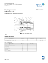
2.2 Identification of equipment
All Johnson Controls Denmark equipment can be identified by one or several name plates as il-
lustrated in the following:
Fig. 1: Identification of name plates
Unit pipe system name plate
Vessel name plateCompressor name plate

Engineering manual - CMO/TCMO 20-30 and HPO 24-26-28 (including ATEX)
007599 en 2022.10 19/253
Signs and warnings
2.3 Unit/pipe system name plate
Scope
Design code
Approval No
Refrigerant
Supply voltage
Test pressure
Allowable pressure
Category
Pressure system
Refrigerant charge
Max.
Allowable temp.
Min./Max.
Serial
Type
Year
Fluid
Group
Control
V/Hz
kg
bar
g
bar
g
°C
LP side
HP side
Johnson Controls Denmark ApS
Christian X's Vej 201
8270 Højbjerg, Denmark
www.sabroe.com
1000010126
MADE IN DENMARK
No
Fig. 2: Name plate for standard unit, with CE mark
Scope
Design code
Approval No
Refrigerant
Supply voltage
Test pressure
Allowable pressure
Category
Pressure system
Refrigerant charge
Max.
Allowable temp.
Min./Max.
Year
Fluid
Group
Control
V/Hz
kg
bar
g
bar
g
°C
LP side
HP side
1000010127
Main
Serial
Type
No
Johnson Controls Denmark ApS
Christian X's Vej 201
8270 Højbjerg, Denmark
www.sabroe.com
MADE IN DENMARK
Fig. 3: Name plate for ATEX unit
Scope
Design code
Approval No
Refrigerant
Supply voltage
Test pressure
Allowable pressure
Category
Pressure system
Refrigerant charge
Max.
Allowable temp.
Min./Max.
Year
Fluid
Group
Control
V/Hz
kg
bar
g
bar
g
°C
LP side
HP side
1000010128
Main
MADE IN DENMARK
Serial
Type
No
Johnson Controls Denmark ApS
Christian X's Vej 201
8270 Højbjerg, Denmark
www.sabroe.com
Fig. 4: Name plate for standard unit, without CE mark
Назначение
Код стандарта
№
сертификата
Хладагент
Группа
Напряжение питания
Управ
ление
В/Гц
Заправка хладагентом
Кг
Давление
бар
бар
Допустимое давление
Давление ислытания
макс
Категория
°
С
Допустимая темп
мин/макс
1000010129
Жидкость
Сеть
Сторона НД
Сторона ВД
ммгг
Тип
Johnson Controls Denmark ApS
Christian X´s Vej 201
8270 Højbjerg, Denmark
www.sabroe.com
СДЕЛАНО В ДАНИИ
Серийный
№
Fig. 5: Name plate for unit with EurAsian Conformity mark
(EAC)

Engineering manual - CMO/TCMO 20-30 and HPO 24-26-28 (including ATEX)
20/253 007599 en 2022.10
Signs and warnings
The unit name plate is positioned on the frame and contains this information:
Serial No. Unique identification number.
Year Year of manufacturing.
Type Manufacturer's type designation.
Scope
For EC PED/EAC approval: ‘Unit & Piping’ means that the CE/
EAC mark applies to the complete unit including the piping sys-
tem.
’Piping’ means that the CE/EAC mark applies to the piping sys-
tem only, and it is the sole responsibility of the owner to ensure
and declare that the complete unit is in conformity with the provi-
sions of all relevant rules.
Design code Design code used for the unit and piping system.
Approval no. If the unit/manufacture has been approved by a 3rd party/noti-
fied body.
Refrigerant - Fluid Refrigerant of the unit.
Refrigerant designation according to ISO 817.
Refrigerant - Group For EC PED approval:
Fluid group 1 or 2 according to the PED directive.
Supply voltage - Control Supply voltage and frequency of the control system.
Refrigerant charge
Weight of the refrigerant charge on the unit.
This is only stated if the unit includes an evaporator and/or a
condenser.
Pressure system
The low-pressure side of the unit piping system is referred to as
the LP side.
The high-pressure side of the unit piping system is referred to as
the HP side.
Category
For EC PED approval:
The maximum category of the piping system (CAT 1, 2 or 3) or
of the assembly unit and piping (CAT 3 or 4).
Allowable pressure, max.
The max. pressure (pressure relative to atmospheric pressure)
that the unit/piping system has been designed for in terms of
pressure strength design.
The maximum practical operation pressure is lower than the
maximum allowable pressure depending on the operating condi-
tions and safety equipment settings.
Test pressure The test pressure that the unit/piping system has been strength
tested with.
Allowable temperature,
min./max.
The minimum and maximum temperatures that the unit/piping
system has been designed for at the indicated maximum allow-
able pressures.
CE xxxx
The CE mark appears on the name plate for EC PED approval
only. The four digits make up the registration no. of the notified
body/3rd party in charge.
Ex If the unit is designed in accordance with the EC ATEX directive,
there is an Ex mark on the name plate.
EAC
The EurAsian Conformity mark (EAC) indicates that the unit is in
compliance with all relevant technical regulations of the Eura-
sian Customs Union.
Note: Main supply voltage can be found on the motor and/or electrical panel name plate.
/