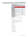
Allen-Bradley Rockwell Automation 1734-AENT User manual
- Category
- Networking
- Type
- User manual
This manual is also suitable for

POINT I/O EtherNet/IP Adapter Module
Catalog Number 1734-AENT
User Manual

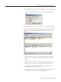
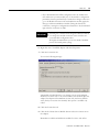
Important User Information
Solid state equipment has operational characteristics differing from those of electromechanical equipment. Safety Guidelines for the Application,
Installation and Maintenance of Solid State Controls (publication SGI-1.1
available from your local Rockwell Automation sales office or online at
http://literature.rockwellautomation.com
) describes some important differences between solid state equipment and hard-wired electromechanical
devices. Because of this difference, and also because of the wide variety of uses for solid state equipment, all persons responsible for applying this
equipment must satisfy themselves that each intended application of this equipment is acceptable.
In no event will Rockwell Automation, Inc. be responsible or liable for indirect or consequential damages resulting from the use or application of this
equipment.
The examples and diagrams in this manual are included solely for illustrative purposes. Because of the many variables and requirements associated
with any particular installation, Rockwell Automation, Inc. cannot assume responsibility or liability for actual use based on the examples and
diagrams.
No patent liability is assumed by Rockwell Automation, Inc. with respect to use of information, circuits, equipment, or software described in this
manual.
Reproduction of the contents of this manual, in whole or in part, without written permission of Rockwell Automation, Inc., is prohibited.
Throughout this manual, when necessary, we use notes to make you aware of safety considerations.
Allen-Bradley, Rockwell Automation, POINT I/O, RSLinx, RSLogix 5000 and TechConnect are trademarks of Rockwell Automation, Inc.
Trademarks not belonging to Rockwell Automation are property of their respective companies.
WARNING
Identifies information about practices or circumstances that can cause an explosion in a hazardous environment, which may
lead to personal injury or death, property damage, or economic loss.
IMPORTANT
Identifies information that is critical for successful application and understanding of the product.
ATTENTION
Identifies information about practices or circumstances that can lead to: personal injury or death, property damage, or
economic loss. Attentions help you identify a hazard, avoid a hazard, and recognize the consequence.
SHOCK HAZARD
Labels may be on or inside the equipment, such as a drive or motor, to alert people that dangerous voltage may be present.
BURN HAZARD
Labels may be on or inside the equipment, such as a drive or motor, to alert people that surfaces may reach dangerous
temperatures.

iii Publication 1734-UM011D-EN-P - January 2011
Preface
What This Preface Contains
This preface describes how to use this manual. See the table for a list of where
to find specific information within this chapter.
Who Should Use This
Manual
This manual is intended for control engineers and technicians who are
installing, configuring, and maintaining an EtherNet/IP control system that
communicates with POINT I/O modules through a 1734-AENT adapter. We
assume you have a good understanding of Ethernet networks and the TCP/IP
protocol.
Common Techniques Used
in This Manual
We use the following conventions throughout this manual:
• Numbered lists provide sequential steps.
• Bulleted lists provide information, not procedural steps.
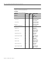
Topic Page
Who Should Use This Manual iii
Common Techniques Used in This Manual iii
How to Use This Manual iv
About the Example Applications iv
System Components v
Where to Find More Information vi
Terminology vii
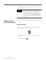
ATTENTION
You must use series C POINT I/O modules with the 1734-AENT
adapter. Series A or B POINT I/O modules will not work with
this adapter.
TIP
This symbol identifies helpful tips.
The screen captures shown in this manual are pictures of
the software’s actual screens.

Publication 1734-UM011D-EN-P - May 2011
iv Preface
How to Use This Manual
This manual contains an overview of the 1734-AENT adapter. It describes
how to install and configure the adapter and provides examples showing how
to use the adapter to communicate with POINT I/O modules over an
EtherNet/IP network.
About the Example Applications
This manual presents two example applications that demonstrate the
procedures for configuring and communicating with POINT I/O modules
using the 1734-AENT adapter. We intend the example applications as building
blocks to help you get your own system up and running. We recommend that
you set up and run the example applications and use them as guides.
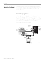
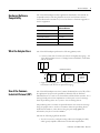
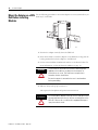
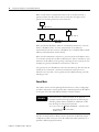
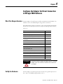
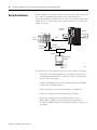
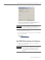
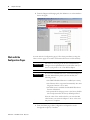
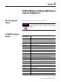
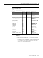
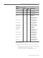
Here is the type of system you’ll be setting up.
Local
chassis
POINT I/O
Logix5555
controller (slot 1)
1756-ENBT
10.88.70.4 (slot 3)
Data
Switch
10.88.70.26
Programming
terminal
Slot 0 1 2 3
1734-AENT
10.88.70.2
Slot 0 1 2 3 4
31393-M

Publication 1734-UM011D-EN-P - May 2011
Preface v
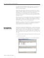
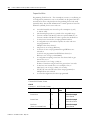
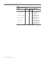
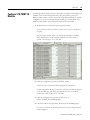
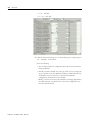
System Components
We used the following components for the example applications. You need the
same or similar components to set up your own control system using
POINT I/O modules on an EtherNet/IP network.
Quantity Product Name Catalog Number
Hardware
1 POINT I/O EtherNet/IP adapter 1734-AENT
1 POINT I/O 24V DC sink output
module
1734-OV4E/C
1 POINT I/O relay output module 1734-OW2/C
1 DIN rail 199-DR1 or equivalent
1 ControlLogix chassis 1756-A4 (or 1756-A7,
1756-A13,1756-A17)
1 ControlLogix power supply 1756-PA72 (or 1756-PB72)
1 Logix5555 controller 1756-L55
1 ControlLogix EtherNet/IP bridge
module
1756-ENBT
1 Personal computer that supports
RSLogix 5000 software
Any appropriate model running Windows
NT 4.0, Service Pack 6A or higher
1 Ethernet switch Refer to manufacturer’s specifications
1 24V DC power supply 1734-EP24DC
Associated media and connectors as needed
Software
1 RSLinx communications software,
version 2.31.00 or later
9355-WAB, 9355-WABOEM, 9355-WABC
1 RSLogix 5000 programming
software,
version 11.11 or later
9324-RLD300ENE

Publication 1734-UM011D-EN-P - May 2011
vi Preface
Where to Find More
Information
Refer to the following Rockwell publications as needed for additional help
when setting up and using your EtherNet/IP network.
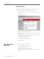
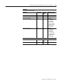
For Information About See This Publication Publication Number
Using EtherNet/IP for industrial control EtherNet/IP Performance and Application Guide ENET-AP001
Ethernet communication interface
modules
Ethernet Communication Interface Module Installation
Instructions
1756-IN053
Ethernet Communication Interface Module User Manual 1756-UM051
ControlLogix chassis ControlLogix Chassis Installation Instructions 1756-IN080 (series B)
ControlLogix power supplies ControlLogix Power Supplies Installation Instructions 1756-IN613 (PA72/PB72)
Logix5555 programmable controllers Logix5555 Controller User Manual 1756-UM523
SoftLogix5800 controller SoftLogix5800 User Manual 1789-UM002 (L10, L30, L60)
ControlLogix EtherNet/IP bridge module
with firmware revision 2.3 or later
ControlLogix EtherNet/IP Bridge Module Installation Instructions 1756-IN019
RSLogix 5000 programming software Getting Results with RSLogix 5000, version 3.2.1 or later 9399-RLD300GR
1734-AENT adapter POINT I/O EtherNet/IP Adapter Installation Instructions 1734-IN590
POINT I/O digital and analog modules
and PointBLOCK I/O modules
POINT I/O Digital and Analog Modules and PointBLOCK I/O
Modules User Manual
1734-UM001
POINT I/O interface modules POINT I/O RS-232 ASCII Module User Manual 1734-UM009
POINT I/O RS-232 ASCII Module Installation Instructions 1734-IN588
POINT I/O expansion power supply POINT I/O 24V DC Expansion Power Supply Installation
Instructions
1734-IN058
POINT I/O field potential distributor POINT I/O Field Potential Distributor Installation Instructions 1734-IN059
POINT I/O input modules POINT I/O 120V AC Input Module Installation Instructions 1734-IN010
POINT I/O Input Module Installation Instructions 1734-IN051
POINT I/O encoders/counter modules POINT I/O Encoders/Counter Module User Manual 1734-UM006
POINT I/O Encoders/Counter Module Installation Instructions 1734-IN005
POINT I/O 22V AC input module POINT I/O 220V AC Input Module Installation Instructions 1734-IN008
POINT I/O RTD and isolated
thermocouple input module
POINT I/O RTD and Isolated Thermocouple Input Module
Installation Instructions
1734-IN011
POINT I/O thermocouple and RTD input
module
Thermocouple and RTD Input Module User Manual 1734-UM004
POINT I/O IV2 and IV4 input module POINT I/O Input Module Installation Instructions 1734-IN052
POINT I/O 120/220V AC output module POINT I/O 120/220V AC Output Module Installation Instructions 1734-IN009
POINT I/O protected output module POINT I/O Protected Output Module Installation Instructions 1734-IN056
POINT I/O Protected Output Module Installation Instructions
(OB2EP)
1734-IN586
POINT I/O voltage output analog
module
POINT I/O 2 Voltage Output Analog Module Installation
Instructions
1734-IN002
POINT I/O protected sink output module POINT I/O Protected Sink Output Module Installation Instructions 1734-IN585

Publication 1734-UM011D-EN-P - May 2011
Preface vii
Terminology
Refer to the table for the meaning of common terms.
POINT I/O 2 relay output module POINT I/O 2 Relay Output Module Installation Instructions (OX2) 1734-IN587
POINT I/O 2 Relay Output Module Installation Instructions (OW2) 1734-IN055
POINT I/O synchronous serial interface
absolute encoder module
POINT I/O Synchronous Serial Interface Absolute Encoder
Module Installation Instructions
1734-UM007
POINT I/O cold junction compensation
wiring base assembly
POINT I/O Cold Junction Compensation Wiring Base Assembly
Installation Instructions
1734-IN583
POINT I/O wiring base assembly POINT I/O Wiring Base Assembly Installation Instructions 1734-IN013
Very high-speed counter module POINT I/O Very High-speed Counter Module Installation
Instructions
1734-IN003
Very High-speed Counter Module User Manual 1734-UM003
RSLinx RSLinx Enterprise Getting Results Guide LNXENT-GR001
For Information About See This Publication Publication Number
TIP
Many of these publications are available online from:
http://literature.rockwellautomation.com/
TIP
Rockwell Software products contain extensive tutorials and
help screens. We recommend that you use the tutorials and
help screens to learn about these products.
For more information about Rockwell Software products,
visit the Rockwell Software internet site:
http://www.software.rockwell.com
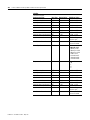
Term Definition
BootP BootP (Bootstrap Protocol) is a low-level protocol that provides
configurations to other nodes on a TCP/IP network. BootP
configuration files let you automatically assign IP addresses to an
Ethernet module. You can also obtain subnet masks and gateway
addresses from BootP.
Bridge A node between two similar communication subnets where protocol
translation is minimal.
CIP Control and information protocol, the EtherNet/IP application layer
uses the producer/consumer networking model. In this model one
producer broadcasts (multicasts) the data once to all the consumers.
All consumers see the data simultaneously and may choose whether
to consume (receive) the data or not. Delivery time is consistent, no
matter how many consumers there are.
Connection The communication mechanism from the controller to another
module in the control system, usually used to exchange I/O data.
Consumer A destination device in the CIP networking model. See CIP.

Publication 1734-UM011D-EN-P - May 2011
viii Preface
CSMA/CD Carrier sense multiple access/collision detection is the access
method used in Ethernet. When a device wants to gain access to the
network, it checks to see if the network is quiet (senses the carrier).
If it is not, it waits a random amount of time before retrying. If the
network is quiet and two devices access the line at exactly the same
time, their signals collide. When the collision is detected, they both
back off and each waits a random amount of time before retrying.
Determinism The ability to predict when information will be delivered. Important in
time-critical applications.
DHCP The dynamic host configuration protocol is an Internet protocol,
similar to BootP, for automating the configuration of computers that
use TCP/IP. DHCP can be used to automatically assign IP addresses,
to deliver IP stack configuration parameters, such as the subnet mask
and default router, and to provide other configuration information,
such as the addresses for printer, time, and news servers.
The 1734-AENT factory default is DHCP enabled. When you apply
power, the module sends a message containing its hardware address
to any DHCP server on the network. The server(s) replies by sending a
message with an appropriate IP address for the adapter. The adapter
responds by acknowledging to a server that it will use the offered IP
address.
DNS The domain name system is a hierarchical, distributed method of
organizing the name space of the Internet. The DNS administratively
groups hosts into a hierarchy of authority that allows addressing and
other information to be widely distributed and maintained. A big
advantage to the DNS is that using it eliminates dependence on a
centrally-maintained file that maps host names to addresses.
Ethernet A physical layer standard using carrier sense multiple access with
collision detection (CSMA/CD) methods.
EtherNet/IP Ethernet industrial protocol applies a common application layer (CIP)
over Ethernet by encapsulating messages in TCP/UDP/IP.
Ethernet network A local area network designed for the high-speed exchange of
information between computers and related devices.
Explicit messaging Non-time critical messaging used for device configuration and data
collection, such as downloading programs or peer-to-peer messaging
between two PLC units.
Full duplex A mode of communication that allows a device to send and receive
information at the same time, effectively doubling the bandwidth.
Fully qualified
domain name
A fully qualified domain name (FQDN) is a domain name that includes
all higher level domains relevant to the entity named. If you think of
the DNS as a tree-structure with each node having its own label, a
fully qualified domain name for a specific node would be its label
followed by the labels of all the other nodes between it and the root
of the tree. For example, for a host, a FQDN would include the string
that identifies the particular host, plus all domains of which the host
is a part, up to and including the top-level domain (the root domain is
always null). For example, PARIS.NISC.SRI.COM is a fully qualified
domain name for the host at 192.33.33.109.
Gateway A module or set of modules that allows communications between
nodes on dissimilar networks.
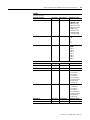
Term Definition

Publication 1734-UM011D-EN-P - May 2011
Preface ix
Hardware address
Each Ethernet device has a unique hardware address (sometimes
called a MAC address) that is 48 bits. The address appears as six
digits separated by colons (such as, xx:xx:xx:xx:xx:xx). Each digit has a
value between 0 and 255 (0x00 to 0xFF). This address is assigned in
the hardware and cannot be changed. The hardware address is
required to identify the device if you are using a BOOTP utility.
Host name The host name is the unique name for a computer within its domain.
It's always the first element of a full name, and, with its domain and
top-level domain suffix, creates the unique name of that computer on
the Internet. For example, let's say a trading website is
www.trading.com. The host name is www, which is not unique on
the web, but is unique within the trading domain.
The host name can also refer to the fully qualified domain name
(FQDN), or in this example, www.trading.com. Both naming methods
seem to be used interchangeably in various documents. For the
purposes of this document, the host name will refer to the FQDN, or
as in this example, www.trading.com.
Hub A central connecting device that joins devices together in a star
configuration. Hubs are generally not suitable for use in I/O control
systems, since they are time-critical applications that cannot tolerate
lost packets.
Implicit messaging Real-time messaging of I/O data.
IP Internet protocol that provides the routing mechanism for messages.
All messages contain not only the address of the destination station,
but the address of a destination network, which allows messages to
be sent to multiple networks within an organization or around the
world.
IP address A 32-bit identification number for each node on an Internet Protocol
network. These addresses are represented as four sets of 8-bit
numbers (numbers from 0 to 255), with decimals between them. Each
node on the network must have a unique IP address.
Latency The time between initiating a request for data and the beginning of
the actual data transfer.
Multicast In the CIP producer/consumer model, one producer multicasts
(broadcasts) the data once to all the consumers.
Producer The source of information in the CIP networking model. See CIP.
Rack-optimized A physical and logical collection of application modules.
Subnet mask An extension of the IP address that allows a site to use a single net
ID for multiple networks.
Switch A network device that cross connects devices or network segments.
A switch provides each sender/receiver the full network bandwidth
(2x in full duplex mode), reduces collisions, and increases
determinism.
TCP The transport control protocol is a more reliable but slower transport
protocol than UDP. It is used for explicit (not time critical) messaging
in EtherNet/IP.
Term Definition

Publication 1734-UM011D-EN-P - May 2011
x Preface
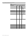
TCP/IP The transmission control protocol/internet protocol is a
transport-layer protocol (TCP) and a network-layer protocol (IP)
commonly used for communication within networks and across
internetworks.
Transaction An exchange of request and data and response and data
.
UDP The user datagram protocol (UDP) is a transport protocol that
provides a very simple but fast capability to send datagrams between
two devices. It is used for I/O (implicit) messaging in EtherNet/IP.
Term Definition

xi Publication 1734-UM011D-EN-P - May 2011
Table of Contents
Important User Information . . . . . . . . . . . . . . . . . . . . . . . . . . . . . . . . . . ii
Preface What This Preface Contains . . . . . . . . . . . . . . . . . . . . . . . . . . . . . . . . . .iii
Who Should Use This Manual. . . . . . . . . . . . . . . . . . . . . . . . . . . . . . . . .iii
Common Techniques Used in This Manual . . . . . . . . . . . . . . . . . . . . . .iii
How To Use This Manual . . . . . . . . . . . . . . . . . . . . . . . . . . . . . . . . . . . .iv
About the Example Applications . . . . . . . . . . . . . . . . . . . . . . . . . . .iv
System Components . . . . . . . . . . . . . . . . . . . . . . . . . . . . . . . . . . . . . v
Where to Find More Information . . . . . . . . . . . . . . . . . . . . . . . . . . . . . .vi
Terminology . . . . . . . . . . . . . . . . . . . . . . . . . . . . . . . . . . . . . . . . . . . . . . vii
Summary of Changes New and Revised Information . . . . . . . . . . . . . . . . . . . . . . . . . . . . xv
Change Bars . . . . . . . . . . . . . . . . . . . . . . . . . . . . . . . . . . . . . . . . . . . xv
Chapter 1
About the Adapter
What This Chapter Contains . . . . . . . . . . . . . . . . . . . . . . . . . . . . . . . . . . 1
Important Adapter Considerations . . . . . . . . . . . . . . . . . . . . . . . . . . . . . 1
Set the Chassis Size . . . . . . . . . . . . . . . . . . . . . . . . . . . . . . . . . . . . . . 1
Adapter Replacement . . . . . . . . . . . . . . . . . . . . . . . . . . . . . . . . . . . . 2
Empty Slots and RIUP Situations. . . . . . . . . . . . . . . . . . . . . . . . . . . 2
Cycle Power To a System For the First Time . . . . . . . . . . . . . . . . . 4
Adapter Features . . . . . . . . . . . . . . . . . . . . . . . . . . . . . . . . . . . . . . . . . . . 4
Hardware/Software Compatibility . . . . . . . . . . . . . . . . . . . . . . . . . . . . . 5
What the Adapter Does . . . . . . . . . . . . . . . . . . . . . . . . . . . . . . . . . . . . . . 5
Use of the Common Industrial Protocol (CIP) . . . . . . . . . . . . . . . . . . . 5
Understand the Producer/Consumer Model . . . . . . . . . . . . . . . . . . . . . 6
Specify the Requested Packet Interval (RPI) . . . . . . . . . . . . . . . . . . . . . 6
Support of Rack-optimized and Direct Connections. . . . . . . . . . . . . . . 7
Mix Rack-optimized and Direct Connections . . . . . . . . . . . . . . . . . 7
Before You Begin. . . . . . . . . . . . . . . . . . . . . . . . . . . . . . . . . . . . . . . . . . . 8
Determine Compatibility . . . . . . . . . . . . . . . . . . . . . . . . . . . . . . . . . . 8
Understand Messaging. . . . . . . . . . . . . . . . . . . . . . . . . . . . . . . . . . . . 8
Establish I/O Connections . . . . . . . . . . . . . . . . . . . . . . . . . . . . . . . . 8
Configure Autobaud . . . . . . . . . . . . . . . . . . . . . . . . . . . . . . . . . . . . . 8
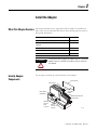
Chapter 2
Install the Adapter
What This Chapter Contains . . . . . . . . . . . . . . . . . . . . . . . . . . . . . . . . . . 9
Identify Adapter Components . . . . . . . . . . . . . . . . . . . . . . . . . . . . . . . . 9
Mount the Adapter on a DIN Rail Before Installing Modules . . . . . . 10
Mount (or Replace) the Adapter to an Existing System. . . . . . . . . . . . 11
Wire Your Adapter. . . . . . . . . . . . . . . . . . . . . . . . . . . . . . . . . . . . . . . . . 12
Mounting Dimensions . . . . . . . . . . . . . . . . . . . . . . . . . . . . . . . . . . . . . . 13
Chapter 3
Configure the Adapter for Your
EtherNet/IP Network
What This Chapter Contains . . . . . . . . . . . . . . . . . . . . . . . . . . . . . . . . . 15
IP Address . . . . . . . . . . . . . . . . . . . . . . . . . . . . . . . . . . . . . . . . . . . . 17
Gateway Address . . . . . . . . . . . . . . . . . . . . . . . . . . . . . . . . . . . . . . . 17
Subnet Mask. . . . . . . . . . . . . . . . . . . . . . . . . . . . . . . . . . . . . . . . . . . 18
Set the Network Address. . . . . . . . . . . . . . . . . . . . . . . . . . . . . . . . . . . . 19
Use the Rockwell BootP/DHCP Utility . . . . . . . . . . . . . . . . . . . . . . . . 20
Save the Relation List . . . . . . . . . . . . . . . . . . . . . . . . . . . . . . . . . . . 22
Use DHCP Software to Configure Your Adapter . . . . . . . . . . . . . . . . 23

Publication 1734-UM011D-EN-P - May 2011
xii
Chapter 4
Configure the Adapter for
Direct Connection in RSLogix
5000 Software
What This Chapter Contains . . . . . . . . . . . . . . . . . . . . . . . . . . . . . . . . . 25
Set Up the Hardware . . . . . . . . . . . . . . . . . . . . . . . . . . . . . . . . . . . . . . . 25
Create the Example Application . . . . . . . . . . . . . . . . . . . . . . . . . . . . . . 26
Configure the I/O . . . . . . . . . . . . . . . . . . . . . . . . . . . . . . . . . . . . . . . . . 27
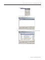
Add the Local EtherNet/IP Bridge to the I/O Configuration. . . 28
Add the POINT I/O Adapter to the I/O Configuration . . . . . . . 30
Add the POINT I/O Modules to the I/O Configuration . . . . . . 33
Edit the Controller Tags . . . . . . . . . . . . . . . . . . . . . . . . . . . . . . . . . . . . 38
Create the Ladder Program . . . . . . . . . . . . . . . . . . . . . . . . . . . . . . . . . . 39
Download the Program to the Controller. . . . . . . . . . . . . . . . . . . . . . . 39
Verify the Module Chassis Size . . . . . . . . . . . . . . . . . . . . . . . . . . . . . . . 41
Configure the Adapter with Fixed IP Address . . . . . . . . . . . . . . . . . . . 43
Recover From an Overloaded Adapter. . . . . . . . . . . . . . . . . . . . . . . . . 44
Chapter 5
Configure the Adapter for
Direct Connection and Rack
Optimization in RSLogix 5000
Software
What This Chapter Contains . . . . . . . . . . . . . . . . . . . . . . . . . . . . . . . . . 45
Create the Example Application . . . . . . . . . . . . . . . . . . . . . . . . . . . . . . 47
Configure the I/O Modules . . . . . . . . . . . . . . . . . . . . . . . . . . . . . . . . . 48
Add the Local EtherNet/IP Bridge to the I/O Configuration. . . 48
Add the POINT I/O Adapter to the I/O Configuration . . . . . . . 50
Add the POINT I/O Module and Configure for Direction
Connection. . . . . . . . . . . . . . . . . . . . . . . . . . . . . . . . . . . . . . . . . . . . 53
Add the POINT I/O Module and Configure For
Rack Optimization. . . . . . . . . . . . . . . . . . . . . . . . . . . . . . . . . . . . . . 55
Download the Program to the Controller. . . . . . . . . . . . . . . . . . . . . . . 58
Verify the Module Chassis Size . . . . . . . . . . . . . . . . . . . . . . . . . . . . . . . 59
Access Module Data. . . . . . . . . . . . . . . . . . . . . . . . . . . . . . . . . . . . . . . . 62
Chapter 6
LED Status Indicators
What This Chapter Contains . . . . . . . . . . . . . . . . . . . . . . . . . . . . . . . . . 63
Interpret the Status Indicators . . . . . . . . . . . . . . . . . . . . . . . . . . . 63
Appendix A
Adapter Web Pages
What This Appendix Contains . . . . . . . . . . . . . . . . . . . . . . . . . . . . . . . 67
Work with the Home Page . . . . . . . . . . . . . . . . . . . . . . . . . . . . . . . . . . 67
Work with the Diagnostics Pages . . . . . . . . . . . . . . . . . . . . . . . . . . . . . 69
Use the Diagnostic Overview Page. . . . . . . . . . . . . . . . . . . . . . . . . 70
Use the Network Settings Page. . . . . . . . . . . . . . . . . . . . . . . . . . . . 71
Use the Ethernet Statistics Page . . . . . . . . . . . . . . . . . . . . . . . . . . . 72
Use the I/O Connections Page. . . . . . . . . . . . . . . . . . . . . . . . . . . . 74
Use the Diagnostic Messaging Page . . . . . . . . . . . . . . . . . . . . . . . . 75
Work with the Configuration Pages . . . . . . . . . . . . . . . . . . . . . . . . . . . 76
Use the Identity Page. . . . . . . . . . . . . . . . . . . . . . . . . . . . . . . . . . . . 77
Use the Network Configuration Page. . . . . . . . . . . . . . . . . . . . . . . 78
Use the Services Page . . . . . . . . . . . . . . . . . . . . . . . . . . . . . . . . . . . 80
Work with the Browse Chassis Page . . . . . . . . . . . . . . . . . . . . . . . . . . . 80
Appendix B

Publication 1734-UM011D-EN-P - May 2011
xiii
Configure the RSLinx Ethernet
Communication Driver
What This Appendix Contains . . . . . . . . . . . . . . . . . . . . . . . . . . . . . . . 87
Install the RSLinx Software . . . . . . . . . . . . . . . . . . . . . . . . . . . . . . . . . . 87
Configure the AB_ETH/IP Driver . . . . . . . . . . . . . . . . . . . . . . . . . . . 88
Appendix C
1734 POINT I/O
Module/RSLogix 5000
Controller Tag Reference
What This Appendix Contains . . . . . . . . . . . . . . . . . . . . . . . . . . . . . . . 91
1734 POINT I/O Catalog Numbers . . . . . . . . . . . . . . . . . . . . . . . . . . 91
Valid Number Ranges for RSLogix 5000 Data Types . . . . . . . . . . . . . 92
Digital 2 POINT Input . . . . . . . . . . . . . . . . . . . . . . . . . . . . . . . . . . . . . 93
Digital 2 POINT Output – With Over Load and
Open Load Diagnostic Status . . . . . . . . . . . . . . . . . . . . . . . . . . . . . . . . 96
Digital 2 POINT Output – With Over
Load Diagnostic Status . . . . . . . . . . . . . . . . . . . . . . . . . . . . . . . . . . . . . 97
Digital 4 POINT Output – With Over
Load and Open Load Diagnostic Status . . . . . . . . . . . . . . . . . . . . . . . . 98
Digital 4 POINT Output – With Over
Load Diagnostic Status . . . . . . . . . . . . . . . . . . . . . . . . . . . . . . . . . . . . . 99
Analog 2 Channel Output . . . . . . . . . . . . . . . . . . . . . . . . . . . . . . . . . . 109
Appendix D
Quick Start
What This Appendix Contains . . . . . . . . . . . . . . . . . . . . . . . . . . . . . . 131
Necessary Prerequisites . . . . . . . . . . . . . . . . . . . . . . . . . . . . . . . . . 131
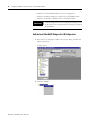
Configure the Adapter . . . . . . . . . . . . . . . . . . . . . . . . . . . . . . . . . . . . . 132
Enter Adapter Properties . . . . . . . . . . . . . . . . . . . . . . . . . . . . . . . 133
Add Another Module Under the Adapter . . . . . . . . . . . . . . . . . . 134
Configure 1734 POINT I/O Modules . . . . . . . . . . . . . . . . . . . . . . . . 135
Configure an Ethernet Driver in RSLinx Software . . . . . . . . . . . . . . 138
Launch RSLinx Software. . . . . . . . . . . . . . . . . . . . . . . . . . . . . . . . 138
Index

Publication 1734-UM011D-EN-P - May 2011
xiv
Notes:

xv Publication 1734-UM011D-EN-P - May 2011
Summary of Changes
This publication contains new and revised information not in the last release.
New and Revised Information
See the table for a summary of the major changes in this manual.
Change Bars
Change bars (as shown with this paragraph) show the areas in this manual that
are different from previous editions and indicate the addition of new or
revised information.
Chapter Revised to include
Appendix B - Configure the RSLinx
Ethernet Communication Driver
Removal of Ethernet device installation
instructions

Publication 1734-UM011D-EN-P - May 2011
xvi Summary of Changes
Notes:

1 Publication 1734-UM011D-EN-P - May 2011
Chapter
1
About the Adapter
What This Chapter Contains
This chapter provides an overview of the 1734-AENT POINT I/O
EtherNet/IP adapter, its primary features, and how to use it. You need to
understand the concepts discussed in this chapter to configure your adapter
and use it in an EtherNet/IP control system. See the table for a list of where to
find specific information in this chapter.
Important Adapter
Considerations
Before you begin using your adapter, note the following important
considerations.
Set the Chassis Size
The 1734-AENT POINT I/O adapter for EtherNet/IP requires
configuration of its chassis size before you can make any I/O connections.
Topic Page
Important Adapter Considerations 1
Set the Chassis Size 1
Adapter Replacement 2
Empty Slots and RIUP Situations 2
Cycle Power To a System For the First Time 4
Adapter Features 4
Hardware/Software Compatibility 5
What the Adapter Does 5
Use of the Common Industrial Protocol (CIP) 5
Understand the Producer/Consumer Model 6
Specify the Requested Packet Interval (RPI) 6
Support of Rack-optimized and Direct Connections 7
Mix Rack-optimized and Direct Connections 7
ATTENTION
You must use series C POINT I/O modules with the
1734-AENT adapter. Series A or B POINT I/O modules will
not work with this adapter.

Publication 1734-UM011D-EN-P - May 2011
2 About the Adapter
The default setting for the chassis size is 1 slot, which represents the adapter
by itself.
Set the chassis size as the sum of the slot of the adapter plus the slots of each
I/O module in the adapter backplane. For example, the adapter plus 4 I/O
modules uses a chassis size of 5. The adapter stores this chassis size setting in
non-volatile storage.
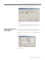
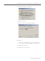
When the adapter’s non-volatile chassis size does not match the actual number
of modules present on its backplane, the adapter does not make any I/O
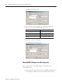
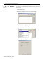
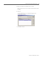
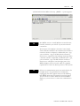
connections and an error occurs, as shown in the Module Properties dialog.
Adapter Replacement
It is important to note that during a connection request from the controller,
the chassis size setting for a 1734-AENT adapter is not communicated to the
adapter. You must always set this chassis size using a separate operation. This
includes situations when you are replacing an adapter. The adapter does not
make any I/O connections until it is configured with the appropriate chassis
size.
Empty Slots and RIUP Situations
The POINT I/O system does not have the ability to detect an empty terminal
base. Because of this, there are numerous situations in which you can
potentially configure a system that is unusable or one that exercises unintended
control.
In an attempt to address these situations, you must observe the following rules
for POINT I/O system construction and the removal and reinsertion of
modules:

Publication 1734-UM011D-EN-P - May 2011
About the Adapter 3
• A correct POINT I/O system does not have any empty terminal bases.
• After you cycle power, the adapter does not run any I/O until the
number of modules comprising the chassis equals the stored chassis
size.
– Because the adapter cannot detect empty terminal bases, it cannot
assume any safe operation until there is a match between the number
of modules indicating their presence in the chassis and what the
adapter has saved in non-volatile memory.
– Actual module identification (such as, electronic keying) is done
when connection establishment requests are received from the
controller or controllers.
• A module removed under power does not disrupt operation of the other
I/O modules.
– When you remove a module, the adapter determines what changed.
– Whenever you remove a module with an active connection from the
POINT I/O system, the adapter indicates this by flashing the
POINTBus Status LED red and reports a minor recoverable fault.
• If more than one contiguous module is removed under power,
connections to all modules in the contiguous missing module set are
disallowed until all modules are replaced. Because the adapter cannot
detect an empty base, it does not know the physical positioning of the
modules until all the missing modules are replaced.
• If a module separating two sets of contiguous missing modules is
removed, the two sets merge into a single set. All the modules must be
replaced before connections are permitted to any module in the set.
• If modules of different types are removed and returned to the wrong
locations, attempts to connect to these modules fail during verification
of the electronic ID (providing that keying has not been disabled).
• If modules of the same type are removed and returned to the wrong
locations, they accept connections from the controller or controllers and
reconfigure with the correct data once they pass their electronic keying
check.
• These removal and return conditions apply whether the system is under
power or not. If the system is under power, the situation arises
immediately. If the system is not under power, the situation arises in the
next power cycle.

Publication 1734-UM011D-EN-P - May 2011
4 About the Adapter
Cycle Power To a System for the First Time
When you cycle power to the POINT I/O for the first time, the adapter must
assign addresses to every module in the backplane. POINT I/O modules all
ship configured at the same address.
When you first apply power, we expect that all but one module on the
backplane exhibits a solid red Module Status LED.
One by one the adapter resets these modules and addresses them
appropriately. The amount of time that this operation takes is proportional to
the size of your POINT I/O system.
Adapter Features
The 1734-AENT adapter has the following features:
• EtherNet/IP messages encapsulated within standard TCP/UDP/IP
protocol
• Common application layer with ControlNet and DeviceNet networks
• Interfacing via Category 5 rated twisted pair cable
• Half/full duplex 10 Mbit or 100 Mbit operation
• DIN rail mounting
• Communication to and from other POINT I/O modules on the same
DIN rail
• Communication supported by RSLinx software
• IP address assigned via standard BootP or DHCP tools
• I/O configuration via RSLogix 5000 software
• No network scheduling required
• No routing tables required
• Support of connections from multiple controllers simultaneously
Page is loading ...
Page is loading ...
Page is loading ...
Page is loading ...
Page is loading ...
Page is loading ...
Page is loading ...
Page is loading ...
Page is loading ...
Page is loading ...
Page is loading ...
Page is loading ...
Page is loading ...
Page is loading ...
Page is loading ...
Page is loading ...
Page is loading ...
Page is loading ...
Page is loading ...
Page is loading ...
Page is loading ...
Page is loading ...
Page is loading ...
Page is loading ...
Page is loading ...
Page is loading ...
Page is loading ...
Page is loading ...
Page is loading ...
Page is loading ...
Page is loading ...
Page is loading ...
Page is loading ...
Page is loading ...
Page is loading ...
Page is loading ...
Page is loading ...
Page is loading ...
Page is loading ...
Page is loading ...
Page is loading ...
Page is loading ...
Page is loading ...
Page is loading ...
Page is loading ...
Page is loading ...
Page is loading ...
Page is loading ...
Page is loading ...
Page is loading ...
Page is loading ...
Page is loading ...
Page is loading ...
Page is loading ...
Page is loading ...
Page is loading ...
Page is loading ...
Page is loading ...
Page is loading ...
Page is loading ...
Page is loading ...
Page is loading ...
Page is loading ...
Page is loading ...
Page is loading ...
Page is loading ...
Page is loading ...
Page is loading ...
Page is loading ...
Page is loading ...
Page is loading ...
Page is loading ...
Page is loading ...
Page is loading ...
Page is loading ...
Page is loading ...
Page is loading ...
Page is loading ...
Page is loading ...
Page is loading ...
Page is loading ...
Page is loading ...
Page is loading ...
Page is loading ...
Page is loading ...
Page is loading ...
Page is loading ...
Page is loading ...
Page is loading ...
Page is loading ...
Page is loading ...
Page is loading ...
Page is loading ...
Page is loading ...
Page is loading ...
Page is loading ...
Page is loading ...
Page is loading ...
Page is loading ...
Page is loading ...
Page is loading ...
Page is loading ...
Page is loading ...
Page is loading ...
Page is loading ...
Page is loading ...
Page is loading ...
Page is loading ...
Page is loading ...
Page is loading ...
Page is loading ...
Page is loading ...
Page is loading ...
Page is loading ...
Page is loading ...
Page is loading ...
Page is loading ...
Page is loading ...
Page is loading ...
Page is loading ...
Page is loading ...
Page is loading ...
Page is loading ...
Page is loading ...
Page is loading ...
Page is loading ...
Page is loading ...
Page is loading ...
Page is loading ...
Page is loading ...
Page is loading ...
Page is loading ...
Page is loading ...
Page is loading ...
Page is loading ...
Page is loading ...
Page is loading ...
Page is loading ...
-
 1
1
-
 2
2
-
 3
3
-
 4
4
-
 5
5
-
 6
6
-
 7
7
-
 8
8
-
 9
9
-
 10
10
-
 11
11
-
 12
12
-
 13
13
-
 14
14
-
 15
15
-
 16
16
-
 17
17
-
 18
18
-
 19
19
-
 20
20
-
 21
21
-
 22
22
-
 23
23
-
 24
24
-
 25
25
-
 26
26
-
 27
27
-
 28
28
-
 29
29
-
 30
30
-
 31
31
-
 32
32
-
 33
33
-
 34
34
-
 35
35
-
 36
36
-
 37
37
-
 38
38
-
 39
39
-
 40
40
-
 41
41
-
 42
42
-
 43
43
-
 44
44
-
 45
45
-
 46
46
-
 47
47
-
 48
48
-
 49
49
-
 50
50
-
 51
51
-
 52
52
-
 53
53
-
 54
54
-
 55
55
-
 56
56
-
 57
57
-
 58
58
-
 59
59
-
 60
60
-
 61
61
-
 62
62
-
 63
63
-
 64
64
-
 65
65
-
 66
66
-
 67
67
-
 68
68
-
 69
69
-
 70
70
-
 71
71
-
 72
72
-
 73
73
-
 74
74
-
 75
75
-
 76
76
-
 77
77
-
 78
78
-
 79
79
-
 80
80
-
 81
81
-
 82
82
-
 83
83
-
 84
84
-
 85
85
-
 86
86
-
 87
87
-
 88
88
-
 89
89
-
 90
90
-
 91
91
-
 92
92
-
 93
93
-
 94
94
-
 95
95
-
 96
96
-
 97
97
-
 98
98
-
 99
99
-
 100
100
-
 101
101
-
 102
102
-
 103
103
-
 104
104
-
 105
105
-
 106
106
-
 107
107
-
 108
108
-
 109
109
-
 110
110
-
 111
111
-
 112
112
-
 113
113
-
 114
114
-
 115
115
-
 116
116
-
 117
117
-
 118
118
-
 119
119
-
 120
120
-
 121
121
-
 122
122
-
 123
123
-
 124
124
-
 125
125
-
 126
126
-
 127
127
-
 128
128
-
 129
129
-
 130
130
-
 131
131
-
 132
132
-
 133
133
-
 134
134
-
 135
135
-
 136
136
-
 137
137
-
 138
138
-
 139
139
-
 140
140
-
 141
141
-
 142
142
-
 143
143
-
 144
144
-
 145
145
-
 146
146
-
 147
147
-
 148
148
-
 149
149
-
 150
150
-
 151
151
-
 152
152
-
 153
153
-
 154
154
-
 155
155
-
 156
156
-
 157
157
-
 158
158


Allen-Bradley Rockwell Automation 1734-AENT User manual
- Category
- Networking
- Type
- User manual
- This manual is also suitable for
Ask a question and I''ll find the answer in the document
Finding information in a document is now easier with AI
Related papers
-
Allen-Bradley Rockwell Automation 1734-AENT Installation Instructions Manual
-
-
-
-
-
-
Allen-Bradley 1769-L18ERM-BB1B User manual
-
-
-
Other documents
-
Bradley Smoker 1734-AENT User manual
-
 Rockwell Automation Allen-Bradley EtherNet/IP User manual
-
Rockwell Automation 1768-L43 Quick start guide
-
 Rockwell Automation Allen-Bradley ControlNet 1756-CNB User manual
-
 Rockwell Automation Allen-Bradley GuardLogix Application Technique
-
 Rockwell Automation Allen-Bradley 836P Series User manual
-
 ProSoft Technology ILX34-MBS232 User manual
-
 Rockwell Automation Allen-Bradley 1756-EWEB Installation Instructions Manual
-
 Rockwell Automation Allen-Bradley 42AF-R1MAB1-F4 User manual
-
Rockwell Automation Allen-Bradley GuardLogix 5570 Application Technique


