Page is loading ...

POINT I/O Synchronous Serial Interface Absolute Encoder Module
Catalog Number 1734-SSI
User Manual

Important User Information
Read this document and the documents listed in the additional resources section about installation, configuration, and
operation of this equipment before you install, configure, operate, or maintain this product. Users are required to
familiarize themselves with installation and wiring instructions in addition to requirements of all applicable codes, laws,
and standards.
Activities including installation, adjustments, putting into service, use, assembly, disassembly, and maintenance are required
to be carried out by suitably trained personnel in accordance with applicable code of practice.
If this equipment is used in a manner not specified by the manufacturer, the protection provided by the equipment may be
impaired.
In no event will Rockwell Automation, Inc. be responsible or liable for indirect or consequential damages resulting from the
use or application of this equipment.
The examples and diagrams in this manual are included solely for illustrative purposes. Because of the many variables and
requirements associated with any particular installation, Rockwell Automation, Inc. cannot assume responsibility or
liability for actual use based on the examples and diagrams.
No patent liability is assumed by Rockwell Automation, Inc. with respect to use of information, circuits, equipment, or
software described in this manual.
Reproduction of the contents of this manual, in whole or in part, without written permission of Rockwell Automation,
Inc., is prohibited.
Throughout this manual, when necessary, we use notes to make you aware of safety considerations.
Labels may also be on or inside the equipment to provide specific precautions.
Allen-Bradley, Rockwell Software, and Rockwell Automation are trademarks of Rockwell Automation, Inc.
Trademarks not belonging to Rockwell Automation are property of their respective companies.
WARNING: Identifies information about practices or circumstances that can cause an explosion in a hazardous environment,
which may lead to personal injury or death, property damage, or economic loss.
ATTENTION: Identifies information about practices or circumstances that can lead to personal injury or death, property
damage, or economic loss. Attentions help you identify a hazard, avoid a hazard, and recognize the consequence.
IMPORTANT
Identifies information that is critical for successful application and understanding of the product.
SHOCK HAZARD: Labels may be on or inside the equipment, for example, a drive or motor, to alert people that dangerous
voltage may be present.
BURN HAZARD: Labels may be on or inside the equipment, for example, a drive or motor, to alert people that surfaces may
reach dangerous temperatures.
ARC FLASH HAZARD: Labels may be on or inside the equipment, for example, a motor control center, to alert people to
potential Arc Flash. Arc Flash will cause severe injury or death. Wear proper Personal Protective Equipment (PPE). Follow ALL
Regulatory requirements for safe work practices and for Personal Protective Equipment (PPE).

Rockwell Automation Publication 1734-UM007E-EN-P - October 2015 3
Summary of Changes
This manual contains new and updated information. Changes throughout this
revision are marked by change bars, as shown to the right of this paragraph.
New and Updated
Information
This table contains the changes made to this revision.
Topic Page
Updated Parameters 12, 13, and 14 in Parameter Object table. 24

4 Rockwell Automation Publication 1734-UM007E-EN-P - October 2015
Summary of Changes
Notes:

Rockwell Automation Publication 1734-UM007E-EN-P - October 2015 5
Table of Contents
Preface
Purpose of This Manual . . . . . . . . . . . . . . . . . . . . . . . . . . . . . . . . . . . . . . . 7
Who Should Use This Manual . . . . . . . . . . . . . . . . . . . . . . . . . . . . . . . . . . . . . . 7
Additional Resources . . . . . . . . . . . . . . . . . . . . . . . . . . . . . . . . . . . . . . . . . . . . . . . 7
Chapter 1
Install the Module
About This Chapter. . . . . . . . . . . . . . . . . . . . . . . . . . . . . . . . . . . . . . . . . . . . . . . . 9
About the Module . . . . . . . . . . . . . . . . . . . . . . . . . . . . . . . . . . . . . . . . . . . . . . . . . 9
Install the Mounting Base. . . . . . . . . . . . . . . . . . . . . . . . . . . . . . . . . . . . . . . . . 10
Install the Module. . . . . . . . . . . . . . . . . . . . . . . . . . . . . . . . . . . . . . . . . . . . . . . . 11
Install the Removable Terminal Block . . . . . . . . . . . . . . . . . . . . . . . . . . . . . 12
Remove a Mounting Base . . . . . . . . . . . . . . . . . . . . . . . . . . . . . . . . . . . . . . . . . 13
Wire the Module. . . . . . . . . . . . . . . . . . . . . . . . . . . . . . . . . . . . . . . . . . . . . . . . . 13
Chapter 2
Configure the Module
About This Chapter. . . . . . . . . . . . . . . . . . . . . . . . . . . . . . . . . . . . . . . . . . . . . . 15
Add the Adapter to Your Network . . . . . . . . . . . . . . . . . . . . . . . . . . . . . . . . 15
Add I/O Modules to Your Network . . . . . . . . . . . . . . . . . . . . . . . . . . . . . . . 16
Set the Encoder’s Parameters . . . . . . . . . . . . . . . . . . . . . . . . . . . . . . . . . . . . . . 17
Check I/O Status and View the EDS File . . . . . . . . . . . . . . . . . . . . . . . . . . 19
Chapter 3
Communicate with Your Module
About This Chapter. . . . . . . . . . . . . . . . . . . . . . . . . . . . . . . . . . . . . . . . . . . . . . 21
About Communications. . . . . . . . . . . . . . . . . . . . . . . . . . . . . . . . . . . . . . . . . . 21
Communicate Real-time Information. . . . . . . . . . . . . . . . . . . . . . . . . . . . . . 22
Operating Modes . . . . . . . . . . . . . . . . . . . . . . . . . . . . . . . . . . . . . . . . . . . . . . . . 24
Chapter 4
Set and Operate Your Module
About This Chapter. . . . . . . . . . . . . . . . . . . . . . . . . . . . . . . . . . . . . . . . . . . . . . 27
Module Configuration Value Definitions . . . . . . . . . . . . . . . . . . . . . . . . . . 27
Operation of the Data Latch and Comparator Features . . . . . . . . . . . . . 28
Other Module Features. . . . . . . . . . . . . . . . . . . . . . . . . . . . . . . . . . . . . . . . . . . 31
Example of Using the 1734-SSI Module with a 24-bit SSI Sensor. . . . . 32
Chapter 5
Diagnose Problems
About This Chapter. . . . . . . . . . . . . . . . . . . . . . . . . . . . . . . . . . . . . . . . . . . . . . 35
Use the Indicators for Troubleshooting . . . . . . . . . . . . . . . . . . . . . . . . . . . . 35

6 Rockwell Automation Publication 1734-UM007E-EN-P - October 2015
Table of Contents
Appendix A
Configure Modules in RSLogix 5000
Software
About This Appendix . . . . . . . . . . . . . . . . . . . . . . . . . . . . . . . . . . . . . . . . . . . . 37
Understand Data, Connection, and Communication Formats . . . . . . . 37
Configure Your Module . . . . . . . . . . . . . . . . . . . . . . . . . . . . . . . . . . . . . . . . . . 38
Use the Help Button . . . . . . . . . . . . . . . . . . . . . . . . . . . . . . . . . . . . . . . . . . . . . 38
Work with the Feedback Dialog . . . . . . . . . . . . . . . . . . . . . . . . . . . . . . . . . . . 39
Work with the Conversion Dialog . . . . . . . . . . . . . . . . . . . . . . . . . . . . . . . . . 40
Work with the Input Registration Dialog. . . . . . . . . . . . . . . . . . . . . . . . . . . 41
Work with the Watch Position Dialog . . . . . . . . . . . . . . . . . . . . . . . . . . . . . 42
Index

Rockwell Automation Publication 1734-UM007E-EN-P - October 2015 7
Preface
Purpose of This Manual
Read this manual for information about how to install, configure, and
troubleshoot your module.
Who Should Use This Manual
You must be able to use RSNetWorx software or similar configuration software
to set up and calibrate these modules. You must have the capability to download
and use electronic data sheet files.
In this manual, we assume you know how to perform these tasks. If you do not,
refer to your software user manuals or online help before attempting to use these
modules.
Additional Resources
For specification, safety approval, and other information, refer to POINT I/O
Synchronous Serial Interface Absolute Encoder Module Installation Instructions,
publication 1734-IN581
.
These documents contain additional information concerning related products
from Rockwell Automation.
For This Information See
Install the Module Chapter 1
Configure the Module Chapter 2
Communicate with Your Module Chapter 3
Set and Operate Your Module Chapter 4
Diagnose Problems Chapter 5
Configure Modules in RSLogix 5000 software Appendix A
Description Cat. No. Publication
Analog Input Modules
Installation Instructions
1734-IE2C
17340IE2V
1734-IN027
Analog Output Modules
Installation Instructions
1734-OE2C
1734-OE2V
1734-IN002
DeviceNet Communication Interface
Installation Instructions
1734-PDN 1734-IN057
Field Potential Distributor
Installation Instructions
1734-FPD 1734-IN059
POINT I/O 24V DC Expansion Power Supply
Installation Instructions
1734-EP24DC 1734-IN058
POINT I/O Selection Guide 1734 series 1734-SG001
Protected Output Modules
Installation Instructions
1734-OB2E
1734-OB4E
1734-OB8E
1734-IN056
Relay Output Modules
Installation Instructions
1734-OW2
1734-OW4
1734-IN055
Sink Input Modules
Installation Instructions
1734-IB2
1734-IB4
1734-IB8
1734-IN051

8 Rockwell Automation Publication 1734-UM007E-EN-P - October 2015
Preface
You can view or download publications at
http:/www.rockwellautomation.com/literature/
. To order paper copies of
technical documentation, contact your local Allen-Bradley distributor or
Rockwell Automation sales representative.
Source Output Modules
Installation Instructions
1734-IV2
1734-IV4
1734-IV8
1734-IN052
Very High-speed Counter Modules
Installation Instructions
1734-VHSC5
1734-VHSC24
1734-IN003
Wiring Base Assembly
Installation Instructions
1734-TB
1734-TBS
1734-IN511
Wiring Base Assembly
Installation Instructions
1734-TB3
1734-TB3S
1734-IN013
Description Cat. No. Publication

Rockwell Automation Publication 1734-UM007E-EN-P - October 2015 9
Chapter 1
Install the Module
About This Chapter
Read this chapter to learn about how to install, wire, and remove the 1734-SSI
module.
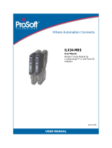
About the Module
The 1734-SSI module collects serial data from industrial absolute-position
encoding sensors that use a standard SSI protocol.
Description Description
1 Module locking mechanism 6 Slide-in writable label
2 Module wiring diagram 7 Insertable I/O module
3 DIN rail locking screw (orange) 8 Removable terminal block handle
4 Mechanical keying (orange) 9 Removable terminal block
5 Interlocking side pieces 10 Mounting base
NODE:
1734
SSI
1
2
3
4
5
6
7
8
9
10

10 Rockwell Automation Publication 1734-UM007E-EN-P - October 2015
Chapter 1 Install the Module
Insert the module into a POINT I/O terminal base that provides common
power, communication, and wiring connections for the SSI sensors. Use this
Series C module with the following.
• ControlNet adapter
with RSLogix 5000 software, version 11 or later
• DeviceNet adapter
• EtherNet/IP adapter
with RSLogix 5000 software, version 11 or later
• PROFIBUS adapter
Install the Mounting Base
The wiring base assembly (1734-TB or 1734-TBS) consists of a mounting base
(1734-MB) and a removable terminal block (1734-RTB or 1734-RTBS). You can
install the assembly, or just the mounting base. To install the mounting base/
wiring base assembly on the DIN rail, proceed as follows.
1. Position the mounting base/wiring base assembly vertically above the
installed units (adapter, power supply, or existing module).
2. Slide the mounting base down, allowing the interlocking side pieces to
engage the adjacent module or adapter.
ATTENTION: POINT I/O is grounded through the DIN rail to chassis ground. Use
zinc-plated yellow-chromate steel DIN rail to assure proper grounding. The use
of other DIN rail material (such as aluminum and plastic) that can corrode,
oxidize, or are poor conductors, can result in improper or intermittent
grounding. Secure DIN rail to mounting surface approximately every 200 mm
(7.8 in.) and use end-anchors appropriately.
Slide the mounting base to allow the
interlocking side pieces to engage the
adjacent module or adapter.

Rockwell Automation Publication 1734-UM007E-EN-P - October 2015 11
Install the Module Chapter 1
3. Press firmly to seat the mounting base on the DIN rail. The mounting base
snaps into place.
4. To remove the mounting base from the DIN rail, remove any installed
module (and any module immediately to the right), and use a small-bladed
screwdriver to rotate the DIN rail locking screw to a vertical position. This
releases the locking mechanism.
5. Lift straight up to remove the mounting base.
6. Repeat this procedure for the next mounting base assembly.
Install the Module
Install the module before or after base installation. Make sure that the mounting
base is correctly keyed before installing the module into the mounting base. In
addition, make sure the mounting base locking screw is horizontal referenced to
the base.
1. Using a bladed screwdriver, rotate the keyswitch on the mounting base
clockwise till the number required for the type of module being installed
aligns with the notch in the base.
2. Make sure the DIN-rail locking screw is in the horizontal position, noting
that you cannot insert the module if the locking mechanism is unlocked.
NODE:
1734
SSI
Turn the keyswitch to align the number
with the notch. Position 3 is shown here.
1734-SSI uses keyswitch position 2.
Make sure the DIN-rail locking
screw is in the horizontal position.

12 Rockwell Automation Publication 1734-UM007E-EN-P - October 2015
Chapter 1 Install the Module
3. Insert the module straight down into the mounting base.
4. Press to secure. The module locks into place.
Install the Removable
Terminal Block
A removable terminal block (RTB) comes with your mounting base assembly. To
remove, pull up on the RTB handle. This lets you remove and replace the
mounting base as necessary without removing any of the wiring.
To reinsert the removable terminal block, proceed as follows.
1. Insert the RTB end opposite the handle into the base unit. The end has a
curved section that engages with the mounting base.
2. Rotate the terminal block into the mounting base until it locks itself in
place.
NODE:
1734
SSI
WARNING: When you connect or disconnect the removable terminal block
(RTB) with field-side power applied, an electrical arc can occur. This could cause
an explosion in hazardous location installations.
Be sure that power is removed or the area is nonhazardous before proceeding.
Hook the RTB end in to the
mounting base end, and rotate
until it locks into place.

Rockwell Automation Publication 1734-UM007E-EN-P - October 2015 13
Install the Module Chapter 1
3. If an I/O module is installed, snap the RTB handle into place on the
module.
Remove a Mounting Base
To remove a mounting base, you must remove any installed module, and the
module installed in the base to the right. Remove the removable terminal block,
if wired.
1. Unlatch the RTB handle on the I/O module.
2. Pull on the RTB handle to remove the removable terminal block.
3. Press in on the module lock on the top of the module.
4. Pull up on the I/O module to remove from the base.
5. Remove the module to the right of the base you are removing. The
interlocking portion of the base sits under the adjacent module.
6. Use a small-bladed screwdriver to rotate the orange DIN-rail locking screw
on the mounting base to a vertical position. This releases the locking
mechanism.
7. Lift the mounting base straight up to remove.
WARNING: When you connect or disconnect the removable terminal block
(RTB) with field-side power applied, an electrical arc can occur. This could cause
an explosion in hazardous location installations.
Be sure that power is removed or the area is nonhazardous before proceeding.
WARNING: When you insert or remove the module while backplane power is
on, an electrical arc can occur. This could cause an explosion in hazardous
location installations.
Be sure that power is removed or the area is nonhazardous before proceeding.
Repeated electrical arcing causes excessive wear to contacts on both the module
and its mating connector. Worn contacts may create electrical resistance that can
affect module operation.

14 Rockwell Automation Publication 1734-UM007E-EN-P - October 2015
Chapter 1 Install the Module
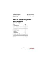
Wire the Module
Read this section for information about wiring the module.
WARNING: If you connect or disconnect wiring while the field-side power is on,
an electrical arc can occur. This could cause an explosion in hazardous location
installations. Be sure that power is removed or the area is nonhazardous before
proceeding.
Module
Status
Network
Status
1734
SSI
NODE:
RUN
UP
I1
DOWN
COMP
Module status
Network status
Run status
Up status
Down status
Comp status
D+
V+
Shield
C+
D-
V-
I1
C-
D = Data
I1 = Digital Sourcing Input 1
C = Clock
V = SSI Sensor
Module Terminations
0D+
(1)
1D-
(1)
2V+
3V-
4Shield
5I1
6C+
(1)
7C-
(1)
1 D and C are RS422-type differential pairs.
D+
V+
Shield
C+
D-
V-
I1
C-
01
23
45
67
I1

Rockwell Automation Publication 1734-UM007E-EN-P - October 2015 15
Chapter 2
Configure the Module
About This Chapter
Read this chapter for information about how to use RSNetWorx for DeviceNet
software to configure your module. You can configure the module while it is
online or offline.
This chapter shows configuration in the online mode. Configuration dialogs
appear similar in both modes. The primary difference is that if you make changes
offline, you must go online before the configuration changes take effect.
Add the Adapter to Your
Network
To add the adapter to your network, follow these steps.
1. Start the RSNetWorx for DeviceNet software.
2. Add the communication device as shown, noting that in this case, the
chosen device was a 1734-ADN DeviceNet adapter.
1. Click the “+” here to expand the
list of communication adapters.
2. Double-click the 1734-ADN
DeviceNet adapter. (You can also
click and drag the adapter name
onto the network.)
The scanner appears on the network.

16 Rockwell Automation Publication 1734-UM007E-EN-P - October 2015
Chapter 2 Configure the Module
Add I/O Modules to Your
Network
After you add the communication device, you must add the POINT I/O
modules connected to the scanner on the POINTBus backplane, using this
procedure.
1. Add modules as shown in the figure.
The out-of-the-box node setting for 1734 modules is 63. You can change
the setting by using the node commissioning tool. The node
commissioning tool is available either online or offline.
2. Double-click the module to change the node address.
1. Click the “+” here to expand the
list of specialty modules.
2. Double-click the catalog number
to choose the module. (You can
also click and drag the module
name onto the network.)
IMPORTANT
If you commission a node online, you must power down your system before the
change takes place.

Rockwell Automation Publication 1734-UM007E-EN-P - October 2015 17
Configure the Module Chapter 2
Set the Encoder’s Parameters
After adding the module to the network, you must configure the module for use.
1. Configure the modules as shown in the figure.
You see a dialog with a series of tabs. Each tab provides options to view or
edit.
IMPORTANT
This chapter shows configuration in the online mode. Changes set in this mode
take effect when you download to the individual module.
1. Click the module to highlight it.
2. From the Device menu, choose
Properties. (You can also right-
click the module or name, and the
property dialog pops up.)
These are the tabs you click
to view the options.

18 Rockwell Automation Publication 1734-UM007E-EN-P - October 2015
Chapter 2 Configure the Module
2. Refer to the dialogs for an explanation of features.
Use this menu to edit or view
the parameters.
Available choices are:
The module’s name appears here.
Type a description here.
The module’s address appears here.
(This field is read only.)
This dialog also shows the
module’s device identity.
These fields are read only.
Click the Device parameters tab
to get to the dialog for setting
the parameters.
At any point, you can click here to finish
changing configuration parameters.
If configuration changes are made in
offline mode, they do not take effect until
the system goes online.
This dialog appears after you click the Device
parameters tab. If you want the existing
parameters uploaded from the module, click
Upload. The following dialog then shows the
existing parameters set on the module.
Parameters tab
Configuration tab

Rockwell Automation Publication 1734-UM007E-EN-P - October 2015 19
Configure the Module Chapter 2
Check I/O Status and View
the EDS File
You can view the I/O defaults setup, and the EDS file by clicking the appropriate
tab.
To configure your module,
select Configuration and
modify the parameters as
desired for your application.
Click OK when finished.
Click the I/O Data tab to display
the default characteristics for this
module.
This dialog shows the input/output
defaults for the three modes.
These are:
• Polled
• Change of state
• Cyclic

20 Rockwell Automation Publication 1734-UM007E-EN-P - October 2015
Chapter 2 Configure the Module
Click the EDS File tab to display
the statistics of the EDS file used
to configure this module.
Click View File to view
the actual EDS file.
You can view the actual
EDS file or edit the file.
/