Allen-Bradley 1769-L18ERM-BB1B User manual
- Category
- Networking
- Type
- User manual

CompactLogix 5370 Controllers
Catalog Numbers 1769-L16ER-BB1B, 1769-L18ER-BB1B, 1769-L18ERM-BB1B, 1769-L19ER-BB1B, 1769-L24ER-QB1B, 1769-L24ER-
QBFC1B, 1769-L27ERM-QBFC1B, 1769-L30ER, 1769-L30ER-NSE, 1769-L30ERM, 1769-L33ER, 1769-L33ERM, 1769-L36ERM
User Manual
Для уменьшения размера файла удалены фотографии обложки и пустые страницы между разделами

Rockwell Automation Publication 1769-UM021G-EN-P - October 2015 3
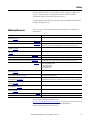
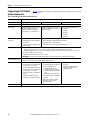
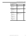
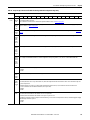
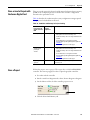
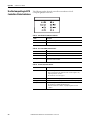
Summary of Changes
This manual contains new and updated information. Changes throughout this
revision are marked by change bars, as shown to the right of this paragraph.
Topic Page
Added 1769-L19ER-BB1B information Throughout
document
Added section Install the Removable Terminal Block 25
Added section Install the Removable Terminal Block 49
Added section Install the Removable Terminal Block 64
Updated the information on depleting stored energy from the 1769-L30ER-NSE 118

Rockwell Automation Publication 1769-UM021G-EN-P - October 2015 5
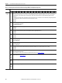
Table of Contents
Preface
Additional Resources . . . . . . . . . . . . . . . . . . . . . . . . . . . . . . . . . . . . . . . . . . . . . 11
Chapter 1
Install the CompactLogix 5370 L1
Controller
Before You Begin . . . . . . . . . . . . . . . . . . . . . . . . . . . . . . . . . . . . . . . . . . . . . . . . 16
CompactLogix 5370 L1 Controller Parts. . . . . . . . . . . . . . . . . . . . . . . 18
Installation Summary. . . . . . . . . . . . . . . . . . . . . . . . . . . . . . . . . . . . . . . . . . . . . 18
Install the Secure Digital Card . . . . . . . . . . . . . . . . . . . . . . . . . . . . . . . . . . . . 19
Install the System . . . . . . . . . . . . . . . . . . . . . . . . . . . . . . . . . . . . . . . . . . . . . . . . 21
Mount the System. . . . . . . . . . . . . . . . . . . . . . . . . . . . . . . . . . . . . . . . . . . . 21
Ground the System . . . . . . . . . . . . . . . . . . . . . . . . . . . . . . . . . . . . . . . . . . . 24
Install the Controller . . . . . . . . . . . . . . . . . . . . . . . . . . . . . . . . . . . . . . . . . 24
Install the Removable Terminal Block. . . . . . . . . . . . . . . . . . . . . . . . . . 25
Connect Power to the Controller (Series B) . . . . . . . . . . . . . . . . . . . . 26
Connect to the Controller via a USB Cable . . . . . . . . . . . . . . . . . . . . . . . . 31
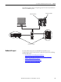
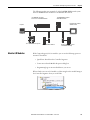
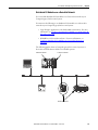
Connect the Controller to an EtherNet/IP Network. . . . . . . . . . . . . . . . 32
Connecting to Different EtherNet/IP Network Topologies. . . . . . 32
Chapter 2
Install the CompactLogix 5370 L2
Controller
Before You Begin . . . . . . . . . . . . . . . . . . . . . . . . . . . . . . . . . . . . . . . . . . . . . . . . 36
CompactLogix 5370 L2 Controller Parts. . . . . . . . . . . . . . . . . . . . . . . 37
Installation Summary. . . . . . . . . . . . . . . . . . . . . . . . . . . . . . . . . . . . . . . . . . . . . 37
Install the Secure Digital Card . . . . . . . . . . . . . . . . . . . . . . . . . . . . . . . . . . . . 38
Install the System . . . . . . . . . . . . . . . . . . . . . . . . . . . . . . . . . . . . . . . . . . . . . . . . 40
Mount the System. . . . . . . . . . . . . . . . . . . . . . . . . . . . . . . . . . . . . . . . . . . . 40
Ground the System . . . . . . . . . . . . . . . . . . . . . . . . . . . . . . . . . . . . . . . . . . . 46
Install the Controller . . . . . . . . . . . . . . . . . . . . . . . . . . . . . . . . . . . . . . . . . 47
Install the Removable Terminal Block. . . . . . . . . . . . . . . . . . . . . . . . . . 49
Wire the Terminal Block. . . . . . . . . . . . . . . . . . . . . . . . . . . . . . . . . . . . . . 49
Wire Size and Terminal Screw Torque . . . . . . . . . . . . . . . . . . . . . . . . . 50
Connect Power to the Control System . . . . . . . . . . . . . . . . . . . . . . . . . 50
Connect to the Controller via a USB Cable . . . . . . . . . . . . . . . . . . . . . . . . 53
Connect the Controller to an EtherNet/IP Network. . . . . . . . . . . . . . . . 54
Connecting to Different EtherNet/IP Network Topologies. . . . . . 54

6 Rockwell Automation Publication 1769-UM021G-EN-P - October 2015
Table of Contents
Chapter 3
Install the CompactLogix 5370 L3
Controller
Before You Begin. . . . . . . . . . . . . . . . . . . . . . . . . . . . . . . . . . . . . . . . . . . . . . . . . 58
CompactLogix 5370 L3 Controller Parts . . . . . . . . . . . . . . . . . . . . . . . 59
Installation Summary . . . . . . . . . . . . . . . . . . . . . . . . . . . . . . . . . . . . . . . . . . . . . 60
Install the Secure Digital Card. . . . . . . . . . . . . . . . . . . . . . . . . . . . . . . . . . . . . 60
Install the System. . . . . . . . . . . . . . . . . . . . . . . . . . . . . . . . . . . . . . . . . . . . . . . . . 62
Assemble the System . . . . . . . . . . . . . . . . . . . . . . . . . . . . . . . . . . . . . . . . . . 62
Install the Removable Terminal Block . . . . . . . . . . . . . . . . . . . . . . . . . . 64
Wire the Terminal Block . . . . . . . . . . . . . . . . . . . . . . . . . . . . . . . . . . . . . . 64
Wire Size and Terminal Screw Torque . . . . . . . . . . . . . . . . . . . . . . . . . 65
Mount the System . . . . . . . . . . . . . . . . . . . . . . . . . . . . . . . . . . . . . . . . . . . . 65
Ground the System . . . . . . . . . . . . . . . . . . . . . . . . . . . . . . . . . . . . . . . . . . . 69
Connect Power to the Control System . . . . . . . . . . . . . . . . . . . . . . . . . 71
Connect to the Controller via a USB Cable. . . . . . . . . . . . . . . . . . . . . . . . . 72
Connect the Controller to an EtherNet/IP Network . . . . . . . . . . . . . . . . 73
Connecting to Different EtherNet/IP Network Topologies . . . . . . 74
Chapter 4
Complete Software Tasks Required at
CompactLogix 5370 Controller
Installation
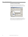
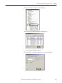
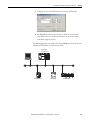
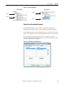
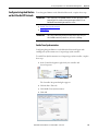
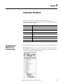
Set the IP Address of a Controller. . . . . . . . . . . . . . . . . . . . . . . . . . . . . . . . . . 77
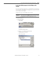
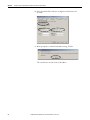
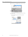
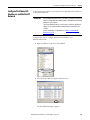
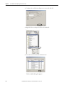
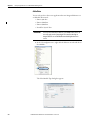
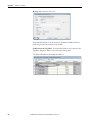
Use the BOOTP Server to Set the IP Address of the Controller . . 79
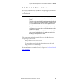
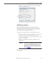
Use the DHCP Server to Set the IP Address of the Controller. . . . 86
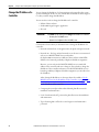
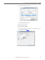
Use RSLinx Software to Set the IP Address of the Controller. . . . . 87
Use the Studio 5000 Environment to Set the IP Address of the
Controller . . . . . . . . . . . . . . . . . . . . . . . . . . . . . . . . . . . . . . . . . . . . . . . . . . . 89
Use the SD Card to Set the IP Address of the Controller. . . . . . . . . 93
Change the IP Address of a Controller . . . . . . . . . . . . . . . . . . . . . . . . . . . . . 94
Change the Network IP Address with RSLinx Classic Software. . . 95
Change the Network IP Address with an SD Card . . . . . . . . . . . . . . 97
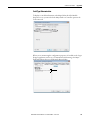
Load the Controller Firmware. . . . . . . . . . . . . . . . . . . . . . . . . . . . . . . . . . . . . 98
Use the ControlFLASH Software to Load Firmware . . . . . . . . . . . 104
Use AutoFlash to Load Firmware . . . . . . . . . . . . . . . . . . . . . . . . . . . . . 108
Use the Secure Digital Card to Load Firmware . . . . . . . . . . . . . . . . . 111
Select the Operating Mode of the Controller . . . . . . . . . . . . . . . . . . . . . . 112
Chapter 5
CompactLogix 5370 Controllers
Overview
CompactLogix 5370 Control System Components. . . . . . . . . . . . . . . . . 116
Controller Functionality . . . . . . . . . . . . . . . . . . . . . . . . . . . . . . . . . . . . . . . . . 117
Support for Integrated Motion over an EtherNet/IP Network. . . 118
Electronic Keying . . . . . . . . . . . . . . . . . . . . . . . . . . . . . . . . . . . . . . . . . . . . . . . 119
More Information . . . . . . . . . . . . . . . . . . . . . . . . . . . . . . . . . . . . . . . . . . . 119
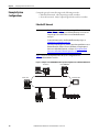
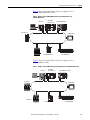
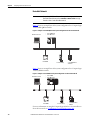
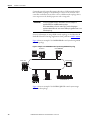
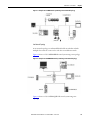
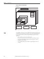
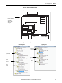
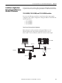
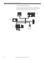
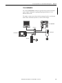
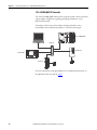
Example System Configurations . . . . . . . . . . . . . . . . . . . . . . . . . . . . . . . . . . 120
EtherNet/IP Network . . . . . . . . . . . . . . . . . . . . . . . . . . . . . . . . . . . . . . . 120
DeviceNet Network . . . . . . . . . . . . . . . . . . . . . . . . . . . . . . . . . . . . . . . . . 122

Rockwell Automation Publication 1769-UM021G-EN-P - October 2015 7
Table of Contents
Chapter 6
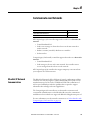
Communicate over Networks
EtherNet/IP Network Communication. . . . . . . . . . . . . . . . . . . . . . . . . . . 123
Available Software. . . . . . . . . . . . . . . . . . . . . . . . . . . . . . . . . . . . . . . . . . . 124
EtherNet/IP Network Functionality on CompactLogix 5370
Controllers . . . . . . . . . . . . . . . . . . . . . . . . . . . . . . . . . . . . . . . . . . . . . . . . . 124
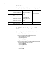
Nodes on an EtherNet/IP Network. . . . . . . . . . . . . . . . . . . . . . . . . . . 125
EtherNet/IP Network Topologies . . . . . . . . . . . . . . . . . . . . . . . . . . . . 127
Socket Interface with CompactLogix 5370 Controllers . . . . . . . . . 133
Quality of Service (QoS) and I/O Module Connections . . . . . . . . 133
EtherNet/IP Network Connections . . . . . . . . . . . . . . . . . . . . . . . . . . 134
DeviceNet Network Communication. . . . . . . . . . . . . . . . . . . . . . . . . . . . . 135
Available Software. . . . . . . . . . . . . . . . . . . . . . . . . . . . . . . . . . . . . . . . . . . 135
Compact I/O 1769-SDN DeviceNet Scanner. . . . . . . . . . . . . . . . . . 137
Power Supply Distance Rating. . . . . . . . . . . . . . . . . . . . . . . . . . . . . . . . 138
Current Capacity in CompactLogix 5370 L3 Control Systems . . 142
Chapter 7
Use I/O Modules with CompactLogix
5370 L1 Controllers
Select I/O Modules . . . . . . . . . . . . . . . . . . . . . . . . . . . . . . . . . . . . . . . . . . . . . 143
Connect Field Power to I/O Devices Connected to a CompactLogix
5730 L1 Control System . . . . . . . . . . . . . . . . . . . . . . . . . . . . . . . . . . . . . 144
Embedded I/O Modules . . . . . . . . . . . . . . . . . . . . . . . . . . . . . . . . . . . . . 149
Local Expansion Modules . . . . . . . . . . . . . . . . . . . . . . . . . . . . . . . . . . . . 158
Distributed I/O Modules over an EtherNet/IP Network . . . . . . . 162
Validate I/O Layout. . . . . . . . . . . . . . . . . . . . . . . . . . . . . . . . . . . . . . . . . . . . . 163
Set the Number of Local Expansion Modules . . . . . . . . . . . . . . . . . . 164
Empty Slots and Removal and Insertion Under Power Situations 165
Estimate Requested Packet Interval . . . . . . . . . . . . . . . . . . . . . . . . . . . 166
Module Faults Related to RPI Estimates. . . . . . . . . . . . . . . . . . . . . . . 168
Calculate System Power Consumption . . . . . . . . . . . . . . . . . . . . . . . . 168
Physical Placement of I/O Modules . . . . . . . . . . . . . . . . . . . . . . . . . . . 169
Use the Event Task. . . . . . . . . . . . . . . . . . . . . . . . . . . . . . . . . . . . . . . . . . . . . . 170
Configure I/O . . . . . . . . . . . . . . . . . . . . . . . . . . . . . . . . . . . . . . . . . . . . . . . . . . 174
Common Configuration Parameters . . . . . . . . . . . . . . . . . . . . . . . . . . 175
I/O Connections. . . . . . . . . . . . . . . . . . . . . . . . . . . . . . . . . . . . . . . . . . . . 175
Configure Distributed I/O Modules on an EtherNet/IP Network . . 176
Monitor I/O Modules. . . . . . . . . . . . . . . . . . . . . . . . . . . . . . . . . . . . . . . . . . . 179
Bus Off Detection and Recovery. . . . . . . . . . . . . . . . . . . . . . . . . . . . . . 181

8 Rockwell Automation Publication 1769-UM021G-EN-P - October 2015
Table of Contents
Chapter 8
Use I/O Modules with CompactLogix
5370 L2 Controllers
Select I/O Modules. . . . . . . . . . . . . . . . . . . . . . . . . . . . . . . . . . . . . . . . . . . . . . 183
Embedded I/O Modules . . . . . . . . . . . . . . . . . . . . . . . . . . . . . . . . . . . . . 184
Determine Embedded Module Update Time . . . . . . . . . . . . . . . . . . . . . . 198
Channel Update Times . . . . . . . . . . . . . . . . . . . . . . . . . . . . . . . . . . . . . . 198
Embedded Analog I/O Modules Data Arrays . . . . . . . . . . . . . . . . . . . . . . 204
Input Array . . . . . . . . . . . . . . . . . . . . . . . . . . . . . . . . . . . . . . . . . . . . . . . . . 204
Output Array . . . . . . . . . . . . . . . . . . . . . . . . . . . . . . . . . . . . . . . . . . . . . . . 206
Configuration Array . . . . . . . . . . . . . . . . . . . . . . . . . . . . . . . . . . . . . . . . . 207
Local Expansion Modules - Optional . . . . . . . . . . . . . . . . . . . . . . . . . . 214
Distributed I/O Modules over an EtherNet/IP Network. . . . . . . . 216
Distributed I/O Modules over a DeviceNet Network . . . . . . . . . . . 217
Validate I/O Layout . . . . . . . . . . . . . . . . . . . . . . . . . . . . . . . . . . . . . . . . . . . . . 218
Estimate Requested Packet Interval . . . . . . . . . . . . . . . . . . . . . . . . . . . 218
Module Fault Related to RPI Estimates. . . . . . . . . . . . . . . . . . . . . . . . 220
System Power Availability . . . . . . . . . . . . . . . . . . . . . . . . . . . . . . . . . . . . 220
Power Supply Distance Rating . . . . . . . . . . . . . . . . . . . . . . . . . . . . . . . . 221
Configure Local I/O Modules . . . . . . . . . . . . . . . . . . . . . . . . . . . . . . . . . . . . 224
Configure Embedded I/O Modules . . . . . . . . . . . . . . . . . . . . . . . . . . . 224
Configure Local Expansion Modules . . . . . . . . . . . . . . . . . . . . . . . . . . 225
Common Configuration Parameters . . . . . . . . . . . . . . . . . . . . . . . . . . 226
I/O Connections . . . . . . . . . . . . . . . . . . . . . . . . . . . . . . . . . . . . . . . . . . . . 227
Configure Distributed I/O Modules on an EtherNet/IP Network. . . 227
Configure Distributed I/O Modules on a DeviceNet Network . . . . . . 231
Monitor I/O Modules . . . . . . . . . . . . . . . . . . . . . . . . . . . . . . . . . . . . . . . . . . . 233
End Cap Detection and Module Faults . . . . . . . . . . . . . . . . . . . . . . . . 235
Chapter 9
Use I/O Modules with CompactLogix
5370 L3 Controllers
Select I/O Modules. . . . . . . . . . . . . . . . . . . . . . . . . . . . . . . . . . . . . . . . . . . . . . 237
Local Expansion Modules . . . . . . . . . . . . . . . . . . . . . . . . . . . . . . . . . . . . 238
Distributed I/O Modules over an EtherNet/IP Network. . . . . . . . 240
Distributed I/O Modules over a DeviceNet Network . . . . . . . . . . . 241
Validate I/O Layout . . . . . . . . . . . . . . . . . . . . . . . . . . . . . . . . . . . . . . . . . . . . . 242
Estimate Requested Packet Interval . . . . . . . . . . . . . . . . . . . . . . . . . . . 242
Module Fault Related to RPI Estimates. . . . . . . . . . . . . . . . . . . . . . . . 244
Calculate System Power Consumption . . . . . . . . . . . . . . . . . . . . . . . . 245
Physical Placement of I/O Modules . . . . . . . . . . . . . . . . . . . . . . . . . . . 248
Power Supply Distance Rating . . . . . . . . . . . . . . . . . . . . . . . . . . . . . . . . 251
Configure I/O . . . . . . . . . . . . . . . . . . . . . . . . . . . . . . . . . . . . . . . . . . . . . . . . . . 253
Common Configuration Parameters . . . . . . . . . . . . . . . . . . . . . . . . . . 254
I/O Connections . . . . . . . . . . . . . . . . . . . . . . . . . . . . . . . . . . . . . . . . . . . . 254
Configure Distributed I/O Modules on an EtherNet/IP Network. . . 255
Configure Distributed I/O Modules on a DeviceNet Network . . . . . . 258
Monitor I/O Modules . . . . . . . . . . . . . . . . . . . . . . . . . . . . . . . . . . . . . . . . . . . 260
End Cap Detection and Module Faults . . . . . . . . . . . . . . . . . . . . . . . . 262

Rockwell Automation Publication 1769-UM021G-EN-P - October 2015 9
Table of Contents
Chapter 10
Develop Applications
Elements of a Control Application . . . . . . . . . . . . . . . . . . . . . . . . . . . . . . . 263
Tasks. . . . . . . . . . . . . . . . . . . . . . . . . . . . . . . . . . . . . . . . . . . . . . . . . . . . . . . . . . . 264
Task Priority. . . . . . . . . . . . . . . . . . . . . . . . . . . . . . . . . . . . . . . . . . . . . . . . 267
Programs . . . . . . . . . . . . . . . . . . . . . . . . . . . . . . . . . . . . . . . . . . . . . . . . . . . . . . . 268
Scheduled and Unscheduled Programs . . . . . . . . . . . . . . . . . . . . . . . . 269
Routines . . . . . . . . . . . . . . . . . . . . . . . . . . . . . . . . . . . . . . . . . . . . . . . . . . . . . . . 270
Tags . . . . . . . . . . . . . . . . . . . . . . . . . . . . . . . . . . . . . . . . . . . . . . . . . . . . . . . . . . . 271
Extended Properties . . . . . . . . . . . . . . . . . . . . . . . . . . . . . . . . . . . . . . . . . 272
Access Extended Properties in Logic . . . . . . . . . . . . . . . . . . . . . . . . . . 273
Programming Languages. . . . . . . . . . . . . . . . . . . . . . . . . . . . . . . . . . . . . . . . . 274
Add-On Instructions . . . . . . . . . . . . . . . . . . . . . . . . . . . . . . . . . . . . . . . . . . . . 275
Access the Module Object . . . . . . . . . . . . . . . . . . . . . . . . . . . . . . . . . . . . . . . 276
Create the Add-On Instruction. . . . . . . . . . . . . . . . . . . . . . . . . . . . . . . 276
Monitoring Controller Status . . . . . . . . . . . . . . . . . . . . . . . . . . . . . . . . . . . . 278
Monitoring I/O Connections . . . . . . . . . . . . . . . . . . . . . . . . . . . . . . . . . . . . 279
Determine if I/O Communication has Timed Out. . . . . . . . . . . . . 280
Determine if I/O Communication to a Specific I/O Module has
Timed Out . . . . . . . . . . . . . . . . . . . . . . . . . . . . . . . . . . . . . . . . . . . . . . . . . 280
Interrupt the Execution of Logic and Execute the Fault Handler 281
System Overhead Time Slice . . . . . . . . . . . . . . . . . . . . . . . . . . . . . . . . . . . . . 282
Configure the System Overhead Time Slice. . . . . . . . . . . . . . . . . . . . 283
Sample Controller Projects. . . . . . . . . . . . . . . . . . . . . . . . . . . . . . . . . . . 284
Chapter 11
Develop Integrated Motion over an
EtherNet/IP Network Application
Motion Axes Support . . . . . . . . . . . . . . . . . . . . . . . . . . . . . . . . . . . . . . . . . . . 286
AXIS_VIRTUAL Axis . . . . . . . . . . . . . . . . . . . . . . . . . . . . . . . . . . . . . . 286
AXIS_CIP_DRIVE Axis . . . . . . . . . . . . . . . . . . . . . . . . . . . . . . . . . . . . 286
Maximum Number of Position Loop-configured Drives. . . . . . . . . . . . 287
Position Loop-configured Drive Limits. . . . . . . . . . . . . . . . . . . . . . . . 287
Time Synchronization. . . . . . . . . . . . . . . . . . . . . . . . . . . . . . . . . . . . . . . . . . . 288
Configure Integrated Motion on the EtherNet/IP Network . . . . . . . . 289
Enable Time Synchronization . . . . . . . . . . . . . . . . . . . . . . . . . . . . . . . . 289
Add a Drive. . . . . . . . . . . . . . . . . . . . . . . . . . . . . . . . . . . . . . . . . . . . . . . . . 290
Scalability in Applications Using Integrated Motion on EtherNet/IP
Networks. . . . . . . . . . . . . . . . . . . . . . . . . . . . . . . . . . . . . . . . . . . . . . . . . . . . . . . 293
1769-L30ERM, 1769-L33ERM, and 1769-L36ERM Controllers 293
1769-L18ERM-BB1B . . . . . . . . . . . . . . . . . . . . . . . . . . . . . . . . . . . . . . . 295
1769-L27ERM-QBFC1B Controller . . . . . . . . . . . . . . . . . . . . . . . . . 296

10 Rockwell Automation Publication 1769-UM021G-EN-P - October 2015
Table of Contents
Chapter 12
Use a Secure Digital Card
Store or Load a Project with the Secure Digital Card . . . . . . . . . . . . . . . 299
Store a Project. . . . . . . . . . . . . . . . . . . . . . . . . . . . . . . . . . . . . . . . . . . . . . . . . . . 299
Load a Project. . . . . . . . . . . . . . . . . . . . . . . . . . . . . . . . . . . . . . . . . . . . . . . . . . . 302
Appendix A
Troubleshoot the Module
Use Logix Designer Application for Troubleshooting. . . . . . . . . . . . . . . 305
Fault Type Determination. . . . . . . . . . . . . . . . . . . . . . . . . . . . . . . . . . . . 307
Use the CompactLogix 5370 Controllers Status Indicators . . . . . . . . . 308
Appendix B
Replacement Considerations
Product Comparison . . . . . . . . . . . . . . . . . . . . . . . . . . . . . . . . . . . . . . . . . . . . 311
Dimensions . . . . . . . . . . . . . . . . . . . . . . . . . . . . . . . . . . . . . . . . . . . . . . . . . . . . . 312
Power Supply Wiring . . . . . . . . . . . . . . . . . . . . . . . . . . . . . . . . . . . . . . . . . . . . 312
Examples. . . . . . . . . . . . . . . . . . . . . . . . . . . . . . . . . . . . . . . . . . . . . . . . . . . . 314
Appendix C
Connect Power to the Series A L1
CompactLogix 5370 Controllers
CompactLogix 5370 L1, Series A, Controller Power Connection. . . . 315
CompactLogix 5370 L1, Series A, Controller Field Power to I/O Devices
Connection. . . . . . . . . . . . . . . . . . . . . . . . . . . . . . . . . . . . . . . . . . . . . . . . . . . . . 321
Appendix D
History of Changes
Changes to the Manual . . . . . . . . . . . . . . . . . . . . . . . . . . . . . . . . . . . . . . . . . . 325
Index

Rockwell Automation Publication 1769-UM021G-EN-P - October 2015 11
Preface
This manual describes the necessary tasks to install, configure, program, and
operate a CompactLogix™ 5370 controller. This manual is intended for
automation engineers and control system developers.
CompactLogix 5370 controllers are designed to provide solution for small and
medium-sized applications.
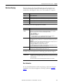
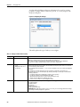
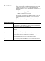
Additional Resources
These resources contain information about related products from Rockwell
Automation.
You can view or download publications at
http://www.rockwellautomation.com/literature/. To order paper copies of technical
documentation, contact your local Allen-Bradley distributor or
Rockwell Automation sales representative.
Resource Description
CompactLogix Controllers Specifications Technical Data,
publication 1769-TD005
Provides CompactLogix controller specifications for all CompactLogix controllers.
1769-SDN DeviceNet Scanner Module User Manual, publication 1769-UM009
Describes how to use the 1769-SDN to back up your CompactLogix 5370 L2 or L3 controller.
Compact High-speed Counter Module User Manual, publication 1769-UM006
Describes high-speed counter operation for standalone 1769-HSC when used with L2 and L3
Compact controllers as well as embedded high-speed counters in L2 embedded controllers.
Compact I/O DeviceNet Scanner Module Installation Instructions,
publication 1769-IN060
Describes how to install the Compact I/O™ modules.
Compact I/O Expansion Power Supplies Installation Instructions, publication
1769-IN028
Describes how to wire the 1769 Compact I/O power supply.
CompactLogix 5370 L1 Controllers Quick Start, publication IASIMP-QS024
Describes basic tasks to design, install and start a CompactLogix 5370 L1 control system.
CompactLogix 5370 L2 Controllers Quick Start, publication IASIMP-QS025 Describes basic tasks to design, install and start a CompactLogix 5370 L2 control system.
CompactLogix 5370 L3 Controllers Quick Start, publication IASIMP-QS023 Describes basic tasks to design, install and start a CompactLogix 5370 L3 control system.
Ethernet Design Considerations Reference Manual, publication ENET-RM002
Describes the following concepts that you must consider when designing a control system that
includes an EtherNet/IP network:
• EtherNet/IP overview
• Ethernet infrastructure
• EtherNet/IP protocol
EtherNet/IP Embedded Switch Technology Application Guide,
publication ENET-AP005
Describes how to use a DLR network topology.
Execution Time and Memory Use for Logix5000 Controller Instructions
Reference Manual, publication 1756-RM087
Assists in estimating the memory use and execution time of programmed logic and in selecting
among different programming options.
Integrated Motion on the EtherNet/IP Network Configuration and Startup User
Manual, publication MOTION-UM003
Describes how to configure an Integrated Motion over
EtherNet/IP motion application and to start up that motion solution in a Logix5000 control system.
POINT I/O 24V dc Expansion Power Supply Installation Instructions,
publication 1734-IN058
Describes the 1734-EP24DC expansion power supply.
POINT I/O Digital and Analog Modules and POINTBlock I/O Modules User
Manual, publication 1734-UM001
Describes how to return a 1734 POINT I/O module to Autobaud.
POINT I/O Field Potential Distributor Modules Installation Instructions,
publication 1734-IN059
Describes the 1734-FPD POINT I/O Field Power Distributor module.
Industrial Automation Wiring and Grounding Guidelines, publication 1770-4.1
Provides general guidelines for installing a Rockwell Automation industrial system.
Product Certifications website, http://www.ab.com Provides declarations of conformity, certificates, and other certification details.

Rockwell Automation Publication 1769-UM021G-EN-P - October 2015 13
Chapter 1
Install the CompactLogix 5370 L1 Controller
Topic Page
Before You Begin 16
Install the Secure Digital Card 19
Install the System 21
Connect to the Controller via a USB Cable 31
Connect the Controller to an EtherNet/IP Network 32
ATTENTION: Environment and Enclosure
This equipment is intended for use in a Pollution Degree 2 industrial environment, in overvoltage Category II applications (as defined
in IEC 60664-1), at altitudes up to 2000 m (6562 ft) without derating.
This equipment is considered Group 1, Class A industrial equipment according to IEC/CISPR 11. Without appropriate precautions,
there may be difficulties with electromagnetic compatibility in residential and other environments due to conducted and radiated
disturbances.
This equipment is supplied as open-type equipment. It must be mounted within an enclosure that is suitably designed for those
specific environmental conditions that will be present and appropriately designed to prevent personal injury resulting from
accessibility to live parts. The enclosure must have suitable flame-retardant properties to prevent or minimize the spread of flame,
complying with a flame spread rating of 5VA, V2, V1, V0 (or equivalent) if nonmetallic. The interior of the enclosure must be
accessible only by the use of a tool. Subsequent sections of this publication may contain additional information regarding specific
enclosure type ratings that are required to comply with certain product safety certifications.
In addition to this publication, see the following:
• Industrial Automation Wiring and Grounding Guidelines, publication 1770-4.1
, for additional installation requirements
• NEMA 250 and IEC 60529, as applicable, for explanations of the degrees of protection provided by enclosures

14 Rockwell Automation Publication 1769-UM021G-EN-P - October 2015
Chapter 1 Install the CompactLogix 5370 L1 Controller
North American Hazardous Location Approval
The following information applies when operating this equipment in
hazardous locations.
Informations sur l’utilisation de cet équipement en environnements
dangereux.
Products marked "CL I, DIV 2, GP A, B, C, D" are suitable for use in Class
I Division 2 Groups A, B, C, D, Hazardous Locations and nonhazardous
locations only. Each product is supplied with markings on the rating
nameplate indicating the hazardous location temperature code.
When combining products within a system, the most adverse
temperature code (lowest "T" number) may be used to help
determine the overall temperature code of the system. Combinations
of equipment in your system are subject to investigation by the local
Authority Having Jurisdiction at the time of installation.
Les produits marqués "CL I, DIV 2, GP A, B, C, D" ne conviennent qu'à
une utilisation en environnements de Classe I Division 2 Groupes A, B,
C, D dangereux et non dangereux. Chaque produit est livré avec des
marquages sur sa plaque d'identification qui indiquent le code de
température pour les environnements dangereux. Lorsque plusieurs
produits sont combinés dans un système, le code de température le
plus défavorable (code de température le plus faible) peut être utilisé
pour déterminer le code de température global du système. Les
combinaisons d'équipements dans le système sont sujettes à
inspection par les autorités locales qualifiées au moment de
l'installation.
WARNING: EXPLOSION HAZARD -
• Do not disconnect equipment unless power has
been removed or the area is known to be
nonhazardous.
• Do not disconnect connections to this equipment
unless power has been removed or the area is
known to be nonhazardous. Secure any external
connections that mate to this equipment by using
screws, sliding latches, threaded connectors, or
other means provided with this product.
• Substitution of components may impair suitability
for Class I, Division 2.
• If this product contains batteries, they must only
be changed in an area known to be nonhazardous.
AVERTISSEMENT: RISQUE D’EXPLOSION –
• Couper le courant ou s'assurer que
l'environnement est classé non dangereux avant
de débrancher l'équipement.
• Couper le courant ou s'assurer que
l'environnement est classé non dangereux avant
de débrancher les connecteurs. Fixer tous les
connecteurs externes reliés à cet équipement à
l'aide de vis, loquets coulissants, connecteurs
filetés ou autres moyens fournis avec ce produit.
• La substitution de composants peut rendre cet
équipement inadapté à une utilisation en
environnement de Classe I, Division 2.
• S'assurer que l'environnement est classé non
dangereux avant de changer les piles.

Rockwell Automation Publication 1769-UM021G-EN-P - October 2015 15
Install the CompactLogix 5370 L1 Controller Chapter 1
European Hazardous Location Approval
The following applies when the product bears the Ex Marking.
This equipment is intended for use in potentially explosive atmospheres as defined by European Union Directive 94/9/EC and has been found to
comply with the Essential Health and Safety Requirements relating to the design and construction of Category 3 equipment intended for use in
Zone 2 potentially explosive atmospheres, given in Annex II to this Directive.
Compliance with the Essential Health and Safety Requirements has been assured by compliance with EN 60079-15 and EN 60079-0.
ATTENTION: This equipment is not resistant to sunlight or other sources of UV radiation.
WARNING:
• This equipment must be installed in an enclosure providing at least IP54 protection when applied in Zone 2 environments.
• This equipment shall be used within its specified ratings defined by Rockwell Automation.
• Provision shall be made to prevent the rated voltage from being exceeded by transient disturbances of more than 40% when
applied in Zone 2 environments.
• Secure any external connections that mate to this equipment by using screws, sliding latches, threaded connectors, or other
means provided with this product.
• Do not disconnect equipment unless power has been removed or the area is known to be nonhazardous.
• Enclosure must be marked with the following: "Warning - Do not open when energized." After installation of equipment into
the enclosure, access to termination compartments shall be dimensioned so that conductors can be readily connected.
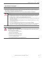
ATTENTION: Prevent Electrostatic Discharge
This equipment is sensitive to electrostatic discharge, which can cause internal damage and affect normal operation. Follow these
guidelines when you handle this equipment:
• Touch a grounded object to discharge potential static.
• Wear an approved grounding wriststrap.
• Do not touch connectors or pins on component boards.
• Do not touch circuit components inside the equipment.
• Use a static-safe workstation, if available.
• Store the equipment in appropriate static-safe packaging when not in use.

16 Rockwell Automation Publication 1769-UM021G-EN-P - October 2015
Chapter 1 Install the CompactLogix 5370 L1 Controller
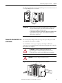
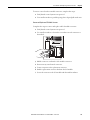
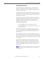
Before You Begin
The CompactLogix™ 5370 L1, series B, controller redesign occurred to provide
an option to use one external power supply for system power and field side power.
There are differences between the CompactLogix 5370 L1, series A and B,
controllers, which are detailed throughout the sections of this manual.
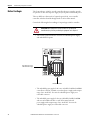
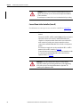
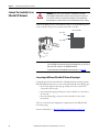
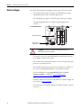
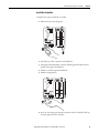
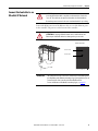
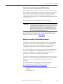
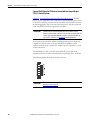
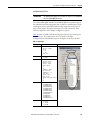
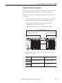
Consider the following before installing a CompactLogix 5370 L1 controller:
• The control system includes the controller, an embedded power supply,
and embedded I/O points.
• The embedded power supply for the series A L16ER, L18ER or L18ERM
controller is a 24V DC nominal, non-isolated power supply with an input
range of 10…28.8V DC. You wire the embedded power supply via a
removable connector.
• The embedded power supply for the series B L16ER, L18ER, L18ERM
and series A L19ER controller is a 24V DC nominal, isolated
power supply with an input range of 10…28.8V DC. You wire the
embedded power supply via a removable connector.
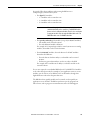
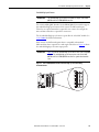
ATTENTION: If this equipment is used in a manner not specified by the
manufacturer, the protection provided by the equipment can be impaired.
Removable Connector for
Embedded Power Supply
Embedded I/O Module

Rockwell Automation Publication 1769-UM021G-EN-P - October 2015 17
Install the CompactLogix 5370 L1 Controller Chapter 1
• A second, fused external power supply must be used to provide power to
other components for only series A L16ER, L18ER, and L18ERM
controllers (see Appendix
C).
• Power for other components can be provided from the external power
supply that is used to provide power to the system for only series B L16ER,
L18ER, L18ERM Controllers, and series A L19ER Controllers.
• The controller has 16 embedded digital input points and 16 embedded
digital output points. You wire the input and output points via a removable
connector.
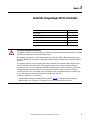
• The controller supports the use of a limited number of
1734 POINT I/O
modules on the POINTBus backplane as local
expansion modules.
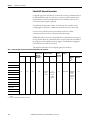
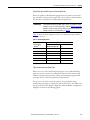
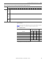
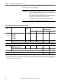
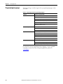
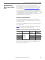
The following table lists local expansion module support by controller
catalog number.
See Chapter 7
for further information about the I/O modules.
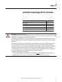
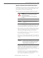
IMPORTANT
You must use a dedicated external Class 2/SELV-approved power
supply to provide power to the system, according to needs of the
application, and within the operating voltage range of the controller
for only series A L16ER, L18ER, and L18ERM controllers.
The external power supply that provides power to the embedded
power supply of the controller cannot be used to provide power to any
other components or devices in the application for only series A L16ER,
L18ER, and L18ERM controllers.
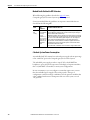
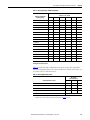
IMPORTANT
You must use the latest series and firmware revision for all 1734
POINT I/O™ modules in the local expansion slots to make sure that your
application operates as expected. Use of an older firmware revision
renders the entire 1734 bus inoperable.
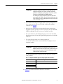
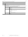
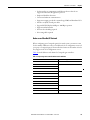
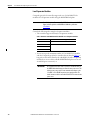
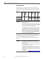
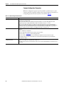
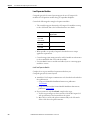
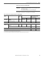
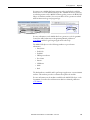
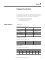
Table 1 - Local Expansion Module Support for CompactLogix 5370 L1 Controllers
Cat. No. 1734 POINT I/O Modules Supported, max
1769-L16ER-BB1B 6
1769-L18ER-BB1B 8
1769-L18ERM-BB1B
1769-L19ER-BB1B

18 Rockwell Automation Publication 1769-UM021G-EN-P - October 2015
Chapter 1 Install the CompactLogix 5370 L1 Controller
1734 POINT I/O modules support removal and insertion under power.
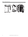
CompactLogix 5370 L1 Controller Parts
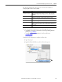
These parts are included in the box when you order your controller:
• Controller - Specific catalog number varies by order
• 1784-SD1 Secure Digital (SD) card with 1 GB of memory storage
A 1784-SD2 SD card with 2 GB of memory storage, or more 1784-SD1
SD cards, are also available if you need extra memory.
• An end cap protective cover that slides onto the right side of the
CompactLogix 5370 L1 control system.
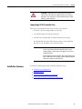
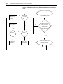
Installation Summary
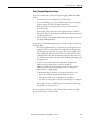
To install a CompactLogix 5370 L1 controller, follow these steps.
1. Install the Secure Digital Card
.
2. Install the System
.
3. Connect to the Controller via a USB Cable
.
4. Connect the Controller to an EtherNet/IP Network
.
ATTENTION: Do not discard the end cap. Use this end cap to cover the
exposed interconnections on the last mounting base on the DIN rail.
Failure to do so could result in equipment damage or injury from
electric shock.
For more information on how to terminate the end of your system, see
page 25
.
IMPORTANT
The life expectancy of nonvolatile media is dependent on the number
of write cycles that are performed. Nonvolatile media use a wear
leveling technique or technology for prolonging the service life, but
avoid frequent writes.
Avoid frequent writes when logging data. We recommend that you log
data to a buffer in the memory of your controller and limit the number
of times data is written to removable media.

Rockwell Automation Publication 1769-UM021G-EN-P - October 2015 19
Install the CompactLogix 5370 L1 Controller Chapter 1
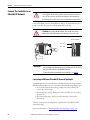
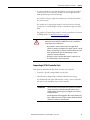
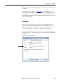
Install the Secure
Digital Card
The CompactLogix 5370 L1 controller is shipped from the factory with the
1784-SD1 SD card installed.
Complete these steps to reinstall an SD card that has been removed from the
controller back into the controller or to install a new SD card into the controller.
We recommend that you leave the SD card in the controller, even when it is not
used. If the controller experiences a major non-recoverable fault, extended fault
information is saved to the card.
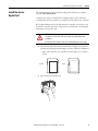
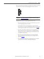
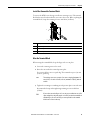
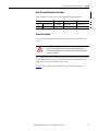
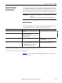
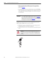
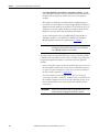
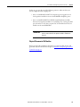
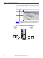
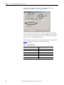
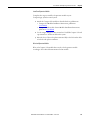
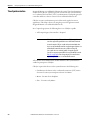
1. Verify that the SD card is locked or unlocked according to your preference.
Consider the following when deciding to lock the card before installation:
– If the card is unlocked, the controller can write data to it or read data
from it.
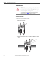
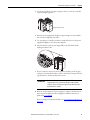
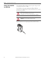
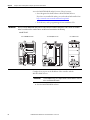
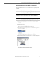
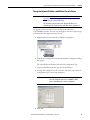
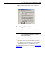
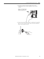
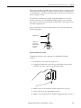
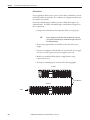
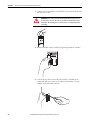
2. Open the door for the SD card.
WARNING: When you insert or remove the SD card while power is on, an
electrical arc can occur. This could cause an explosion in hazardous location
installations.
Be sure that power is removed or the area is nonhazardous before proceeding.
Unlocked Locked

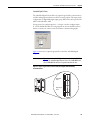
20 Rockwell Automation Publication 1769-UM021G-EN-P - October 2015
Chapter 1 Install the CompactLogix 5370 L1 Controller
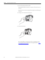
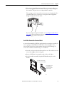
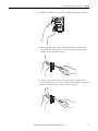
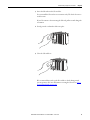
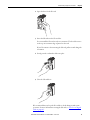
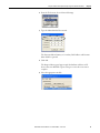
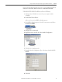
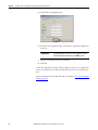
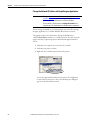
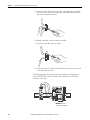
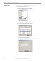
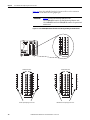
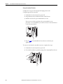
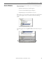
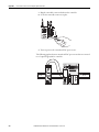
3. Insert the SD card into the SD card slot.
You can install the SD card in only one orientation. The beveled corner is
at the top.
If you feel resistance when inserting the SD card, pull it out and change the
orientation.
4. Gently press the card until it clicks into place.
5. Close the SD card door.
We recommend that you keep the SD card door closed during normal
system operation. For more information on using the SD card, see Use a
Secure Digital Card on page 297.

Rockwell Automation Publication 1769-UM021G-EN-P - October 2015 21
Install the CompactLogix 5370 L1 Controller Chapter 1
Install the System
Complete the following steps to install the CompactLogix 5370 L1
control system.
• Mount the System
• Ground the System
• Install the Controller
• Connect Power to the Controller (Series B) L16 ER, L18ER, L18ERM
series B controllers, and series A L19ER
Mount the System
You mount a CompactLogix 5370 L1 control system on a DIN rail. Before you
complete the steps that are required to install the system, install a DIN rail.
Before you mount a CompactLogix 5370 L1 control system, consider
the following requirements:
• Available DIN Rails
• Minimum Spacing
• System Dimensions
Available DIN Rails
You can mount the CompactLogix 5370 L1 controller on the following
DIN rails:
• EN 50 022 - 35 x 7.5 mm (1.38 x 0.30 in.)
• EN 50 022 - 35 x 15 mm (1.38 x 0.59 in.)
WARNING: When used in a Class I, Division 2, hazardous location, this
equipment must be mounted in a suitable enclosure with proper wiring
method that complies with the governing electrical codes.
ATTENTION: This product is grounded through the DIN rail to chassis ground.
Use zinc-plated yellow-chromate steel DIN rail to assure proper grounding.
The use of other DIN rail materials (for example, aluminum or plastic) that
can corrode, oxidize, or are poor conductors, can result in improper or
intermittent grounding. Secure DIN rail to mounting surface approximately
every 200 mm (7.8 in.) and use end-anchors appropriately.

22 Rockwell Automation Publication 1769-UM021G-EN-P - October 2015
Chapter 1 Install the CompactLogix 5370 L1 Controller
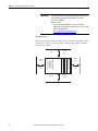
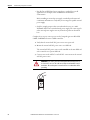
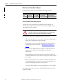
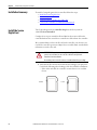
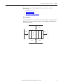
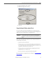
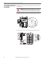
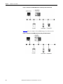
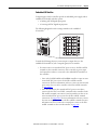
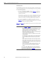
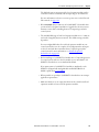
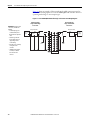
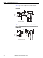
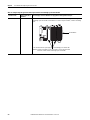
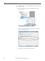
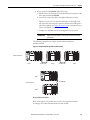
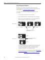
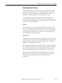
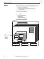
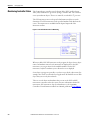
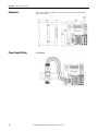
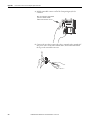
Minimum Spacing
Maintain spacing from enclosure walls, wireways, and adjacent equipment. Allow
50 mm (2 in.) of space on all sides, as shown. This spacing provides ventilation
and electrical isolation.
IMPORTANT
You must install bumpers on the back of your CompactLogix 5370 L1
controller before mounting it on the EN 50022 - 35 x 15 mm
(1.38 x 0.59 in.) DIN rail.
Bumper Selection:
• For more information on Bumper Selection, see Rockwell
Automation® Knowledgebase article #591565. You can access the
article at: (Login required)
https://rockwellautomation.custhelp.com/
Bottom
Top
CompactLogix 5370 L1
Controller with
Embedded Power
Supply and I/O Module
End Cap
50 mm
(2 in.)
50 mm
(2 in.)
50 mm
(2 in.)
50 mm
(2 in.)
Side Side
1734 POINT I/O Module
1734 POINT I/O Module
1734 POINT I/O Module

Rockwell Automation Publication 1769-UM021G-EN-P - October 2015 23
Install the CompactLogix 5370 L1 Controller Chapter 1
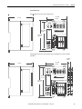
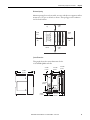
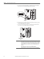
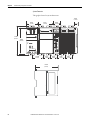
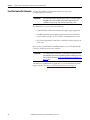
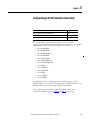
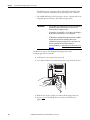
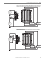
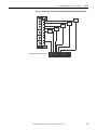
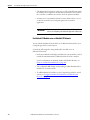
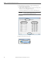
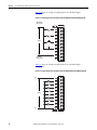
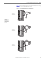
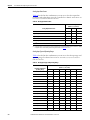
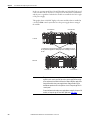
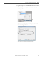
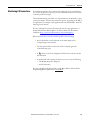
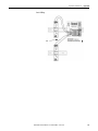
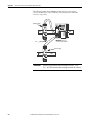
System Dimensions
This graphic shows the system dimensions.
This graphic shows the system dimensions with Expansion I/O modules
installed.
144.00 mm
(5.67 in.)
130.00 mm
(5.11 in.)
100.00 mm
(3.94 in.)
105 mm
(4.13 in.)
144.00 mm
(5.67 in.)
130.00 mm
(5.11 in.)
100.00 mm
(3.94 in.)
12.00 mm
(0.47 in.)
105 mm
(4.13 in.)
Page is loading ...
Page is loading ...
Page is loading ...
Page is loading ...
Page is loading ...
Page is loading ...
Page is loading ...
Page is loading ...
Page is loading ...
Page is loading ...
Page is loading ...
Page is loading ...
Page is loading ...
Page is loading ...
Page is loading ...
Page is loading ...
Page is loading ...
Page is loading ...
Page is loading ...
Page is loading ...
Page is loading ...
Page is loading ...
Page is loading ...
Page is loading ...
Page is loading ...
Page is loading ...
Page is loading ...
Page is loading ...
Page is loading ...
Page is loading ...
Page is loading ...
Page is loading ...
Page is loading ...
Page is loading ...
Page is loading ...
Page is loading ...
Page is loading ...
Page is loading ...
Page is loading ...
Page is loading ...
Page is loading ...
Page is loading ...
Page is loading ...
Page is loading ...
Page is loading ...
Page is loading ...
Page is loading ...
Page is loading ...
Page is loading ...
Page is loading ...
Page is loading ...
Page is loading ...
Page is loading ...
Page is loading ...
Page is loading ...
Page is loading ...
Page is loading ...
Page is loading ...
Page is loading ...
Page is loading ...
Page is loading ...
Page is loading ...
Page is loading ...
Page is loading ...
Page is loading ...
Page is loading ...
Page is loading ...
Page is loading ...
Page is loading ...
Page is loading ...
Page is loading ...
Page is loading ...
Page is loading ...
Page is loading ...
Page is loading ...
Page is loading ...
Page is loading ...
Page is loading ...
Page is loading ...
Page is loading ...
Page is loading ...
Page is loading ...
Page is loading ...
Page is loading ...
Page is loading ...
Page is loading ...
Page is loading ...
Page is loading ...
Page is loading ...
Page is loading ...
Page is loading ...
Page is loading ...
Page is loading ...
Page is loading ...
Page is loading ...
Page is loading ...
Page is loading ...
Page is loading ...
Page is loading ...
Page is loading ...
Page is loading ...
Page is loading ...
Page is loading ...
Page is loading ...
Page is loading ...
Page is loading ...
Page is loading ...
Page is loading ...
Page is loading ...
Page is loading ...
Page is loading ...
Page is loading ...
Page is loading ...
Page is loading ...
Page is loading ...
Page is loading ...
Page is loading ...
Page is loading ...
Page is loading ...
Page is loading ...
Page is loading ...
Page is loading ...
Page is loading ...
Page is loading ...
Page is loading ...
Page is loading ...
Page is loading ...
Page is loading ...
Page is loading ...
Page is loading ...
Page is loading ...
Page is loading ...
Page is loading ...
Page is loading ...
Page is loading ...
Page is loading ...
Page is loading ...
Page is loading ...
Page is loading ...
Page is loading ...
Page is loading ...
Page is loading ...
Page is loading ...
Page is loading ...
Page is loading ...
Page is loading ...
Page is loading ...
Page is loading ...
Page is loading ...
Page is loading ...
Page is loading ...
Page is loading ...
Page is loading ...
Page is loading ...
Page is loading ...
Page is loading ...
Page is loading ...
Page is loading ...
Page is loading ...
Page is loading ...
Page is loading ...
Page is loading ...
Page is loading ...
Page is loading ...
Page is loading ...
Page is loading ...
Page is loading ...
Page is loading ...
Page is loading ...
Page is loading ...
Page is loading ...
Page is loading ...
Page is loading ...
Page is loading ...
Page is loading ...
Page is loading ...
Page is loading ...
Page is loading ...
Page is loading ...
Page is loading ...
Page is loading ...
Page is loading ...
Page is loading ...
Page is loading ...
Page is loading ...
Page is loading ...
Page is loading ...
Page is loading ...
Page is loading ...
Page is loading ...
Page is loading ...
Page is loading ...
Page is loading ...
Page is loading ...
Page is loading ...
Page is loading ...
Page is loading ...
Page is loading ...
Page is loading ...
Page is loading ...
Page is loading ...
Page is loading ...
Page is loading ...
Page is loading ...
Page is loading ...
Page is loading ...
Page is loading ...
Page is loading ...
Page is loading ...
Page is loading ...
Page is loading ...
Page is loading ...
Page is loading ...
Page is loading ...
Page is loading ...
Page is loading ...
Page is loading ...
Page is loading ...
Page is loading ...
Page is loading ...
Page is loading ...
Page is loading ...
Page is loading ...
Page is loading ...
Page is loading ...
Page is loading ...
Page is loading ...
Page is loading ...
Page is loading ...
Page is loading ...
Page is loading ...
Page is loading ...
Page is loading ...
Page is loading ...
Page is loading ...
Page is loading ...
Page is loading ...
Page is loading ...
Page is loading ...
Page is loading ...
Page is loading ...
Page is loading ...
Page is loading ...
Page is loading ...
Page is loading ...
Page is loading ...
Page is loading ...
Page is loading ...
Page is loading ...
Page is loading ...
Page is loading ...
Page is loading ...
Page is loading ...
Page is loading ...
Page is loading ...
Page is loading ...
Page is loading ...
Page is loading ...
Page is loading ...
Page is loading ...
Page is loading ...
Page is loading ...
Page is loading ...
Page is loading ...
Page is loading ...
Page is loading ...
Page is loading ...
Page is loading ...
Page is loading ...
Page is loading ...
Page is loading ...
Page is loading ...
Page is loading ...
Page is loading ...
Page is loading ...
Page is loading ...
Page is loading ...
Page is loading ...
Page is loading ...
Page is loading ...
Page is loading ...
Page is loading ...
Page is loading ...
Page is loading ...
Page is loading ...
Page is loading ...
Page is loading ...
Page is loading ...
Page is loading ...
Page is loading ...
Page is loading ...
Page is loading ...
Page is loading ...
Page is loading ...
Page is loading ...
Page is loading ...
Page is loading ...
Page is loading ...
Page is loading ...
Page is loading ...
Page is loading ...
Page is loading ...
Page is loading ...
Page is loading ...
Page is loading ...
Page is loading ...
Page is loading ...
-
 1
1
-
 2
2
-
 3
3
-
 4
4
-
 5
5
-
 6
6
-
 7
7
-
 8
8
-
 9
9
-
 10
10
-
 11
11
-
 12
12
-
 13
13
-
 14
14
-
 15
15
-
 16
16
-
 17
17
-
 18
18
-
 19
19
-
 20
20
-
 21
21
-
 22
22
-
 23
23
-
 24
24
-
 25
25
-
 26
26
-
 27
27
-
 28
28
-
 29
29
-
 30
30
-
 31
31
-
 32
32
-
 33
33
-
 34
34
-
 35
35
-
 36
36
-
 37
37
-
 38
38
-
 39
39
-
 40
40
-
 41
41
-
 42
42
-
 43
43
-
 44
44
-
 45
45
-
 46
46
-
 47
47
-
 48
48
-
 49
49
-
 50
50
-
 51
51
-
 52
52
-
 53
53
-
 54
54
-
 55
55
-
 56
56
-
 57
57
-
 58
58
-
 59
59
-
 60
60
-
 61
61
-
 62
62
-
 63
63
-
 64
64
-
 65
65
-
 66
66
-
 67
67
-
 68
68
-
 69
69
-
 70
70
-
 71
71
-
 72
72
-
 73
73
-
 74
74
-
 75
75
-
 76
76
-
 77
77
-
 78
78
-
 79
79
-
 80
80
-
 81
81
-
 82
82
-
 83
83
-
 84
84
-
 85
85
-
 86
86
-
 87
87
-
 88
88
-
 89
89
-
 90
90
-
 91
91
-
 92
92
-
 93
93
-
 94
94
-
 95
95
-
 96
96
-
 97
97
-
 98
98
-
 99
99
-
 100
100
-
 101
101
-
 102
102
-
 103
103
-
 104
104
-
 105
105
-
 106
106
-
 107
107
-
 108
108
-
 109
109
-
 110
110
-
 111
111
-
 112
112
-
 113
113
-
 114
114
-
 115
115
-
 116
116
-
 117
117
-
 118
118
-
 119
119
-
 120
120
-
 121
121
-
 122
122
-
 123
123
-
 124
124
-
 125
125
-
 126
126
-
 127
127
-
 128
128
-
 129
129
-
 130
130
-
 131
131
-
 132
132
-
 133
133
-
 134
134
-
 135
135
-
 136
136
-
 137
137
-
 138
138
-
 139
139
-
 140
140
-
 141
141
-
 142
142
-
 143
143
-
 144
144
-
 145
145
-
 146
146
-
 147
147
-
 148
148
-
 149
149
-
 150
150
-
 151
151
-
 152
152
-
 153
153
-
 154
154
-
 155
155
-
 156
156
-
 157
157
-
 158
158
-
 159
159
-
 160
160
-
 161
161
-
 162
162
-
 163
163
-
 164
164
-
 165
165
-
 166
166
-
 167
167
-
 168
168
-
 169
169
-
 170
170
-
 171
171
-
 172
172
-
 173
173
-
 174
174
-
 175
175
-
 176
176
-
 177
177
-
 178
178
-
 179
179
-
 180
180
-
 181
181
-
 182
182
-
 183
183
-
 184
184
-
 185
185
-
 186
186
-
 187
187
-
 188
188
-
 189
189
-
 190
190
-
 191
191
-
 192
192
-
 193
193
-
 194
194
-
 195
195
-
 196
196
-
 197
197
-
 198
198
-
 199
199
-
 200
200
-
 201
201
-
 202
202
-
 203
203
-
 204
204
-
 205
205
-
 206
206
-
 207
207
-
 208
208
-
 209
209
-
 210
210
-
 211
211
-
 212
212
-
 213
213
-
 214
214
-
 215
215
-
 216
216
-
 217
217
-
 218
218
-
 219
219
-
 220
220
-
 221
221
-
 222
222
-
 223
223
-
 224
224
-
 225
225
-
 226
226
-
 227
227
-
 228
228
-
 229
229
-
 230
230
-
 231
231
-
 232
232
-
 233
233
-
 234
234
-
 235
235
-
 236
236
-
 237
237
-
 238
238
-
 239
239
-
 240
240
-
 241
241
-
 242
242
-
 243
243
-
 244
244
-
 245
245
-
 246
246
-
 247
247
-
 248
248
-
 249
249
-
 250
250
-
 251
251
-
 252
252
-
 253
253
-
 254
254
-
 255
255
-
 256
256
-
 257
257
-
 258
258
-
 259
259
-
 260
260
-
 261
261
-
 262
262
-
 263
263
-
 264
264
-
 265
265
-
 266
266
-
 267
267
-
 268
268
-
 269
269
-
 270
270
-
 271
271
-
 272
272
-
 273
273
-
 274
274
-
 275
275
-
 276
276
-
 277
277
-
 278
278
-
 279
279
-
 280
280
-
 281
281
-
 282
282
-
 283
283
-
 284
284
-
 285
285
-
 286
286
-
 287
287
-
 288
288
-
 289
289
-
 290
290
-
 291
291
-
 292
292
-
 293
293
-
 294
294
-
 295
295
-
 296
296
-
 297
297
-
 298
298
-
 299
299
-
 300
300
-
 301
301
-
 302
302
-
 303
303
-
 304
304
-
 305
305
-
 306
306
-
 307
307
-
 308
308
-
 309
309
-
 310
310
-
 311
311
-
 312
312
-
 313
313
-
 314
314
-
 315
315
-
 316
316
-
 317
317
-
 318
318
-
 319
319
-
 320
320
-
 321
321
-
 322
322
-
 323
323
-
 324
324
-
 325
325
-
 326
326
-
 327
327


Allen-Bradley 1769-L18ERM-BB1B User manual
- Category
- Networking
- Type
- User manual
Ask a question and I''ll find the answer in the document
Finding information in a document is now easier with AI
Related papers
-
Allen-Bradley Kinetix 350 Reference guide
-
Allen-Bradley 1756 ControlLogix Reference guide
-
Allen-Bradley 1769-HSC Installation Instructions Manual
-
-
-
-
-
-
-
Other documents
-
Sitecom SMLN-218 OEM Datasheet
-
 Rockwell Automation Allen-Bradley CompactLogix 5370 L2 Series Product information
-
Rockwell Automation 1769-PA2 Specification
-
 Rockwell Automation 40072-107-01 Installation Instructions Manual
-
Rockwell Automation Allen-Bradley 5069 Compact GuardLogix Programming Manual
-
 Rockwell Automation Allen-Bradley 1756-EN2TSC Installation Instructions Manual
-
 Rockwell Automation Allen-Bradley 1769-IQ32T Installation Instructions Manual
-
Rockwell Automation Allen-Bradley Logix5000 Quick start guide
-
 Rockwell Automation 1734-OE4C Installation Instructions Manual
-
 Rockwell Automation DEVICENET 1771-SDN User manual


