Page is loading ...

IO-Link for Solid-state Pressure Switches
Catalog Number 836P-Dx
User Manual
Original Instructions

Important User Information
Read this document and the documents listed in the additional resources section about installation, configuration, and
operation of this equipment before you install, configure, operate, or maintain this product. Users are required to
familiarize themselves with installation and wiring instructions in addition to requirements of all applicable codes, laws,
and standards.
Activities including installation, adjustments, putting into service, use, assembly, disassembly, and maintenance are
required to be carried out by suitably trained personnel in accordance with applicable code of practice.
If this equipment is used in a manner not specified by the manufacturer, the protection provided by the equipment may
be impaired.
In no event will Rockwell Automation, Inc. be responsible or liable for indirect or consequential damages resulting from
the use or application of this equipment.
The examples and diagrams in this manual are included solely for illustrative purposes. Because of the many variables and
requirements associated with any particular installation, Rockwell Automation, Inc. cannot assume responsibility or
liability for actual use based on the examples and diagrams.
No patent liability is assumed by Rockwell Automation, Inc. with respect to use of information, circuits, equipment, or
software described in this manual.
Reproduction of the contents of this manual, in whole or in part, without written permission of Rockwell Automation,
Inc., is prohibited
Throughout this manual, when necessary, we use notes to make you aware of safety considerations.
Labels may also be on or inside the equipment to provide specific precautions.
WARNING: Identifies information about practices or circumstances that can cause an explosion in a hazardous
environment, which may lead to personal injury or death, property damage, or economic loss.
ATTENTION: Identifies information about practices or circumstances that can lead to personal injury or death, property
damage, or economic loss. Attentions help you identify a hazard, avoid a hazard, and recognize the consequence.
IMPORTANT Identifies information that is critical for successful application and understanding of the product.
SHOCK HAZARD: Labels may be on or inside the equipment, for example, a drive or motor, to alert people that dangerous
voltage may be present.
BURN HAZARD: Labels may be on or inside the equipment, for example, a drive or motor, to alert people that surfaces may
reach dangerous temperatures.
ARC FLASH HAZARD: Labels may be on or inside the equipment, for example, a motor control center, to alert people to
potential Arc Flash. Arc Flash will cause severe injury or death. Wear proper Personal Protective Equipment (PPE). Follow ALL
Regulatory requirements for safe work practices and for Personal Protective Equipment (PPE).

Rockwell Automation Publication IOLINK-UM001A-EN-P - August 2017 3
Table of Contents
Preface
Overview and Benefits . . . . . . . . . . . . . . . . . . . . . . . . . . . . . . . . . . . . . . . . . . 5
Terminology. . . . . . . . . . . . . . . . . . . . . . . . . . . . . . . . . . . . . . . . . . . . . . . . . . . 5
Additional Resources . . . . . . . . . . . . . . . . . . . . . . . . . . . . . . . . . . . . . . . . . . . 6
Chapter 1
836P Pressure Sensor with
IO-Link Overview
What Is IO-Link? . . . . . . . . . . . . . . . . . . . . . . . . . . . . . . . . . . . . . . . . . . . . . . 7
Why IO-Link? . . . . . . . . . . . . . . . . . . . . . . . . . . . . . . . . . . . . . . . . . . . . . . . . . 7
Seamless Integration . . . . . . . . . . . . . . . . . . . . . . . . . . . . . . . . . . . . . . . . 7
Real-time Diagnostics and Trends . . . . . . . . . . . . . . . . . . . . . . . . . . . 8
Sensor Health Status. . . . . . . . . . . . . . . . . . . . . . . . . . . . . . . . . . . . . . . . 8
Device Profiles and Automatic Device Configuration. . . . . . . . . . 8
Descriptive Tags. . . . . . . . . . . . . . . . . . . . . . . . . . . . . . . . . . . . . . . . . . . . 8
How Does IO-Link Work? . . . . . . . . . . . . . . . . . . . . . . . . . . . . . . . . . . . . . 8
Transmission Rates . . . . . . . . . . . . . . . . . . . . . . . . . . . . . . . . . . . . . . . . . 9
Transmission Quality . . . . . . . . . . . . . . . . . . . . . . . . . . . . . . . . . . . . . . . 9
Response Time of the IO-Link System . . . . . . . . . . . . . . . . . . . . . . . 9
IO-Link Data Types. . . . . . . . . . . . . . . . . . . . . . . . . . . . . . . . . . . . . . . . . . . . 9
Process Data . . . . . . . . . . . . . . . . . . . . . . . . . . . . . . . . . . . . . . . . . . . . . . 10
Value Status. . . . . . . . . . . . . . . . . . . . . . . . . . . . . . . . . . . . . . . . . . . . . . . 10
Device Data. . . . . . . . . . . . . . . . . . . . . . . . . . . . . . . . . . . . . . . . . . . . . . . 10
Events . . . . . . . . . . . . . . . . . . . . . . . . . . . . . . . . . . . . . . . . . . . . . . . . . . . . 10
Accessing IO-Link Data . . . . . . . . . . . . . . . . . . . . . . . . . . . . . . . . . . . . . . . 10
Cyclic Data . . . . . . . . . . . . . . . . . . . . . . . . . . . . . . . . . . . . . . . . . . . . . . . 10
Acyclic Data . . . . . . . . . . . . . . . . . . . . . . . . . . . . . . . . . . . . . . . . . . . . . . 10
Start up of the I/O System . . . . . . . . . . . . . . . . . . . . . . . . . . . . . . . . . . . . . 11
Assign Device Parameters . . . . . . . . . . . . . . . . . . . . . . . . . . . . . . . . . . . . . . 11
Premier Integration . . . . . . . . . . . . . . . . . . . . . . . . . . . . . . . . . . . . . . . . . . . 12
836P IO-Link Features . . . . . . . . . . . . . . . . . . . . . . . . . . . . . . . . . . . . . . . . 13
Chapter 2
Set up the 836P Sensor for
IO-Link Mode
Hardware. . . . . . . . . . . . . . . . . . . . . . . . . . . . . . . . . . . . . . . . . . . . . . . . . . . . . 15
Software. . . . . . . . . . . . . . . . . . . . . . . . . . . . . . . . . . . . . . . . . . . . . . . . . . . . . . 15
Example: Set up the Hardware . . . . . . . . . . . . . . . . . . . . . . . . . . . . . . . . . 16
Chapter 3
Create a Project Begin a New Project . . . . . . . . . . . . . . . . . . . . . . . . . . . . . . . . . . . . . . . . . . . 19
AOP Installation. . . . . . . . . . . . . . . . . . . . . . . . . . . . . . . . . . . . . . . . . . . . . . 21
Chapter 4
Configure the IO-Link Master Configuration Procedure . . . . . . . . . . . . . . . . . . . . . . . . . . . . . . . . . . . . . . 23

4 Rockwell Automation Publication IOLINK-UM001A-EN-P - August 2017
Table of Contents
Chapter 5
Register the 836P IODD Registration Procedure . . . . . . . . . . . . . . . . . . . . . . . . . . . . . . . . . . . . . . . . 27
Chapter 6
Connect the 836P Sensor to the
IO-Link Master
Connection Procedure. . . . . . . . . . . . . . . . . . . . . . . . . . . . . . . . . . . . . . . . . 31
Appendix A
Install the Add-on Profile Introduction. . . . . . . . . . . . . . . . . . . . . . . . . . . . . . . . . . . . . . . . . . . . . . . . . . 33
Perform the Installation . . . . . . . . . . . . . . . . . . . . . . . . . . . . . . . . . . . . . . . 33
Appendix B
Message Structure and
Configuration Examples
Configure a Message Instruction. . . . . . . . . . . . . . . . . . . . . . . . . . . . . . . . 37
Example Format of a Read Message . . . . . . . . . . . . . . . . . . . . . . . . . 37
Read Data from the Sensor . . . . . . . . . . . . . . . . . . . . . . . . . . . . . . . . . 39
Example Format of a Write Message . . . . . . . . . . . . . . . . . . . . . . . . 39
Validation of Write. . . . . . . . . . . . . . . . . . . . . . . . . . . . . . . . . . . . . . . . 41
Service Code . . . . . . . . . . . . . . . . . . . . . . . . . . . . . . . . . . . . . . . . . . . . . . 42
Source Length: from Data Structure Tables . . . . . . . . . . . . . . . . . . 42
Index . . . . . . . . . . . . . . . . . . . . . . . . . . . . . . . . . . . . . . . . . . . . . . . . . . . . . . . .43

Rockwell Automation Publication IOLINK-UM001A-EN-P - August 2017 5
Preface
This manual is a reference guide for IO-Link for your Bulletin 836P solid-state
pressure switch. It describes the procedures to configure IO-Link and connect
it to your 836P pressure switch. For detailed 836P pressure switch information,
see 836P-UM001
.
Overview and Benefits
Rockwell Automation is the only supplier who provides every piece of the
Connected Enterprise solution. Plus, exclusive features, and Premier
Integration between Allen-Bradley® components and an Integrated
Architecture® system allow for a seamless connection and commission of
control components. These features allow you to reap the benefits of an
IO-Link solution with access to more detailed and customized plant-floor
information than other solutions can offer.
Terminology
The following abbreviations are used throughout this manual. For definitions
of terms that are not listed here, refer to the Allen-Bradley Industrial
Automation Glossary, publication AG-7.1
.
Table 1 - Abbreviations
Abbreviation Definition
ADC Automatic Device Configuration
AOI Add-On Instruction
AOP Add-on Profile
ASN Application Specific Name
IEC International Electrotechnical Commission
IODD I/O Device Description
NEC National Electric Code
QD Quick Disconnect
RGB Red, Green, Blue
SIO Standard I/O
TB Teach Background
TD Teach Dynamic
TM Teach Mark

6 Rockwell Automation Publication IOLINK-UM001A-EN-P - August 2017
Preface
Additional Resources
These documents contain additional information concerning related products
from Rockwell Automation.
You can view or download publications at
http://www.rockwellautomation.com/global/literature-library/overview.page
.
To order paper copies of technical documentation, contact your local
Allen-Bradley distributor or Rockwell Automation sales representative.
Resource Description
Solid-state Pressure Switches User Manual,
publication 836P-UM001
Describes the procedures that are used to install, wire,
and troubleshoot pressure switches.
Industrial Automation Wiring and Grounding Guidelines,
publication 1770-4.1
Provides general guidelines for installing a
Rockwell Automation® industrial system.
Product Certifications website, http://
www.rockwellautomation.com/global/certification/
overview.page
Provides declarations of conformity, certificates, and
other certification details.

Rockwell Automation Publication IOLINK-UM001A-EN-P - August 2017 7
Chapter 1
836P Pressure Sensor with IO-Link Overview
What Is IO-Link?
The IO-Link technology is an open point-to-point communication standard
and was launched as (IS) IEC 61131-9. IO-Link is now the first globally
standardized technology for sensor and actuator communication with a field
bus system. This technology provides benefits to both OEMs and end users.
IO-Link provides communications-capable sensors to the control level by a
cost-effective point-to-point connection. IO-Link provides a point-to-point
link between the I/O module and sensor that is used for transferring detailed
diagnostics, device identity information, process data, and parameterization.
IO-Link communication is based on a master-slave structure in which the
master controls the interface access to the sensor. The option of using the
intelligence that is integrated into the sensor provides you with new methods
to commission your device. Benefits of IO-Link technology range from
reduced installation time during startup to increased diagnostics over the
lifetime of the machine. Other benefits of IO-Link technology include:
• Reduced inventory and operating costs
• Increased uptime/productivity
• Simplified design, installation, creation, and maintenance
• Enhanced flexibility and scalability
• Detailed diagnostic information for preventive maintenance
Why IO-Link?
IO-Link offers a full range of advanced features and functions.
Seamless Integration
• Forward and backward compatible, sensor catalog numbers remain the
same
• No special cables required
• Connectivity options remain the same
• Access IO-Link functionality by simply connecting an IO-Link enabled
device to an IO-Link master
• Analog devices no longer require a dedicated input card

8 Rockwell Automation Publication IOLINK-UM001A-EN-P - August 2017
Chapter 1 836P Pressure Sensor with IO-Link Overview
Real-time Diagnostics and Trends
• Real-time monitoring of the entire machine down to the sensor level
• Optimized preventive maintenance—identify and correct issues before
failures can occur
• Detect sensor malfunctions/failure
Sensor Health Status
• Real-time monitoring verifies that sensors are operating correctly
• Detect damaged sensors and pinpoint their exact location for quick
troubleshooting through Application Specific Name parameter
Device Profiles and Automatic Device Configuration
• “Golden” device configurations are stored in the IO-Link master
module
• Multiple configurations can be stored in controller to support changes
in machine production, for example tool changes
• Within minutes instead of hours, modify sensor parameters to produce
different finished goods
Descriptive Tags
• Faster programming during initial setup
• More efficient troubleshooting process-data tags are named based on the
information they provide
• Easily monitor sensor data though intuitive tag names
How Does IO-Link Work?
IO-Link delivers data over the same standard field cabling used today. By
connecting an IO-Link sensor to an IO-Link master, the field-device data and
diagnostics are accessible. IO-Link allows you to go beyond product detection
on the machine. You can now monitor the health of the machine as it runs.
Pin Signal Remark
1 L+ 24V
2outDepends on sensor
3L- Ground
4 C/Q Communication/
switching signal
IMPORTANT The response time of an IO-Link system may not be fast enough for high-
speed applications. In this case, it is possible to monitor or configure the
sensor through IO-Link on pin 4 of the sensors while connecting pin 2 (if the
sensor offers a second output) of the sensor to a standard input card.

Rockwell Automation Publication IOLINK-UM001A-EN-P - August 2017 9
836P Pressure Sensor with IO-Link Overview Chapter 1
Transmission Rates
Three communication rates are specified for the IO-Link device:
• COM 1 = 4.8 kBd
• COM 2 = 38.4 kBd
• COM 3 = 230.4 kBd
An IO-Link device typically supports only one of the specified transmissions
rates, while the IO-Link V1.1 specifications requires an IO-Link master to
support all three communication rates.
Transmission Quality
The IO-Link communication system operates at a 24V level. If a transmission
fails, the frame is repeated two more times. If the transmission fails on the
second try, the IO-Link master recognizes a communication failure and signals
it to the controller.
Response Time of the IO-Link System
The device description file (IODD) of the device contains a value for the
minimum cycle time of the device. This value indicates the time intervals at
which the master addresses the device. The value has a large influence on the
response time. In addition, the master has an internal processing time that is
included in the calculation of the system response time.
Devices with different minimum cycle times can be configured on one master.
The response time differs so for these devices. When configuring the master,
you can specify a fixed cycle time (minimum of 3 ms) and the device-specific
minimum cycle time that is stored in the IODD. The master then addresses the
device that is based on this specification. The typical response time for a device
therefore results from the effective cycle time of the device and the typical
internal processing time of the master.
IO-Link Data Types
There are four data types available through IO-Link:
Process data → Cyclic data
Value status → Cyclic data
Device data → Acyclic data
Events → Acyclic data

10 Rockwell Automation Publication IOLINK-UM001A-EN-P - August 2017
Chapter 1 836P Pressure Sensor with IO-Link Overview
Process Data
The process data of the devices are transmitted cyclically in a data frame in
which the device specifies the size of the process data. Depending on the
device, 0…32 bytes of process data are possible (for each input and output).
The consistency width of the transmission is not fixed and is thus dependent
on the master.
Some devices can support multiple process data modes, which allows for
selection of different cyclic process data themes.
Value Status
The value status indicates whether the process data is valid or invalid. The
value status can be transmitted cyclically with the process data.
Device Data
Device data supports device-specific configurable parameters, identification
data, and diagnostic information. They are exchanged acyclically and at the
request of the IO-Link master. Device data can be written to the device (Write)
and also read from the device (Read).
Events
When an event occurs, the device signals the presence of the event to the
master. The master then reads out the event. Events can be error messages and
warnings/maintenance data. Error messages are transmitted from the device to
the controller via the IO-Link master. The transmission of device parameters
or events occurs independently from the cyclic transmission of process data.
Accessing IO-Link Data
Cyclic Data
To exchange the cyclic process data between an IO-Link device and a
controller, the IO-Link data from the IO-Link master is placed on the address
ranges assigned beforehand. The user program on the controller accesses the
process values using these addresses and processes them. The cyclic data
exchange from the controller to the IO-Link device (for example, IO-Link
sensor) is performed in reverse.
Acyclic Data
Acyclic data, such as device parameters or events, are exchanged using a
specified index and subindex range. The controller accesses these using Explicit
Messaging. The use of the index and subindex ranges allows targeted access to
the device data (for example, for reassigning the device or master parameters
during operation).

Rockwell Automation Publication IOLINK-UM001A-EN-P - August 2017 11
836P Pressure Sensor with IO-Link Overview Chapter 1
Start up of the I/O System
If the port of the master is set to IO-Link mode, the IO-Link master attempts
to communicate with the connected IO-Link device. To do so, the IO-Link
master sends a defined signal (wake up pulse) and waits for the IO-Link device
to reply.
The IO-Link master initially attempts to communicate at the highest defined
data transmission rate. If unsuccessful, the IO-Link master then attempts to
communicate at the next lower data transmission rate.
If the master receives a reply, the communication begins. Next, it exchanges the
communication parameters. If necessary, parameters that are saved in the
system are transmitted to the device. Then, the cyclic exchange of the process
data and value status begins.
Assign Device Parameters
A device that is built for a specific application requires changes to parameter
settings. The device parameters and setting values are contained in the IODD
of the device.
I/O Device Description (IODD) files contain information about the device
identity, parameters, process data, diagnostic data, and communication
properties. These files are required to establish communication with the
sensors via IO-Link.
The IODD consists of multiple data files; the main file and several optional
language files are in XML-format and graphic files are in PNG format
(portable network graphics). These files adhere to the IO-Link open standard,
which means that they can be used with any IO-Link masters.
IODD files are assigned using Studio 5000® and the 1734-4IOL Add-on
Profile (AOP).
(1)
(1) When using the 1734-4IOL IO-Link master module.

12 Rockwell Automation Publication IOLINK-UM001A-EN-P - August 2017
Chapter 1 836P Pressure Sensor with IO-Link Overview
Premier Integration
The Studio 5000 Logix Designer® environment combines design and
engineering elements in one interface, which allows you to access I/O and
configuration data across the Integrated Architecture® system.
Rockwell Automation® solutions, provide a smooth, consistent integration of
IO-Link enabled devices into the system.
To simplify the integration of the Rockwell Automation® IO-Link devices to
the Rockwell Automation architecture, there is an IO-Link AOP available for
the 1734-4IOL master module. The use of an AOP simplifies the setup of
devices by providing the necessary fields in an organized manner. The AOP
allows design and configuration of the system in a quick and efficient manner.
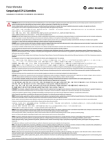
36
Main patchcord 889M-R19RMMU-2
Passive Distribution Box
898D-P54PT-M12
Main patchcord
889M-R11RMMU-2
Four separate colors
Passive Distribution Box
898D-P58PT-M12
up to any 8
(Requires two IO-Link Masters
Sensors
SensorsSensors
42EF 42EF 42EF 871TM 42EF 42EF
836P
871TM
Patchcords (4 pcs.) 889D-F4ACDM-2

Rockwell Automation Publication IOLINK-UM001A-EN-P - August 2017 13
836P Pressure Sensor with IO-Link Overview Chapter 1
836P IO-Link Features
The 836P pressure switch communicates the following parameters via
IO-Link:
• Teach the sensor setpoints is achieved via the AOP through
Studio 5000®
• Pressure in PSI reduces the need to scale the pressure data on the PLC
and saves commissioning time
• Overpressure event informs you if an over pressure condition is detected
• Locking options are available to lock local settings when operating in
IO-Link mode, and therefore changes made by anyone does not change
the settings of the sensor
Process Data Maps allow the selection of the type of information that is
continuously sent to the PLC as a process data parameter.
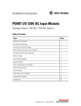
• Automatic Device Configuration (ADC): Replacing damaged sensors
is easy. Simply remove the old Allen-Bradley® sensor and connect the
new one—the controller automatically sends the configuration to the
new sensor.
• Application Specific Name (ASN): When a machine has multiple
sensors with the same catalog number, the ASN parameter makes it easy
to identify the sensor during commissioning and the lifetime of the
machine when collecting data. The name resides in the project and the
sensor itself.
• Tag Na ming for I/ O D a ta : Rockwell Automation system solutions
provide tag names that are based on the Allen-Bradley sensor connected.
I/O data is converted, formatted, and named based on the Allen-Bradley
sensor applied. Reduces commissioning time by the OEM and reduces
your troubleshooting time when searching for sensor data. Consistent
naming techniques are used across multiple product families when
compared to standard I/O data naming techniques.
Allen-Bradley Controller
Allen-Bradley
IO-Link Master
ADC
ADC
Sensor
Configuration
Master
Configuration
42EF

14 Rockwell Automation Publication IOLINK-UM001A-EN-P - August 2017
Chapter 1 836P Pressure Sensor with IO-Link Overview
Notes:

Rockwell Automation Publication IOLINK-UM001A-EN-P - August 2017 15
Chapter 2
Set up the 836P Sensor for IO-Link Mode
This chapter shows the physical hardware and software that is required to
configure the 836P pressure switch through IO-Link and provides a simple
guide to install the hardware.
Hardware
Required:
• 836P solid-state pressure display sensor
• CompactLogix™ or ControlLogix® PLC platform
• POINT I/O™ communications interface: 1734-AENTR
• POINT I/O IO-Link master module: 1734-4IOL
• POINT I/O terminal base: 1734-TB
• RJ45 network cable for EtherNet/IP™ connectivity:
1585J-M8TBJM-1M9*
Optional:
• 889D cordsets: 889D-F4AC-5x (IO-Link maximum acceptable cable
length is 20 m (65.6 ft))
Software
Required:
• Studio 5000® environments, version 20 and higher
• Sensor-specific IODD
• 1734-4IOL IO-Link Add-on Profile (AOP)

16 Rockwell Automation Publication IOLINK-UM001A-EN-P - August 2017
Chapter 2 Set up the 836P Sensor for IO-Link Mode
Example: Set up
the Hardware
In this example, we are showing an Allen-Bradley® POINT I/O chassis with a
1734-AENTR adapter and a 1734-4IOL IO-Link master module in the first
slot. The 1734-AENTR is communicating with a CompactLogix™ controller
via EtherNet/IP.
When adding an 836P pressure switch to the 1734-4IOL master module,
complete the following steps:
1. Provide power to the 1734-AENTR adapter.
2. Set the node address on 1734-AENTR adapter.
3. Connect the 1734-AENTR to the controller with the recommended
RJ45 Ethernet cable.
4. Wire the sensor cable to the desired location on the IO-Link master (in
this example, we are showing the sensor that is wired to the channel 0).
5. Connect the 836P to the other end of the sensor cable.
836P
Patchcords (1 pc.) 889D-F4ACDM-2)

Rockwell Automation Publication IOLINK-UM001A-EN-P - August 2017 17
Set up the 836P Sensor for IO-Link Mode Chapter 2
6. After connecting the sensor, you must create/open a project in Studio
5000 to establish communication with the controller and to add the
1734-AENTR adapter and 1734-4IOL IO-Link master module to
Controller Organizer Tree (see Configure the IO-Link Master on
page 23 and Register the 836P IODD on page 27 for detailed
instructions).
IMPORTANT Once the sensor adapter and the master module have been configured in the
Controller Organizer Tree and the 836P has been wired to the master
module, the green status indicator on the sensor flashes at a 1 Hz rate. This
flash indicates that it is operating in IO-Link mode.

18 Rockwell Automation Publication IOLINK-UM001A-EN-P - August 2017
Chapter 2 Set up the 836P Sensor for IO-Link Mode
Notes:

Rockwell Automation Publication IOLINK-UM001A-EN-P - August 2017 19
Chapter 3
Create a Project
Begin a New Project
To begin a new project in Studio 5000®, use the following procedure.
1. Double-click the Studio 5000 icon.
2. Click New Project.
3. To program the controller, select the controller that is used. In this
example, it is the “1769 L24ER” CompactLogix.
IMPORTANT If there is an existing project within Studio 5000 with CompactLogix™ or
ControlLogix® hardware that is installed and online, go to Configure the IO-
Link Master on page 23.

20 Rockwell Automation Publication IOLINK-UM001A-EN-P - August 2017
Chapter 3 Create a Project
4. After selecting the controller, name the project and click Next. In this
example, the project name is “Project836P.”
5. Once the project opens up, configure the IP address of the controller to
help ensure communication. To configure the IP address, click the
browsing icon.
Project836P
/