Page is loading ...

IMPORTANT SAFEGUARDS
READ AND FOLLOW ALL SAFETY INSTRUCTIONS.
When using electrical equipment, basic safety precautions should always be followed including the following:
• DISCONNECT AC POWER SUPPLY BEFORE SERVICING.
• Installation and servicing of this equipment should be performed by qualified service personnel only.
• Ensure that the electrical wiring conforms to the National Electrical Code NEC® and local regulations, if
applicable.
• Do not mount near gas or electrical heaters.
• Do not use outdoors.
• Do not let power cords touch hot surfaces.
• Equipment should be mounted in locations and at heights where it will not be readily subjected to tampering
by unauthorized personnel.
• The use of accessory equipment not recommended by the manufacturer may cause an unsafe condition.
• Any modification or use of non-original components will void the warranty and product liability.
• Do not use this equipment for other than intended use.
• Allow battery to charge for 24 hours before first use.
• Use caution when servicing batteries. Battery acid can cause burns to skin and eyes. If acid is spilled on skin
or eyes, flush with fresh water and contact a physician immediately.
SAVE THESE INSTRUCTIONS!
Technical Support ■ (623) 580-8943 ■ [email protected]
RSL Series
Installation Instructions
10070255 REV 1 - 02/22 1800-533-3948 www.barronltg.com

Installation
1. Extend unswitched 24 hour AC supply of rated voltage to a junction
box (supplied by others) installed in accordance with all applicable
codes and standards. Leave at least 8 inches of slack wire. This
circuit should NOT be energized/live at this time.
2. Open the unit by unscrewing the cover screws on the sides of the unit
(Figure 2). The front cover can then be lifted up and removed.
3. Unit is supplied with universal spider knockouts and keyhole slots
stamped into the back of the cabinet. Knock out the appropriate
hole(s) and bring wires through the hole(s) into the cabinet.
4. Mount the unit securely into place. Do not rely on the electrical box as
the only support for the unit. There are two keyhole mounting slots
provided in the back of the unit for wall mounting.
5. Make proper wiring connections between the AC supply and the unit’s
transformer per diagram provided (Figure 4). Insulate unused wire!
Connect ground to supplied green ground wire in accordance with
local codes. Reassemble all wire connections and connectors.
CAUTION! - Failure to insulate unused wire may result in a shock
hazard or unsafe condition as well as equipment failure.
6. For line cord connection on 120VAC Supply Only remove the double
“D” knockout from the side of the cabinet. Feed the end of the line
cord through the double “D” hole and press the cord strain relief into
the hole to secure. Connect the line cord leads to the black, white,
and green lead (Figure 4). CAUTION! - Failure to insulate unused
wire may result in a shock hazard or unsafe condition as well as
equipment failure.
7. For large units the batteries may be shipped separately. Install
batteries into the cabinet and complete the appropriate battery
connections (Figure 5).
8. Uncoil the wire lead(s) from the Positive circuit board terminal (+) and
connect to the positive terminal connector on the battery (Figure 3).
9. Route wires and secure in place.
10. Replace cover and secure cover screws.
11. Turn on AC line voltage supply.
12. Position lamps/heads to provide best lighting distribution by loosening
head set screws to adjust angle and swivel. Manually rotate or twist
head to desired position then tighten set screws to lock position.
CAUTION: This equipment is furnished with a sophisticated low voltage
battery dropout circuit to protect the battery from over-discharge after its
useful output has been used. Allow 24 hours recharge time after
installation or power failure for full-load testing.
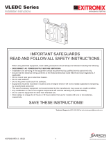
Fig. 1
Fig. 2
Heads/Lamps
Cover
Screw
Test Switch &
LED Indicators
Fig. 3
Uncoil wire
and connect
end to battery
terminal
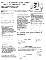
Fig. 4 WHITE - Neutral / Common
BLACK - 120V Line / Hot
RED - 347V Line / Hot
ORANGE - 277V Line / Hot
CHARGER BOARD
STANDARD DUAL INPUT VERSION
LAMPS
BATTERY+
LAMP +
LAMP –
FUSE
BATTERY–
POS
+
NEG
–
BATTERY PCBA
TEST
CHARGE
AC ON
GREEN - Ground
Fig. 5
Black
Black Black
RSL Series
Installation Instructions
10070255 REV 1 - 02/22 2800-533-3948 www.barronltg.com

OPERATION
1. To Test, depress the TEST Switch. Charge indicator will go out and the DC lamps will come on.
2. Release the TEST Switch. DC lamps will be extinguished, and the charge indicator will come on.
3. A bright charge indicator indicates a high charge rate. After the battery has reached full charge, the indicator light will go
out. Under normal operation the high charge indicator will turn off and on intermittently while the unit is in standby mode
(regular/mains AC present) since the charge rate will vary in order to maintain an optimal battery charge.
MAINTENANCE
1. Code requires that the equipment be tested every 30 days for 30 seconds, and that written records be maintained.
Further, the equipment is to be tested once a year for the required duration as per Code. The battery is to be replaced
or the equipment repaired whenever the equipment fails to operate as intended during the duration test. Written records
of test results and any repairs made must be maintained. It is strongly recommended to comply with all Code
requirements.
2. Clean lenses on a regular basis.
NOTE: The servicing of any parts should be performed by qualified service personnel only. The use of replacement parts
not furnished by the manufacturer may cause equipment failure and will void the warranty.
TROUBLESHOOTING
EMERGENCY LAMPS DO NOT COME ON AT ALL
Pilot Light is out before test...
1. Check AC supply - be sure unit has 24 hour AC supply (unswitched).
2. AC supply is OK, and indicator light is out, replace PC Board Assembly.
Pilot Light is on before test...
3. Either the output is shorted or overloaded, or the battery is not connected.
4. Battery is severely discharged. Allow 24 hours for recharge and then retest. NOTE: This could be the result of a
switched AC supply to the unit (which has been turned off at some point), a battery with a shorted cell, an old battery or
a battery which has been discharged due to a long power outage and is not yet fully recharged.
EMERGENCY LAMPS COME ON DIM WHEN TEST BUTTON IS PRESSED
1. Battery discharged - permit unit to charge for 24 hours and then retest. If lamps are still dim, check charger for proper
function. If charger functions correctly, replace battery.
EMERGENCY LAMPS COME ON WHEN BATTERY IS FIRST CONNECTED
1. Battery may be connected in reverse polarity. Check connections. Connect Positive lead to Positive battery terminal
and Negative lead to Negative battery terminal. The lamps should then turn off and the charge indicator should light
when AC power is applied.
EMERGENCY LAMPS COME ON DIM WHEN AC POWER IS ON
1. Check supply voltage and AC connections. This emergency light is provided with brownout protection. The AC supply
must be at least 80% of nominal (96V on a 120V line) for equipment to function normally. At lower voltages the
emergency lamps will begin to glow dimly until the source voltage drops below the full “turn-on” point. NOTE: This
condition may also be caused by incorrectly connecting a 120 Volt supply line to the incorrect voltage transformer lead.
RSL Series
Installation Instructions
10070255 REV 1 - 02/22 3 800-533-3948 www.barronltg.com

Self-test/Self-diagnostics (G2)
General Description
The Self-test/Self-diagnostics continuously monitors normal unit operation and automatically performs discharge tests at
programmed intervals to exercise battery and check emergency operation. The microcontroller self-diagnostic logic
circuits detect the malfunction in battery, charger, transfer circuit or emergency lamps by means of a separate multicolor
LED indicator. An additional LED indicates charger mode, and a single test switch allows for a variety of manual test at
any time.
Operation
Setup & Standard Operation
1. To Reset/Initiate, disconnect batteries and turn off AC power supply for 10 seconds. Re-connect batteries and turn on
AC power. The system will automatically test unit operation. It also will reset and start all counters for automated
operations.
2. To manually test lamp output, follow instructions in Variable Duration System & Load Tests. The CHARGE and
DIAGNOSTIC indicators will go out and the DC lamps will come on. If any part of the unit fails during the testing
duration then the DIAGNOSTIC indicator will show the appropriate color as outlined below.
3. When AC fails, the DC lamps will be turned on by a delay of 3 seconds.
4. After AC resumes, the DC lamps will remain on for 10 minutes (automatic re-transfer delay), then extinguish. The
CHARGE LED will come on.
5. A steady green CHARGE indicator indicates a high charge rate. After the battery has reached full charge, the indicator
light will go out. Under normal operation, the charge indicator will turn off and on intermittently while the unit is in
standby mode (normal AC present) since the charge rate will vary in order to maintain an optimal battery charge.
6. A flashing green DIAGNOSTIC LED indicates that there has been a power failure/loss of AC in the past 48 hours. The
90 minutes Manual Test will not be allowed during this period, and the 90 minutes Self-test will be started after 48 hours
has passed and indicator turns back to steady green.
Load Calibration
1. The Self-test/Self-diagnostics is designed to monitor and indicate any changes (i.e., burnt out lamps) in the lamp load
that has been connected to the output circuit(s) of the unit. In order to accurately test the connected load, the load
detection circuitry must first be calibrated to the exact load. The DC lamp loads MUST be turned off for more than 2
minutes before calibration starts. Otherwise, system will not indicate a successful calibration and Load Diagnostics
feature will not be enabled.
To calibrate: Press Test Switch four times, within three seconds. Once the system has completed the load calibration,
the DIAGNOSTIC indicator will briefly flash red (one time). Charger with optional audible alarm feature will also buzz
one time.
2. If any remote fixtures/lamps are added or removed from the connected load circuits, or if any lamps are changed
replaced with ones of a different wattage, the load calibration needs to be repeated. If the load has changed and the
system has not been recalibrated, the Load Diagnostics might indicate a lamp problem even though one may not exist.
DIAGNOSTIC LED Reset/Clear
1. To clear any unit failures or problems from indicating on the DIAGNOSTIC LED, disconnect batteries and turn off AC
power supply for 10 seconds to RESET the charger board. Reconnect battery and resume AC, then re-calibrate load.
RSL Series
Installation Instructions
10070255 REV 1 - 02/22 4800-533-3948 www.barronltg.com

Self-test/Self-diagnostics (G2), Continued
Operation, Continued
Variable Duration System & Load Tests
1. The unit and connected load can be tested for various preset durations by pressing the Test Switch. During 5 or 90
minutes test, the diagnostic led will indicate flashing yellow. If battery fails before any manual test duration has
completed, a steady red will be displayed. These tests will not trigger the 10 minutes automatic re-transfer to AC delay,
therefore allowing the unit to turn off the lamps once the test is completed. The multiple durations can be selected as
follows:
Instant Test: Press and hold Test Switch for more than 3 seconds, holding another 3 seconds will complete the
LAMP DIAGNOSTICS check.
5 Minute Test: Press Test Switch 2 times, within 3 seconds.
90 Minute Test: Press Test Switch 3 times, within 3 seconds.
Momentary Test: Useful during installation, connect battery only (without AC connected), press and hold Test
Switch.
To CANCEL any manual test: Press and hold Test Switch for 5 seconds.
Battery or Charger Diagnostics
Charger:
During normal operation, the on-board microcontroller constantly monitors charger performance. Should charger output
vary from design parameter values, the DIAGNOSTIC LED will show flashing Red.
Transfer:
A failure of the unit to transfer to battery power during a power outage will cause the DIAGNOSTIC LED to flash Red.
Battery:
Disconnection of the batteries from the charger will cause the DIAGNOSTIC LED to flash Red. If the battery voltage drops
too low or the unit fails to provide battery power for the required duration during a manual/Self-test, the DIAGNOSTIC LED
will display steady Red. Charger with optional audible alarm feature will also buzz continuously until system is reset.
To prevent battery damage: Do not connect battery to charger for more than 7 days when AC is not present.
Lamp / Remote Load Diagnostics
Lamps:
Should the lamp load become disconnected, or some lamps burn out, the DIAGNOSTIC LED will display a steady yellow
color. Every time the lamp load is turned on, the system checks and compares the connected load to the value stored in
memory during the last load calibration (lamps must be off for more than 2 minutes for load diagnostics to be activated). If
the values do not match (i.e., a burn out lamp) then the DIAGNOSTIC LED will display a steady yellow color. Charger with
optional audible alarm feature will also buzz continuously until system is reset. Please note that in order to reduce false
lamp load warnings, the system will only report load discrepancies greater than 9W for 6V, 12W for 12V, and 24W for 24V
charger.
Short Circuit Protection:
If a short is detected in the DC lamp load, the DIAGNOSTIC LED will become steady yellow and system is shut down. To
clear alarm, charger needs to be reset and short must be removed.
Testing / Diagnostics
Self-testing:
The Self-test counter of charger will start when both AC and battery are first applied. When self-testing is underway, the
DIAGNOSTIC LED will be flashing yellow. A steady Green DIAGNOSTIC LED indicates normal operation.
RSL Series
Installation Instructions
10070255 REV 1 - 02/22 5 800-533-3948 www.barronltg.com

Self-test/Self-diagnostics (G2), Continued
Automated Diagnostic Routine
The Self-test automatically initiates a five minute discharge/diagnostic test every month and two 90 minute
discharge/diagnostic tests every 6 months. Twenty-four hours following the first 6 month test, the unit retests again to
ensure that the charger has completely recharged the battery. The lamps and connected remote load will come on during
these tests. The tests exercise the battery to optimize its capacity and analyze the unit’s emergency operation
performance. Any malfunction of the transfer circuit, batteries or emergency lamps will cause the multi-color DIAGNOSTIC
LED on the unit to indicate the problem. The DIAGNOSTIC indications will remain latched (stay on) in the system until
corrected or reset.
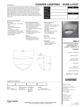
Diagnostics Display
The Self-test/Self-diagnostics provides visual indication of
unit status via a multi-colored LED. The LED may indicate just
one or any combination of the various conditions as follows:
DIAGNOSTIC
CHARGE
TEST
Steady Green :
Flashing Green :
Steady Yellow :
Flashing Yellow :
Steady Red :
Flashing Red :
Normal Operation
AC Interruption in Last 48 Hours
Lamp Circuit Malfunction
Self-test or Manual Test in Progress
Battery Failed Testing
Battery Disconnected or
Charger Malfunction
Battery Unit LEDs
and Test Switch
Configuration
RSL Series
Installation Instructions
10070255 REV 1 - 02/22 6 800-533-3948 www.barronltg.com
/