Page is loading ...

IMPORTANT SAFEGUARDS
READ AND FOLLOW ALL SAFETY INSTRUCTIONS.
When using electrical equipment, basic safety precautions should always be followed including the following:
• DISCONNECT AC POWER SUPPLY BEFORE SERVICING.
• Installation and servicing of this equipment should be performed by qualified service personnel only.
• Ensure that the electrical wiring conforms to the National Electrical Code NEC® and local regulations, if
applicable.
• Do not mount near gas or electric heaters.
• Equipment should be mounted in locations and at heights where it will not be readily subjected to tampering
by unauthorized personnel.
• The use of accessory equipment not recommended by the manufacturer may cause an unsafe condition.
• Any modification or use of non-original components will void the warranty and product liability.
• Do not use this equipment for other than intended use.
• Allow battery to charge for 48 hours before first use.
SAVE THESE INSTRUCTIONS!
Technical Support ■ (623) 580-8943 ■ [email protected]
CP-EMW Series
Installation Instructions
10070140 REV 8 - 07/22 1800-533-3948 www.barronltg.com

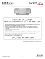
Wall Mount
1. Remove the lens cover by loosening the (4) #8-32 x 3/8” screws (A) and
set aside. (Fig. 1)
2. Remove the housing by loosening the (2) #8-32 x 1/4“ screws (B) and set
aside.
3. Remove the battery by loosening the velcro strap. (Fig. 2)
4a. Wall Mount - Remove the center knockout and any desired knockouts for
mounting to the J-box located in the backplate and the corresponding
knockouts on the supplied gasket. Apply the gasket to the back of the
backplate, as shown. Mount the backplate assembly to the J-box.
4b. Wall Mount with conduit - Remove the desired knockouts on the
backplate and the corresponding knockouts on the supplied gasket. Apply
the gasket to the back of the backplate, as shown. Mount the backplate
assembly to the wall using appropriate hardware for the mounting surface.
Remove the conduit access plug and install a 1/2” NPT liquid-tight fitting
(not provided).
5. For additional mounting support, remove additional knockouts and use
appropriate hardware for mounting surface. (Fig. 3)
6. All electrical connections should be made inside the
junction box. Make electrical connections as follows:
120VAC 277VAC
White - Common White - Common
Black - 120VAC Orange - 277VAC
Green - Ground Green - Ground
Note: Cap unused leads to prevent shorting.
7. Secure the battery using the velcro strap.
8. Secure the housing using the (2) #8-32 x 1/4“ screws from
before.
9. Secure the lens cover using the (4) #8-32 x 3/8” screws
from before.
10. To weatherproof your fixture, be sure to seal all holes in
the housing (mounting, conduit, plugs, etc.) with silicone
sealant. Apply sealant across the top edge to prevent
water from reaching the back of the housing.
Lens Cover
Housing
Fig. 1 (A) x4
#8-32 x 3/8”
(B) x2
#8-32 x 1/4”
Battery
Velcro
Strap
Knockout
Conduit Access Plug
Fig. 2
White (Common)
Black (120V)
Orange (277V)
Green
(Ground)
Transformer
Fig. 3
Gasket
Backplate
Backplate
CP-EMW Series
Installation Instructions
10070140 REV 8 - 07/22 2 800-533-3948 www.barronltg.com

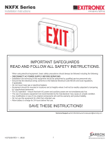
Pole or I-beam Mounting (Option)
Note: The universal bracket is an accessory and needs to
be ordered separately.
1. Follow steps 1-4b under Wall Mount.
2. Remove the (4) knockouts in the backplate and gasket
that align with the universal bracket. (Fig. 4)
3. Secure the universal bracket with (4) 1/4”-20 screws
1/2” – 1” in length (not provided).
4. Unit can be installed using steel banding for routing
around the poles and I-beam. Standard banding 3/4" in
width or less can be used (not provided).
5. Follow steps 6-10 under Wall Mount.
Fig. 5
Fig. 4
Backplate
Gasket
Steel Band
(Not provided)
Universal
Bracket
(Option)
POLE OR I-BEAM MOUNTING
POLE OR I-BEAM MOUNTING
Weatherproof Seal
Steel Band
(Not provided)
Conduit Access Plug
CP-EMW Series
Installation Instructions
10070140 REV 8 - 07/22 3 800-533-3948 www.barronltg.com

Self-Test/Self-Diagnostics (G2)
I M P O R T A N T: Once all emergency lamps have been connected to the unit equipment, apply normal AC power and
charge for 48 hours.
Following installation and after AC power has been supplied, charge for 48 hours, then press and hold the test button until
the LED indicator turns orange. This calibrates the unit equipment for the proper load.
CAUTION: This equipment provides reduced current levels when higher voltage loads are connected. The derangement
signal requires calibration to ensure proper operation.
Operation
The purpose of this option is to provide Self-testing and Self-diagnostic capabilities to the emergency unit. At
predetermined intervals, the emergency unit will automatically switch into battery mode. Refer to the Self-Test Feature
section below for timing details. The emergency unit will also perform various Self-diagnostic tests to determine if there
are any faults. Visual signaling will alert maintenance personnel to a fault of the emergency unit electronics, battery,
and/or battery charger. The circuitry continuously monitors the operating condition of the emergency unit and battery
charging circuit/battery supply voltage. Refer to the LED Indicator section below for fault reporting details.
Self-Test Feature
• The emergency unit will automatically switch to battery mode every month for a period of 1 minutes.
• The emergency unit will automatically switch to battery mode every 6 months for a period of 30 minutes.
LED Indicator
The LED indicator of the emergency unit will display a visual signal indicating the status of the unit. Refer to the table
below for LED indication conditions:
Test Button Features
MANUAL TEST – Pressing the test button will switch the unit into battery mode for a set amount of time. The desired
length of the test is determined by the length of time that the test button is pressed.
• Pressing the test button once will switch the unit into battery mode for a period of 2 seconds.
• Pressing and holding the test button until the LED indicator turns orange will switch the unit into battery mode for a
period of 30 minutes.
• Pressing and holding the test button until the LED indicator flashes red/green will switch the unit into battery mode
for a period of 90 minutes.
Pressing the test button once while the unit is MANUAL TEST mode will cancel the manual test and return the unit to
normal AC power.
RESET – Pressing the test button 3 times will reset the red “UNIT ALERT” LED. If multiple faults are present, it may be
necessary to repeat this procedure for each remaining fault indicated by the “UNIT ALERT” LED.
Use in accordance with local building codes.
LED Indication
Steady
Pulse
Steady
Pulse
Steady
Pulse
LED Color
LED Color
Green
Green
Red
Red
Orange
Orange
Red/Green
Unit Condition
Float Charge
Hi-Rate Charge
Low Batt Voltage
Emer Lamp Failure
No AC Power
Charge Failure
1 Minute Test
Batt Disconnected
30 Minute Self Test
Comment
Batt Fully Charged
Batt Under High-Rate Charge
Replace Battery
Check AC Connection
Replace Transformer
1 Min Test Every Month
Check Batt Connections
30 Min Test Every 6 Months
Replace Damaged or
Missing Lamps
CP-EMW Series
Installation Instructions
10070140 REV 8 - 07/22 4800-533-3948 www.barronltg.com
/