Page is loading ...

Catalog #
Project
Comments
Prepared by
Type
Date
Sure-Lites
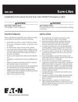
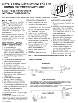
The LPX combo series is a UL 924 code compliant solution for exit and
emergency requirements and is designed to operate for a minimum of
90 minutes during a power outage. Features include a polycarbonate
housing, LED sources for both the exit letters and the emergency heads,
as well as a labor saving self-diagnostic option that automatically
performs required NFPA testing. The Exit is field configurable for either
red or green letters. The LED emergency heads are available with 25
feet or 50 feet of egress coverage. The LED sources and nickel cadmium
battery require no maintenance. Product options include exits or combos
with remote capacity that can be used for extended run times or to power
Sure-Lites SRP/SRM LED remotes.
SPECIFICATION FEATURES
Electrical
General Features
- Field selected red and green sign
letters standard on all units
(units shipped red, field
convertible
to green with supplied parts).
- Dual Voltage Input 120/277 VAC,
60 Hz
- 240 VAC capable with 48 hour
rechargable time
- Sure-Lites EZ Key patented
external battery disconnect
feature – prevents
unnecessary battery drainage,
saves on installation time
- Solid-state voltage limited
charger
- Brownout circuit
- Low-voltage disconnect
- Test switch/power indicator light
- Standard 24 hour recharge
time (max)
- Self-Diagnostic
feature available as an option
- Laser test capability with Self-
Diagnostic
Remote Capacity
- Remote capacity is available in
the combo (3 watts) or the exit (5
watts)
- Remote capable versions are
compatible with the Sure-Lites
SRM and SRP series
Emergency Heads
- LED emergency heads are
available with 100 lumens/head
(25 feet of coverage) or 200
lumens/head (50 feet of
coverage) of emergency light
output.
- Heads can be mounted to top or
sides of exit
Housing Construction
- All components are injection
molded, color stable, high impact
UL 94-5VA rated polycarbonate
material
- White or black textured finish
standard
- Components are of snap-fit
construction to enable under
5-minute installation
- Molded-in wireways facilitate
internal wire routing and
connections
- Field adjustable snap-out or
snap-in chevron directional
indicators have full 3/4” stroke
- Knockout provided on housing
for surface attachment mount
install
- Universal exits can be field
configured as single face or
double face
- Snap-fit canopy with captive
mounting screws included with
all exits
- Combo can be ceiling, wall, or
end mounted
- Universal J-box mounting pattern
Code Compliance
- UL 924 Listed
- UL Damp Location (0° C - 40° C)
- Life Safety NFPA 101
- NEC/OSHA
- Most State and Local Codes
- California Energy Code
Warranty
- Fixture: 5-Year
- Battery: 7-year pro-rata
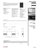
LPXC SERIES
DESCRIPTION
13"
330
7 1/2"
191
2 1/8"
54
13"
330
19 3/4"
502
2 1/8"
54
POLYCARBONATE COMBO
SURFACE MOUNT
LED LAMPS
EMERGENCY EXIT
LIGHTING
SELF DIAGNOSTICS
REMOTE CAPACITY
NICKEL CADMIUM
BATTERY
TD505032EN
2017-9-1
Input Voltage Input Power
120 Volts 2.2 watts
240 Volts 2.5 watts
277 Volts 3.2 watts
ENERGY DATA
LPXC LPX

Sure-Lites
LPX/LPXC SERIES
CATALOG LOGIC
Series Coverage Remote Capacity Color Self Diagnostics Full Catalog Logic
LPXC = LED polycarbonate Combo 25 = 25 feet _ = 0 watts
R3 = 3 watts
_ = white _= no self diagnostics
SD = self diagnostics
LPXC25, LPXC25R3,
LPXC25SD, LPXC25R3SD
LPXC = LED polycarbonate Combo 25 = 25 feet _ = 0 watts
R3 = 3 watts
BK = black SD = self diagnostics
( standard )
LPXC25BKSD,
LPXC25R3BKSD
LPXC = LED polycarbonate Combo 50 = 50 feet not available _ = white
BK = black
SD = self diagnostics
( standard )
LPXC50SD, LPXC50BKSD
LPX = LED polycarbonate Exit not applicable R5 = 5 watts _ = white
BK = black
SD = self diagnostics
( standard )
LPXR5SD, LPXR5BKSD
REMOTE LOGIC
SEL Series Outdoor Capable Remotes
Series SRPA Single Head Remotes Double Head Remotes
Catalog number SRPA29 SRP/SRM13 SRP/SRM25 SRP/SRM30 SRP25D/
SRM25D
SRP50D/
SRM50D
SRP60D/
SRM60D
Watts Consumed 3.5 1.25 2.5 4.1 2.5 5 8.2
Catalog Number Remote
Watts
Available
# of SRPA29
remotes
fixture will
power
# of SRP/
SRM13
remotes
fixture will
power
# of SRP/
SRM25
remotes
fixture will
power
# of SRP/
SRM30
remotes
fixture will
power
# of SRP25D/
SRM25D
remotes
fixture will
power
# of SRP50D/
SRM50D
remotes fixture
will power
# of SRP60D/
SRM60D
remotes fixture
will power
LPXC25R3 3 NA 2 1 NA 1 NA NA
LPXR5 5 1 4 2 1 2 1 NA
SRP SRPD SRM SRMD
SRPA WHITE SRPA BLACK SRPA BRONZE SRPA SILVER

Sure-Lites
LPX/LPXC SERIES
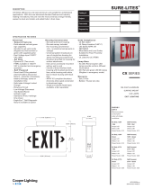
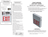
PHOTOMETRY
***The “Rule of Thumb” spacing guidelines are designed to achieve 1 foot-candle average and 0.1 foot-candle minimum with a 40:1 maximum/minimum ratio. The
corridor used is 100 feet long, 9 foot ceiling with a 6 foot wide walkway and 3 foot path of egress. The reflectances are 80% ceiling, 50% walls and 20% floors. The
fixture mounting height is 7.5 feet. Eaton assumes no responsibility for local requirements or specific project variables. This is a guideline to be used as a design aid, not as
guarantee of any code compliance.
50ft
1 2
34
1.2
1.3 2.2 3.3 3.7 3.0 1.9 1.2 0.7 0.4 0.3 0 .2 0. 1 0.1 0.1 0.1 0.1 0.1 0.1 0 .1 0. 1 0.1 0.1 0.1 0.2 0.3 0.4 0.7 1.2 1.9 3.0 3.7 3.3 2.2 1.3 1 .8
1.2 2.0 3.0 3 .5 3. 0 2.0 1.2 0.7 0.5 0.3 0.2 0.1 0.1 0.1 0.1 0.1 0.1 0.1 0 .1 0. 1 0.1 0.1 0.1 0.2 0.3 0.5 0.7 1.2 2.0 2.9 3.5 3.0 2.0 1.2 1 .7
0.9 1.3 1.9 2 .3 2. 1 1.6 1.1 0.7 0.4 0.3 0.2 0.1 0.1 0.1 0.1 0.1 0.1 0.1 0 .1 0. 1 0.1 0.1 0.1 0.2 0.3 0.4 0.7 1.1 1.6 2.1 2.3 1.9 1.3 0.9 1 .1
LPXC50
X Y Z Orient Tilt
24.25 0.33 7. 5 158 40
24.75 0.33 7. 5 22 40
74.75 0.3 7. 5 22 40
74.25 0.292 7. 5 158 40
50 ft.
25ft
3
.1
1
4
.1
1
.1
5
1
6
.1
1
7
.1
1
8
.1
1
9
.1
1
.1
10
1
2.5 1. 5 1.5 2.5 2 .7 1.8 0.8 0 .4
0.2
0.2
0.2
0.2 0.3 0.5 1.1 2.2
2.9 2.1 1.4 1.7 2.8 2.5 1. 4 0.7 0.3
0.2
0.2 0.2 0 .2 0.3 0.7 1 .4 2.5 2.8 1 .7 1.4 2.1
2.9 2.2 1.1 0.5 0.3 0.2 0.2
2.3 1. 4 1.4 2.3 2 .5 1.8 0.9 0 .4
0.2 0.2 0 .2 0.2 0.3 0 .6 1.2 2.1 2 .6 1.9 1.2 1 .6 2.5 2.3 1 .5 0.7 0.4
0.2 0.2
0.2
0.2 0.4 0.7 1.5 2.3 2.5 1. 6 1.2 1.9 2. 6 2.1 1.2 0. 6 0.3 0.2
0.2
1.2 0. 9 0.9 1.2 1 .5 1.2 0.7 0 .4
0.2
0.2
0.2
0.2 0.3 0.5 0.9 1.3 1 .4 1.1 0.9 0 .9 1.3 1.4 1 .0 0.6 0.3 0.2
0.2 0.2 0 .2 0.3 0.6 1 .0 1.4 1.3 0 .9 0.9 1.0 1 .4 1.3 0.8 0 .5 0.3
0.2 0 .2
LPXC25
X Y Z Orient Tilt
-0.5 0.25 7. 5 125 27
0.5 0.25 7. 5 55 27
16.5 0.211 7. 5 125 27
1 7. 5 0.212 7. 5 55 27
33.5 0.172 7. 5 125 27
34.5 0.173 7. 5 55 27
50.5 0.132 7. 5 125 27
51.5 0.135 7. 5 55 27
67.5 0.093 7. 5 125 27
68.5 0.096 7. 5 55 27
84.5 0.054 7. 5 125 27
85.5 0.058 7. 5 55 27
101.5 0.015 7. 5 125 27
102.5 0.019 7. 5 55 27
25 ft.

Sure-Lites
LPX/LPXC SERIES
TECHNICAL DATA
Exit Lamps
LPXC Series Exits use energy efficient, long life
LED’s to provide uniform diffuse illumination of
the exit face. These red and green LEDs require
no maintenance and consume less than one
watt, on average. The LED’s are powered from
AC input during normal operation and from the
battery during a power outage.
Emergency Heads
The LPXC series features long life LED’s for the
emergency source. These LED’s require no
maintenance and are available with 100 lumens/
head or 200 lumens/head output. The heads are
adjustable and can be mounted on the top or
side of the exit housing.
Housing Construction
Rugged, durable, injection molded
polycarbonate materials are used throughout
the LPXC Series. All structural components
are designed with reinforcing ribs to add
additional rigidity and to maximize structural
integrity. These materials are impact and
scratch resistant, and they have been UV
stabilized to resist discoloration due to age
and ultraviolet radiation. All components are
designed to be of snap-fit construction - no
mechanical fasteners – to facilitate installation
in under 5-minutes. Any components required
for installation (wirenuts, wire leads, universal
metal J-box bracket, etc.) are all included. The
universal design of the LPXC Series enables
exits to be configured as single face or double
face in the field. All LPXC series Combo’s can
be wall, ceiling, or end mounted; a rugged,
snap-fit, low profile canopy with captive screws
is included with every exit for ceiling and end
mounting application.
Lens
Lenses for the LPXC Series are made from
durable, impact resistant polycarbonate. All exit
faces are designed with full 3/4” stroke snap-out
or snap-in chevron directional indicators to
insure maximum visibility and compliance with
the latest codes. Units come with red lenses
installed and green lenses included for field
selectable red or green signs.
Brownout Circuit
The brownout circuit on Sure-Lites’ exits
monitors the flow of AC current to the exit and
activates the emergency lighting system when a
predetermined reduction of AC power occurs.
This dip in voltage can cause fixtures to
extinguish resulting in a loss of normal lighting
even though a total power failure has not
occurred.
Solid-State Transfer
The LPXC Series incorporates solid-state
switching which eliminates corroded and pitted
contacts or mechanical failures associated with
relays. The switching circuit is designed to
detect a loss of AC voltage and automatically
energizes the lamps using DC power. Upon
restoration of AC power, the DC power will be
disconnected and the charger will automatically
recharge the battery.
Low Voltage Disconnect
When the battery’s terminal voltage falls, the
low-voltage circuitry disconnects the lighting
load. The disconnect remains in effect until
normal utility power is restored, preventing
deep battery discharge.
EZ Key – External Power
Disconnect
The EZ Key is an external power disconnect.
The patent EZ Key technology keeps the
battery disconnected during the construction
cycle. This prevents battery wear and
ensures the battery maintains its charge for
the inspection process. Simply remove the
key once the building is commissioned.
Test Switch/Power Indicator Light
A test switch located on the side of the exit
permits the activation of the emergency circuit
for a complete operational systems check. The
Power Indicator Light provides visual assurance
that the AC power is on.
Sealed Nickel Cadmium Battery
Sure-Lites sealed nickel cadmium batteries are
maintenance-free with a life expectancy of 10
years. The sealed rechargeable nickel cadmium
battery offers high discharge rates and stable
performance over a wide range of temperatures,
from 0° C to 40° C (32 F to 104 F).
Self Diagnostics Option
The self-diagnostic unit will automatically
perform all tests required by UL924, and NFPA
101. The system indicates the status of the
fixture at all times using the LED indicator
near the test switch on the side of the unit. A
90 minute battery power (emergency mode)
simulation test will occur every 12 months. A 30
second battery power simulation test will occur
every 30 days.
Laser Test
The Self-Diagnostic option include a laser
pointer testing cability. Activation of the
photocell test button with a laser pointer will
simulate loss of AC power and engage the
emergency operation of the exit and emergency
heads.
Warranty
All Sure-Lites’ products are backed by a firm
five-year warranty against defects in material
and workmanship. Maintenance-free, long-life,
sealed nickel cadmium batteries carry a seven-
year pro-rata warranty.
EZ Key Laser tester
Part Number = LASER
(sold separately)

Sure-Lites
LPX/LPXC SERIES
TD505032EN
2017-9-6
Eaton
1121 Highway 74 South
Peachtree City, GA 30269
P: 770-486-4800
www.eaton.com/lighting
Specifications and
dimensions subject to
change without notice.
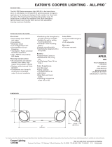
SELF DIAGNOSTIC TESTING OPERATIONS
The Sure-Lites Eagle Eye Self Diagnostics is continuously monitoring your emergency fixture, and will signal any failure through the 3 color
indicator LED.
Initial Operation:
When the unit is first powered up it will go into a 24 hour fast charge and the indicator LED will pulse green. Once the unit has fully charged it
will perform a self calibration. After self calibration, the LED will change to steady green indicating the unit is fully charged and float charging
the battery to maintain readiness.
Automatic Testing:
The unit will perform a battery capacity, lamp/LED, and charge circuit test every 30 days for 30 seconds. During this time, the indicator LED will
change to a steady yellow. It will perform a full battery capacity (90 minute) test once per year. During this time, the indicator LED will change to
a blinking yellow.
Manual Testing:
• 10 Second “Installation” test – Press and release the test button once during fast charge (blinking green) to initiate a 10 second quick test. The
sign will switch to emergency mode for 10 seconds allowing the installer to verify proper installation of the unit, and the LED indicator will
turn solid yellow.
• 30 Second Test - Press and release the test button once during float charge (steady green). The indicator LED will turn steady yellow to
indicate the unit is performing a 30 second test of the batteries and lamps/LEDs.
• 90 Minute Test - Press and release the test button a second time during a 30 second test (steady yellow) to change to a 90 minute test. During
this test, the LED indicator will change to blinking yellow, and the circuit will perform a full battery capacity, charge circuit, and LED test.
• Canceling Test – Press and release the test button during the 90 minute test (flashing yellow) to return the fixture to its original state (fast
charge or float charge)
Laser Test:
The SEL SD products are equipped with a Laser Test function that allows the unit to be manually tested without the need to physically press the
test button. Shining a laser pointer in the hole marked “LASER TEST” on the bottom of the unit has the same effect as a press and release of
the test button.
Clearing Failure Codes:
• A battery failure (LED two blink red) can be cleared by replacing the battery. Disconnecting the battery and AC power, or performing a full
90 minute discharge will reset the error code, however, it will return if the battery is faulty
• Charge Circuit (LED three blink red) and lamp/LED failure (LED four blink red) will clear when the unit successfully passes a manual or
automatic 30 second test.
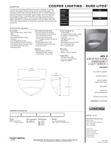
SELF DIAGNOSTIC TESTING OPERATIONS
Indicators:
• LED Off - No power to unit, emergency mode.
• LED Steady Green - Unit is fully charged and is float charging the battery to maintain readiness.
• LED Green Pulse - Unit is in a 24 hour fast charge of the battery.
• LED Two Blink Red - Battery has failed a capacity test, or the battery is disconnected. See “Clearing Failure Codes” above.
• LED Three Blink Red - Battery charge circuit has failed. See “Clearing Failure Codes” above.
• LED Four Blink Red - Lamps have burned out, or on an EXIT/Combo, 50% or more of the LEDs have failed. See “Clearing Failure Codes” above.
• LED Steady Yellow - 30 second test or 10 second quick test (Fast Charge only).
• LED Blinking Yellow - 90 minute test.
Maintenance:
None required. Replace the batteries as needed according to ambient conditions. However, we recommend that the equipment be tested
regularly in accordance with local codes.
OFF - EMERGENCY
MODE / POWER OFF
2 BLINK RED -
BATTERY FAILURE
STEADY GREEN -
FULL / FLOAT
CHARGE
STEADY BLINK YELLOW
- 90 MINUTE TEST
3 BLINK RED - CHARGE
CIRCUIT FAILURE
4 BLINK RED - LAMP/
LED FAILURE
STEADY YELLOW -
QUICK TEST
STEADY BLINK
GREEN - FAST
CHARGE
SURE-LITES
/