KVH TracPhone V3 Operating instructions

Type
Operating instructions

This manual is also suitable for

KVH, TracPhone, and the unique light-colored dome with dark contrasting baseplate are registered trademarks of KVH Industries, Inc.
All other trademarks are property of their respective companies. The information in this document is subject to change without notice.
No company shall be liable for errors contained herein. © 2011-2018 KVH Industries, Inc., All rights reserved. 54-0757 Rev. D | 72-0489
1
Replacement Steps
1. Remove the Radome ............................. 2
2. Identify the Gyro Location................... 2
3. Replace the Gyro.................................... 3
4. Update the Software ............................. 7
5. Calibrate the Gyros................................ 9
Tools Required
This procedure requires the following tools:
#1 and #2 Phillips screwdrivers
•Cutting pliers
5/16" nut driver or wrench
5/16" open-end wrench and 5/16" torque wrench set to 8 in.-lbs
(for skew gyro replacement only)
Heat gun or electrical tape
Laptop PC with the latest TracPhone V3-IP/V3-HTS ICM/antenna software or TracPhon
e
V-se
ries Flash Wizard
Important - Please Read!
To perform the calibration step at the end of this procedure, the vessel must remain stationary in
calm seas.
Avoid causing sharp bends in cables when securing or routing cables in this procedure. Sharp
bends or kinks in cables can degrade antenna performance. Also be sure to trim the excess
portion of any tie-wraps you install and collect all trimmings from the antenna to avoid damage.
Gyros are sensitive to shock. Handle the gyro carefully to avoid damage.
Technical Support
If you need technical assistance, please contact KVH Technical Support:
Europe, Middle East, Africa, Asia-Pacific:
Phone: +45 45 160 180
North/South America, Australasia:
Phone: 1 866 701-7103 (U.S. only) or +1 401 851-3806
TracPhone
®
V3/V3IP/V3HTS Gyro
Replacement Instructions
The following instructions explain how to replace a gyro in a TracPhone V3/V3-IP/V3-HTS
antenna.
2
Step 1 - Remove the Radome
a. Disconnect all power from the TracPhone
system– turn off and unplug the ICM
(V3-IP/V3-HTS) or control unit and modem
(V3).
b. Remove the three #10-32 screws securing the
radome to the baseplate (see Figure 1). Set the
radome and screws aside in a safe place.
Step 2 - Identify the Gyro Location
Identify the location of the gyro you need to
replace (see Figure 2). Then follow the associated
instructions in Step 3:
CAUTION
For your own safety, be sure to disconnect
power from all wired components before
performing this procedure.
Gyro Go to Page:
Azimuth 3
Elevation 4
Skew 5
#10-32 Screw (x3)
Figure 1: Radome Screws
Skew
Elevation
Azimuth
Figure 2: Gyro Locations (V3-IP Shown)
3
Step 3 - Replace the Gyro
Replacing the Azimuth Gyro
a. Carefully strip back the heat shrink covering
the gyro wires’ in-line connector (see
Figure 3).
b. Disconnect the gyro wires’ connector.
c. Using a 5/16" nut driver or wrench, remove
the #6-32 lock nut securing the P-clip that
guides the gyro wires to the connector.
Remove and save the P-clip and lock nut.
d. From the front of the reflector, remove the
two #6-32 screws securing the gyro bracket to
the reflector (see Figure 3).
e. Using a #1 Phillips screwdriver, remove the
two M2.5 screws and four shoulder washers
(if present) securing the gyro to the bracket
(see Figure 4). Discard the old gyro, screws,
and shoulder washers.
f. Attach the replacement gyro to the bracket
with two M2.5 screws (supplied in the kit) as
shown in Figure 4. Be sure to orient the gyro
so that its wires will face the reflector.
g. Reattach the bracket to the reflector with two
#6-32 screws (supplied in the kit) (see
Figure 3).
h. Route the gyro wires as shown in Figure 3
and connect them to the in-line connector.
Protect the connection with heat shrink
tubing or electrical tape.
i. Secure the gyro wires in place using the
P-clip you removed earlier (see Figure 3).
Ensure the flat side of the P-clip is against the
reflector.
j. Update the software as explained on page 7.
k. Calibrate the gyros as explained on page 9.
In-line Connector
#6-32 Lock Nut
#6-32 Screw (x2)
Azimuth Gyro
P-clip
Figure 3: Azimuth Gyro Connector (V3-IP Shown)
Azimuth Gyro
M2.5 Screw (x2)
Shoulder Washer (x4)
(not used with
replacement gyro)
Figure 4: Azimuth Gyro Bracket, Screws, and Washers (if present)
Do not overtighten the M2.5 screws when you
attach the replacement gyro. Overtightening
will strip the inside threads of the gyro.
IMPORTANT!
4
Replacing the Elevation Gyro
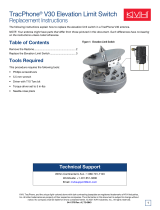
a. Cut and remove the tie-wrap securing the
elevation and azimuth gyro cables to the
cable bundle (see Figure 5).
b. Carefully strip back the heat shrink covering
the elevation gyro wires’ in-line connector
(see Figure 5 and Figure 6).
c. Disconnect the gyro wires’ connector.
d. Remove the tape securing the elevation gyro
wires to the azimuth gyro cable (see
Figure 6).
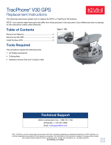
e. Remove the #6-32 screw securing the P-clip
that secures the elevation gyro wires to the
azimuth gyro cable (see Figure 7). Remove
and discard the P-clip and screw.
f. Using a #1 Phillips screwdriver, remove the
two M2.5 screws, four shoulder washers (if
present), and two M2.5 standoffs securing the
gyro to the antenna frame (see Figure 7).
Discard the old gyro, screws, and shoulder
washers.
g. Attach the replacement gyro to the frame
with two new M2.5 screws and two M2.5
standoffs (supplied in the kit) (see Figure 7).
Be sure to orient the gyro so that its wires are
on top.
h. Route the gyro wires as shown in Figure 6
and connect them to the in-line connector.
Protect the connection with heat shrink
tubing or electrical tape.
i. Secure the gyro wires in place using a new
P-clip and #6-32 screw (supplied in kit) as
shown in Figure 7.
j. Wrap the gyro wires and azimuth gyro cable
with the supplied tape at the location shown
in Figure 6. This tape will protect the wires
from abrasion.
Elevation Gyro
In-line Connector
Tie-wrap
Tape
Azimuth Gyro Cable
Elevation Gyro Cable
Figure 5: Secured Gyro Cables (V3-IP Shown)
In-line Connector
Elevation Gyro
P-clip
Tape
Azimuth Gyro Cable
Figure 6: Elevation Gyro Connector
Figure 7: Elevation Gyro Screws and Washers (if present)
Do not overtighten the standoffs when you
attach the replacement gyro. Overtightening
will strip the inside threads of the gyro.
IMPORTANT!
5
k. Using a tie-wrap, secure the elevation and
azimuth gyro cables to the cable bundle in the
location shown in Figure 5 on page 4.
l. Update the software as explained on page 7.
m. Calibrate the gyros as explained on page 9.
Replacing the Skew Gyro
a. Carefully strip back the heat shrink covering
the gyro wires’ in-line connector (see
Figure 8).
b. Disconnect the gyro wires’ connector.
c. Using a 5/16" open-end wrench, disconnect
the BUC cable from the OMT (see Figure 8).
d. Cut and remove the two tie-wraps and tape
securing the gyro wires to the motor wires,
BUC cable, and RF cable (see Figure 8).
e. Using a 5/16" nut driver or wrench, remove
the two #6-32 lock nuts securing the gyro’s
mounting plate to the skew assembly (see
Figure 9). Detach the mounting plate from
the skew assembly.
f. Using a #1 Phillips screwdriver, remove the
two M2.5 screws securing the gyro to the
mounting plate (see Figure 10). Discard the
old gyro and screws.
g. Attach the replacement gyro to the mounting
plate with two M2.5 screws (supplied in the
kit) (see Figure 10).
h. Reattach the mounting plate to the skew
assembly with two #6-32 lock nuts (supplied
in the kit) (see Figure 9). Be sure to orient the
gyro so that its wires are on the left.
i. Loop the gyro wires as shown in Figure 8 and
connect them to the in-line connector. Protect
the connection with heat shrink tubing or
electrical tape.
Tie-wrap
Tie-wrap
Tape
Tape
In-line Connector
Skew Gyro
RF Cable
BUC Cable
Motor Wires
OMT
Figure 8: Skew Gyro Connector (V3-IP Shown)
Mounting Plate
Skew Gyro
#6-32 Lock Nut (x2)
Figure 9: Gyro Mounting Plate Attached to Skew Assembly
Mounting Plate
Skew Gyro
M2.5 Screw (x2)
Figure 10: Skew Gyro Attached to Mounting Plate
Do not overtighten the M2.5 screws when you
attach the replacement gyro. Overtightening
will strip the inside threads of the gyro.
IMPORTANT!
6
j. Wrap the gyro wires and motor wires with
the supplied protective tape (once around) at
the location shown in Figure 8 on page 5.
Then secure them together with a tie-wrap.
k. Reconnect the BUC cable to the OMT (see
Figure 8 on page 5). Hand-tighten, then
tighten with a 5/16" torque wrench set to
8 in.-lbs.
l. Wrap the gyro wires, motor wires, BUC
cable, and RF cable with the supplied
protective tape (once around) at the location
shown in Figure 8 on page 5. Then secure
them together with a tie-wrap.
m. Update the software as explained on page 7.
n. Calibrate the gyros as explained on page 9.
7
Step 4 - Update the Software
Follow these steps to ensure the latest software is
installed in the TracPhone system.
The software update process differs depending
on antenna model:
TracPhone V3-IP/V3-HTS - see below
TracPhone V3 - refer to page 8
TracPhone V3-IP/V3-HTS
This procedure explains how to update the software
using the TracPhone V3-IP/V3-HTS web interface.
However, you can also update the software using the
mini-VSAT iPhone
®
/iPod Touch
®
app, a USB drive,
or, if the system is activated, via the antenna’s
Internet connection (airtime charges may apply).
Details are available in the Help.
Check the current software version as follows:
a. Go to the TracPhone V3-IP/V3-HTS web
interface and click the Updates tab. Note the
displayed ICM/Antenna software version
(see Figure 11).
b. If the reported software version is earlier than
the latest version you downloaded from the
KVH Partner Portal, update the system
following the steps below.
Update the software as follows:
a. Click Choose File.
b. At the Login window, enter the
Administrator password.
c. Click Browse and navigate to the file you
saved on your laptop (see Figure 12).
d. Click Check File.
e. At the confirmation message, click Update.
Wait for the software update to complete. It
might take up to 40 minutes.
Figure 11: Updates Page on ICM Web Interface
Figure 12: Update File Selected for Upload (V3-IP Shown)
8
TracPhone V3
Check the current software version as follows:
a. At the control unit, press MENUS until the
display shows “ANTENNA STATUS” (see
Figure 13). Then press ACCEPT.
b. Press MENUS until the display shows
“ANTENNA MAIN BOARD.” Note the
reported software (SW) version.
c. Press MENUS to view the software versions
for the RF board, AZ/EL motor, skew motor,
and control unit. Note all of these versions.
d. Compare the software versions you just
noted on the control unit with the latest
versions listed in the TracPhone V-series
Flash Wizard’s Release Notes.
NOTE: Before using the TracPhone V-series Flash
Wizard, be sure to check for updates to ensure it has
all of the latest software files (Internet access
required). If you don’t yet have the Wizard installed
on your PC, download it from the KVH Partner
Portal (KVH-certified technicians only).
e. Use the TracPhone V-series Flash Wizard to
update any older versions of software in the
TracPhone system. Refer to the Wizard’s
Help menu for complete details (see
Figure 14).
ANTENNA MAIN BOARD
SW VERSION 2.34
ANTENNA RF BOARD
SW VERSION 1.23
ANTENNA AZ/EL MOTOR
SW VERSION 1.28
ANTENNA SKEW MOTOR
SW VERSION 1.04
CTRL UNIT
SW VERSION 2.14
ANTENNA STATUS
NEXT MENU ACCEPT
Press ACCEPT
Press MENUS twice
PRESS TO VIEW
EACH ANTENNA ITEM
Press MENUS
to scroll through
the status screens
Figure 13: Software Versions Displayed on the Control Unit
Figure 14: TracPhone V-series Flash Wizard Help Menu
9
Step 5 - Calibrate the Gyros
NOTE: Complete calibration details are provided in
the User’s Guide.
The calibration process differs depending on
antenna model:
TracPhone V3-IP-V3-HTS - see below
TracPhone V3 - refer to page 10
TracPhone V3-IP/V3-HTS
NOTE: These instructions assume you will be using
PuTTY to enter antenna commands. However, you
may use a different terminal emulator program, such
as HyperTerminal.
a. Turn on the ICM and wait five minutes for
system startup.
b. Connect your computer to the “User Ethernet
1” port on the rear panel of the ICM.
c. Start PuTTY and enter the ICM’s IP address
and port number (see Figure 15). Select
Telnet for “Connection type” then select
Open to start a Telnet session and open a
command line window.
NOTE: By default, the ICM uses a gateway of
192.168.5.1 and port 50001. You may change these
settings at the ICM’s web interface (see the
instructions in the Installation Guide, User’s Guide,
or Help).
d. At the command line, enter and send the
following commands to the antenna:
•HALT
•DEBUGON
EEUNLOCK
=CALNEWGYRO
Important!
Calibrate the gyros only while the vessel is
stationary in calm seas.
Figure 15: PuTTY Configuration Screen
10
Verify that the calibrations for azimuth (AZ),
elevation (EL), and skew gyros all pass.
e. Enter and send the following command:
•ZAP
f. The system will restart. Wait five minutes for
system startup. Then test the system for
normal operation. If the problem persists,
contact KVH Technical Support.
The replacement procedure is complete!
TracPhone V3
You can calibrate the gyros from the front panel
of the control unit. Turn on the TracPhone
system then follow the steps shown in Figure 16.
The replacement procedure is complete!
Ensure all three gyros pass (“P”).
If any fail (“F”), retry the calibration.
If it continues to fail, contact KVH
Technical Support.
CAL GYRO= YES?
CHANGE ACCEPT
DO NOT MOVE VESSEL
DURING CALIBRATION
DIAGNOSTICS
NEXT MENU ACCEPT
ENTERING DIAGNOSTICS
CAL GYRO= NO
NEXT ITEM CHANGE
CALIBRATING GYROS
AZ:P EL:P SKEW:P
Press MENUS four times
Figure 16: Control Unit Gyro Calibration (V3)
  • Page 1 1
  • Page 2 2
  • Page 3 3
  • Page 4 4
  • Page 5 5
  • Page 6 6
  • Page 7 7
  • Page 8 8
  • Page 9 9
  • Page 10 10

KVH TracPhone V3 Operating instructions

Type
Operating instructions
This manual is also suitable for

Ask a question and I''ll find the answer in the document

Finding information in a document is now easier with AI