Page is loading ...

KVH, TracPhone, and the unique light-colored dome with dark contrasting baseplate are registered trademarks of KVH Industries, Inc.
All other trademarks are property of their respective companies. The information in this document is subject to change without notice.
No company shall be liable for errors contained herein. © 2021 KVH Industries, Inc., All rights reserved.
54-1374 Rev. A | 72-0932 1
TracPhone® V30 Main Board
Replacement Instructions
The following instructions explain how to replace the main board in a TracPhone V30 antenna.
NOTE: Your antenna might have parts that differ from those pictured in this document. Such differences have no bearing
on the instructions unless noted otherwise.
Table of Contents
Remove the Radome......................................................... 2
Replace the Main Board.................................................... 2
Record the Serial Number ................................................. 3
Access the Web Interface ................................................. 3
Update the System Software ............................................ 3
Configure the New Main Board ......................................... 4
Verify Normal Operation .................................................... 4
Tools Required
This procedure requires the following tools:
• #2 Phillips screwdriver
• Driver with T10 Torx bit
• Torque driver set to 9 in-lbs
• ESD wrist strap
• Laptop PC with the latest V30 system software
downloaded from the KVH Partner Portal
(www.kvh.com/partners)
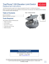
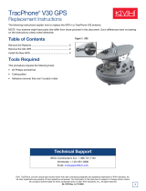
Figure 1: Main Board
Figure 2: Main Board Cable Connections
IMPORTANT!
To perform the calibration steps at the end of this
procedure, the vessel must remain stationary in calm
seas.
IMPORTANT!
Before you begin, contact KVH Technical Support for
the correct limit switch offset values. Later, you will
need to enter these values into the new main board.
Technical Support
Within Continental U.S.A.: 1 866 701-7103
Worldwide: +1 401 851-3806
Email: mvbsupport@kvh.com

2
TracPhone V30 Main Board Replacement
Remove the Radome
Follow the steps below to disconnect power and remove
the radome from the antenna.
1. Power off and unplug the VSAT-Hub to disconnect
power from the antenna.
2. Remove and discard the three #10-32 screws securing
the radome to the baseplate (see Figure ). Carefully lift
the radome straight up until clear of the antenna
assembly and set it aside in a safe place.
NOTE: If you keep the radome topside, secure it with a
lanyard to prevent it from falling overboard. Also, do not
place the radome on a hot steel deck – the heat may warp
the radome.
Figure 3: Radome Screws
Replace the Main Board
Follow the steps below to replace the main board.
1. Put on an ESD wrist strap and connect it to any bare
metal portion of the antenna frame.
2. Disconnect the two Ethernet cables from the main
board (see Figure 4).
Figure 4: Main Board Connectors
3. Disconnect the LMR-240 cable from the main board
(see Figure 4).
4. Using the supplied connector extraction tool,
disconnect the white header connectors from the main
board, with the exception of the main board fan
cable’s connector (see Figure 4 and Figure 2 on
page 1). Be sure to disconnect by grasping the
connector body; do not pull on the wires.
5. Using a T10 Torx screwdriver, remove and discard the
four M3 Torx screws securing the main board to the
antenna frame.
Figure 5: Main Board Screws
6. Carefully remove the main board.
CAUTION
To prevent injury, be sure to disconnect all
power from the antenna before proceeding.
Power must remain disconnected for the
duration of this procedure.
IMPORTANT!
The main board is static-sensitive. Be sure to take the
proper grounding precautions before handling.

3
TracPhone V30 Main Board Replacement
7. Position the replacement main board over the four
mounting holes in the antenna frame. Take care to lay
the main board flat against the frame, and not to pinch,
flatten, or damage any of the loose wires or
connectors.
8. Secure the main board to the frame with four new M3
Torx screws (T10) (supplied in kit) (see Figure 5 on
page 2). Tighten the screws to 9 in-lbs of torque.
9. Carefully reconnect the header connectors to the main
board (see Figure 4 on page 2). Be sure to connect the
cables in their proper locations, as shown in Figure 2
on page 1.
10. Reconnect the two Ethernet cables to the main board
(see Figure 4 on page 2). Be sure to connect the
cables in their proper locations, as shown in Figure 2
on page 1.
11. Apply some silicone grease inside the connector of the
LMR-240 cable and connect it to the main board.
Hand-tighten until the connector is secure (see
Figure 4 on page 2).
Record the Serial Number
Follow the steps below to record the serial number and
replace the radome.
1. Find the antenna serial number label on the frame.
Write down this 9-digit number for later use.
Figure 6: Antenna Serial Number
2. Inspect the inside of the antenna to make sure you
have not left any tools inside.
3. Reinstall the radome onto the antenna and secure it
with three new #10-32 screws (supplied in kit). Tighten
the screws to 5 in-lbs of torque.
4. Reconnect power to the VSAT-Hub.
Access the Web Interface
1. Momentarily press the Reset button on the rear panel
of the VSAT-Hub. The “VSAT-Hub” light should be lit
orange.
Figure 7: VSAT-Hub Reset Button
2. Connect your laptop directly to an available Ethernet
port on the VSAT-Hub.
3. Start a web browser and enter
https://kvhonboard.com. (If the login page does not
appear, try http://192.168.5.1, which is the default IP
address of the VSAT-Hub.)
4. At the login page, enter the following credentials:
• Username: tech
• Password: <VSAT-Hub serial number>
Update the System Software
At the Software Updates page of the web interface, upload
the latest system software that you downloaded from the
KVH Partner Portal.
Figure 8: Software Update Page
NOTE: For details on updating the software, refer to the
system’s Help.

4
TracPhone V30 Main Board Replacement
Configure the New Main Board
Follow these steps to enter the antenna serial number in
the main board, calibrate its accelerometers, and
recalibrate the gyros.
1. At the Tech Tool page of the web interface, enter each
antenna command below. To enter a command, type
the command in the text box then click Send (see
Figure 9).
Figure 9: Tech Tool Page
• HALT
• DEBUGON
• EEUNLOCK
• =SERNUM,<9-digit antenna serial number you
noted earlier> [Example: =SERNUM,210801234]
• SETCALUP,<offset value for elevation limit
switch, in degrees> [Example: SETCALUP,1.3]
•SETCALSKLS,<offset value for skew limit switch,
in degrees> [Example: SETCALSKLS,1.3]
• =CALACCELOFFSET
Verify that the calibrations for x, y, and z
accelerometers all pass.
• =CALNEWGYRO
Verify that the gyro calibration passes.
2. At the Support page of the web interface, select
Restart Hardware > Restart Antenna.
Figure 10: Restart Antenna from Support Page
Verify Normal Operation
Test the system for normal operation. If the problem
persists, contact KVH Technical Support.
The replacement procedure is complete!
/