Page is loading ...

KVH, TracPhone, and the unique light-colored dome with dark contrasting baseplate are registered trademarks of KVH Industries, Inc.
All other trademarks are property of their respective companies. The information in this document is subject to change without notice.
No company shall be liable for errors contained herein. © 2021 KVH Industries, Inc., All rights reserved.
54-1378 Rev. A | 72-0931 1
TracPhone® V30 GPS
Replacement Instructions
The following instructions explain how to replace the GPS in a TracPhone V30 antenna.
NOTE: Your antenna might have parts that differ from those pictured in this document. Such differences have no bearing
on the instructions unless noted otherwise.
Table of Contents
Remove the Radome......................................................... 2
Remove the Old GPS ........................................................ 2
Install the New GPS........................................................... 3
Tools Required
This procedure requires the following tools:
• #2 Phillips screwdriver
• Cutting pliers
• Adhesive remover that won’t scratch metal
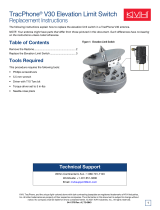
Figure 1: GPS
Technical Support
Within Continental U.S.A.: 1 866 701-7103
Worldwide: +1 401 851-3806
Email: mvbsupport@kvh.com

2
TracPhone V30 GPS Replacement
Remove the Radome
Follow the steps below to disconnect power and remove
the radome from the antenna.
1. Power off and unplug the VSAT-Hub to disconnect
power from the antenna.
2. Remove and discard the three #10-32 screws securing
the radome to the baseplate (see Figure 2). Carefully
lift the radome straight up until clear of the antenna
assembly and set it aside in a safe place.
NOTE: If you keep the radome topside, secure it with a
lanyard to prevent it from falling overboard. Do not place
the radome on a hot steel deck – the heat may warp the
radome.
Figure 2: Radome Screws
Remove the Old GPS
Follow the steps below to remove the defective GPS.
1. Disconnect the GPS cable from the main board (see
Figure 3).
Figure 3: GPS Cable Connection at Main Board
2. Carefully remove the GPS cable from the two metal
retaining clips (see Figure 3).
3. Using cutting pliers, remove and discard the three tie-
wraps securing the GPS cable to the antenna frame
(see Figure 4).
Figure 4: Tie-Wraps 1-3 Securing GPS Cable
CAUTION
To prevent injury, be sure to disconnect all
power from the antenna before proceeding.
Power must remain disconnected for the
duration of this procedure.

3
TracPhone V30 GPS Replacement
4. Remove and discard the two tie-wraps securing the
GPS cable to the clear plastic skew cable wrap cover
and the reflector (see Figure 5).
Figure 5: Tie-Wraps 4 and 5 Securing GPS Cable
5. Remove and discard the rubber grommet from the
reflector (see Figure 5). Simply push the grommet out
through the hole.
6. Extract the entire length of GPS cable up through the
hole in the reflector.
7. Grasp the GPS module and carefully pull it free from
the reflector. Discard the defective GPS.
8. Remove any remaining adhesive residue from the
reflector.
Install the New GPS
Follow the steps below to install the new GPS.
1. Feed the cable of the new GPS down through the hole
in the reflector.
2. Install a new rubber grommet (supplied in kit) to
prevent abrasion from the metal edges of the hole in
the reflector (see Figure 5).
3. Peel off the paper backing from the base of the
replacement GPS module to expose the adhesive.
Then press the GPS module down firmly onto the
reflector in the orientation shown in Figure 6. Apply
pressure to make sure the adhesive bonds to the
reflector.
Figure 6: GPS Orientation on Reflector
4. Using new tie-wraps (supplied in kit), secure the GPS
cable to the reflector and skew cable wrap cover (see
Figure 5).
5. Route the GPS cable to the PCB and use new tie-
wraps to secure it at the locations shown in Figure 4
on page 2.
6. Connect the GPS cable to the PCB (see Figure 3 on
page 2).
7. Secure the GPS cable in the two retaining clips (see
Figure 3 on page 2).
8. Move the reflector up and down through its full
elevation range and make sure the GPS cable does
not become taut or restrict movement. Then tighten all
five tie-wraps and trim the excess.
9. Inspect the inside of the antenna to make sure you
have not left any tools or debris inside.
10. Reinstall the radome onto the antenna and secure it
with three new #10-32 screws (supplied in kit). Tighten
the screws to 5 in-lbs of torque.
11. Reconnect power to the VSAT-Hub.
12. Test the system for normal operation. If the problem
persists, contact KVH Technical Support.
The replacement procedure is complete!
IMPORTANT!
Before tightening any tie-wraps securing the GPS
cable, move the reflector up and down to ensure the
cable does not become taut or restrict movement.
/