Allen-Bradley PowerFlex 700S Quick start guide
- Category
- Power adapters & inverters
- Type
- Quick start guide

Quick Start
PowerFlex
®
700S Adjustable
Frequency AC Drive - Phase II
(Frames 1 - 6)
Introduction This document is designed to guide you through the basic steps needed to
install, start-up, and program the PowerFlex 700S Adjustable Frequency
AC - Phase II drive for Frames 1 - 6. The information provided in this
document does not replace the user manual and is intended for
qualified personnel only. For detailed PowerFlex 700S information refer to
the appropriate publications listed below.
Reference Materials Allen-Bradley publications are available on the internet at:
www.rockwellautomation.com/literature
.
Title Publication
PowerFlex 700S Drives with Phase II Control User Manual 20D-UM006
PowerFlex 700S Drives with Phase II Control Reference Manual PFLEX-RM003
PowerFlex 700S and DriveLogix
™
Firmware Release Notes 20D-RN007
PowerFlex 700H/S High Power Installation Instructions (Frames 9 - 12) PFLEX-IN006
Wiring and Grounding Guidelines for Pulse Width Modulated (PWM) AC Drives DRIVES-IN001


3
Table of Contents
Six Basic Steps to a Successful Start-Up
Step 1 — Read General Information . . . . . . . . . . . . . . . . . . . . . . . . . . . . . . . . .4
General Precautions . . . . . . . . . . . . . . . . . . . . . . . . . . . . . . . . . . . . . . . 4
EMC Instructions . . . . . . . . . . . . . . . . . . . . . . . . . . . . . . . . . . . . . . . . . 5
General Notes. . . . . . . . . . . . . . . . . . . . . . . . . . . . . . . . . . . . . . . . . . . . 6
Step 2 — Mount the Drive . . . . . . . . . . . . . . . . . . . . . . . . . . . . . . . . . . . . . . . . . .7
Minimum Mounting Clearances . . . . . . . . . . . . . . . . . . . . . . . . . . . . . 7
Operating Temperatures . . . . . . . . . . . . . . . . . . . . . . . . . . . . . . . . . . . . 7
Dimensions. . . . . . . . . . . . . . . . . . . . . . . . . . . . . . . . . . . . . . . . . . . . . . 8
Step 3 — Power Wiring . . . . . . . . . . . . . . . . . . . . . . . . . . . . . . . . . . . . . . . . . . .13
Wire Recommendations . . . . . . . . . . . . . . . . . . . . . . . . . . . . . . . . . . . 17
Power & Ground Wiring . . . . . . . . . . . . . . . . . . . . . . . . . . . . . . . . . . 17
Power Terminal Block Designations . . . . . . . . . . . . . . . . . . . . . . . . . 17
Using PowerFlex 700S Drives with Regen Power Units . . . . . . . . . . 18
Step 4 — Control Wiring . . . . . . . . . . . . . . . . . . . . . . . . . . . . . . . . . . . . . . . . . .19
Wiring Recommendations . . . . . . . . . . . . . . . . . . . . . . . . . . . . . . . . . 19
DIP Switch Settings . . . . . . . . . . . . . . . . . . . . . . . . . . . . . . . . . . . . . . 20
I/O Terminal Blocks . . . . . . . . . . . . . . . . . . . . . . . . . . . . . . . . . . . . . . 21
I/O Wiring Examples . . . . . . . . . . . . . . . . . . . . . . . . . . . . . . . . . . . . . 23
Step 5 — Start-Up Check List. . . . . . . . . . . . . . . . . . . . . . . . . . . . . . . . . . . . . .26
Before Applying Power to the Drive . . . . . . . . . . . . . . . . . . . . . . . . . 26
Applying Power to the Drive . . . . . . . . . . . . . . . . . . . . . . . . . . . . . . . 28
Step 6 — Program the Drive – Start-Up . . . . . . . . . . . . . . . . . . . . . . . . . . . . . .30
Assisted Start . . . . . . . . . . . . . . . . . . . . . . . . . . . . . . . . . . . . . . . . . . . 30
Parameter Files & Groups . . . . . . . . . . . . . . . . . . . . . . . . . . . . . . . . . 32
Frequently Used Parameters . . . . . . . . . . . . . . . . . . . . . . . . . . . . . . . 32
Additional Information
ATEX Approved PowerFlex 700S Phase II Drives in Group II Category (2) Appli-
cations with ATEX Approved Motors . . . . . . . . . . . . . . . . . . . . . . . . . . . . . . . .36
DriveLogix™ Recommended Programming Techniques. . . . . . . . . . . . . . . .40
Troubleshooting. . . . . . . . . . . . . . . . . . . . . . . . . . . . . . . . . . . . . . . . . . . . . . . . .41
Abbreviated Fault & Alarm Clearing. . . . . . . . . . . . . . . . . . . . . . . . . 41
HIM Indication. . . . . . . . . . . . . . . . . . . . . . . . . . . . . . . . . . . . . . . . . . 41
Manually Clearing Faults. . . . . . . . . . . . . . . . . . . . . . . . . . . . . . . . . . 41
Technical Support . . . . . . . . . . . . . . . . . . . . . . . . . . . . . . . . . . . . . . . . . . . . . . .42
Online. . . . . . . . . . . . . . . . . . . . . . . . . . . . . . . . . . . . . . . . . . . . . . . . . 42
Telephone . . . . . . . . . . . . . . . . . . . . . . . . . . . . . . . . . . . . . . . . . . . . . . 42

4
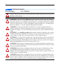
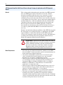
General Precautions
Class 1 LED Product
Step 1 Read General Information
!
ATTENTION: Hazard of permanent eye damage exists when using optical transmission
equipment. This product emits intense light and invisible radiation. Do not look into module ports or
fiber optic cable connectors.
!
ATTENTION: This drive contains ESD (Electrostatic Discharge) sensitive parts and assemblies.
Static control precautions are required when installing, testing, servicing or repairing this assembly.
Component damage may result if ESD control procedures are not followed. If you are not familiar
with static control procedures, reference Allen-Bradley publication 8000-4.5.2, “Guarding Against
Electrostatic Damage” or any other applicable ESD protection handbook.
!
ATTENTION: An incorrectly applied or installed drive can result in component damage or a
reduction in product life. Wiring or application errors such as under sizing the motor, incorrect or
inadequate AC supply, or excessive surrounding air temperatures may result in malfunction of the
system.
!
ATTENTION: Only qualified personnel familiar with the PowerFlex 700S Drive and associated
machinery should plan or implement the installation, start-up and subsequent maintenance of the
system. Failure to comply may result in personal injury and/or equipment damage.
!
ATTENTION: To avoid an electric shock hazard, verify that the voltage on the bus capacitors has
discharged before performing any work on the drive. Measure the DC bus voltage at the +DC & –
DC terminals of the Power Terminal Block (refer to Chapter 1 in the PowerFlex 700S User Manual,
publication 20D-UM006, for location). The voltage must be zero.
!
ATTENTION: Risk of injury or equipment damage exists. DPI or SCANport host products must
not be directly connected together via 1202 cables. Unpredictable behavior can result if two or more
devices are connected in this manner.
!
ATTENTION: Risk of injury or equipment damage exists. Parameters 365 [Encdr0 Loss Cnfg] -
394 [VoltFdbkLossCnfg] let you determine the action of the drive in response to operating
anomalies. Precautions should be taken to ensure that the settings of these parameters do not create
hazards of injury or equipment damage
!
ATTENTION: Risk of injury or equipment damage exists. Parameters 383 [SL CommLoss Data] -
392 [NetLoss DPI Cnfg] let you determine the action of the drive if communications are disrupted.
You can set these parameters so the drive continues to run. Precautions should be taken to ensure the
settings of these parameters do not create hazards of injury or equipment damage.

5
EMC Instructions
CE Conformity
Conformity with the Low Voltage (LV) Directive and Electromagnetic
Compatibility (EMC) Directive has been demonstrated using harmonized
European Norm (EN) standards published in the Official Journal of the
European Communities. PowerFlex Drives comply with the EN standards
listed below when installed according to the PowerFlex 700S Phase II
Control User and Reference Manual.
Declarations of Conformity are available online at:
http://www.rockwellautomation.com/products/certification/
Low Voltage Directive (73/23/EEC)
• EN50178 Electronic equipment for use in power installations.
EMC Directive (89/336/EEC)
• EN61800-3 Adjustable speed electrical power drive systems Part 3:
EMC product standard including specific test methods.
Essential Requirements for CE Compliance
Conditions 1-6 listed below must be satisfied for PowerFlex drives to meet
the requirements of EN61800-3.
1. Standard PowerFlex 700S CE compatible Drive.
2. Review important precautions/attentions statements throughout this
document before installing drive.
3. Grounding as described in the PowerFlex 700S Drives with Phase II
Control User Manual, publication 20D-UM006
4. Output power, control (I/O) and signal wiring must be braided, shield
cable with a coverage of 75% or better, metal conduit or equivalent
attenuation.
5. All shielded cables should terminate with proper shielded connector.
6. Conditions in Table A.
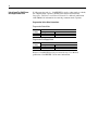
Table A PowerFlex 700S EN61800-3 EMC Compatibility
(1)
(1) External filters for First Environment installations and increasing motor cable lengths in Second Environment
installations are available. Roxburgh models KMFA (RF3 for UL installations) and MIF or Schaffner FN3258
and FN258 models are recommended. Refer to http://www.deltron-emcon.com and http://www.mtecorp.com
(USA) or http://www.schaffner.com, respectively.
Frame(s)
Second Environment First Environment Restricted Distribution
Restrict Motor Cable to 30 m (98 ft.) Restrict Motor Cable to 150 m (492 ft.)
Any Drive and Option Any Drive and Option External Filter Required
1 - 6 ✔✔✔

6
General Notes • If the adhesive label is removed from the top of the drive, the drive must
be installed in an enclosure with side openings less than 12.5 mm (0.5
in.) and top openings less than 1.0 mm (0.04 in.) to maintain compliance
with the LV Directive.
• The motor cable should be kept as short as possible in order to avoid
electromagnetic emission as well as capacitive currents.
• Use of line filters in ungrounded systems is not recommended.
• PowerFlex drives may cause radio frequency interference if used in a
residential or domestic environment. The installer is required to take
measures to prevent interference, in addition to the essential
requirements for CE compliance provided in this section, if necessary.
• Conformity of the drive with CE EMC requirements does not guarantee
an entire machine or installation complies with CE EMC requirements.
Many factors can influence total machine/installation compliance.
• PowerFlex drives can generate conducted low frequency disturbances
(harmonic emissions) on the AC supply system.
• More information regarding harmonic emissions can be found in the
PowerFlex 700S Phase II Control - Reference Manual, publication
PFLEX-RM003.
• When operated on a public supply system, it is the responsibility of the
installer or user to ensure, by consultation with the distribution network
operator and Rockwell Automation, if necessary, that applicable
requirements have been met.

7
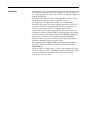
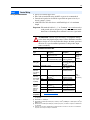
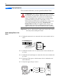
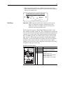
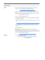
Minimum Mounting Clearances
Figure 1 Minimum Mounting Clearance Requirements
Operating Temperatures PowerFlex 700S drives are designed to operate in a surrounding air
temperature range of 0
° to 40° C. To operate the drive in installations with
surrounding air temperature between 41
° and 50° C, remove the adhesive
label affixed to the top of the drive enclosure.
Important: Removing the adhesive label from the drive changes the NEMA
enclosure rating from Type 1 to Open type.
Step 2 Mount the Drive
101.6mm
(4.0 in.)
101.6mm
(4.0 in.)
50.8mm (2.0 in.)
50.8mm (2.0 in.)
101.6mm
(4.0 in.)
101.6mm
(4.0 in.)
With Adhesive Label
(see below)
No Adhesive Label
(see below)

8
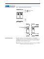
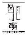
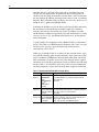
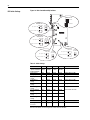
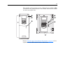
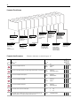
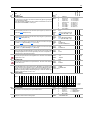
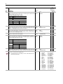
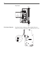
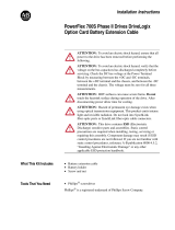
Dimensions
Table B PowerFlex 700S Frames
Figure 2 PowerFlex 700S Frame 1-3 (Frame 1 Shown)
Frame
AC Input DC Input
208 240 380 . . . 400V 480V 600V 690V 540V 650V
ND HP HD HP ND HP HD HP ND kW HD kW ND HP HD HP ND HP HD HP ND HP HD HP ND HP HD HP ND HP HD HP
1 0.75 0.37 1.0 0.75 0.75 0.55 1 0.75 1 0.5 – – – – – –
1.5 0.75 2.0 1.5 1.5 0.75 2 1.5 2 1 – – – – – –
2.2 1.5 3.0 2.0 2.2 1.5 3 2 3 2 – – – – – –
4.0 2.2 5.0 3.0 4.0 2.2 5 3 5 3 – – – – – –
5.5 4.0 7.5 5.0 5.5 4.0 7.5 5 7.5 5 – – – – – –
– – – – 7.5 5.5 10 7.5 10 7.5 – – – – – –
– – – – 11 7.5 15 10 15 10 – – – – – –
2 7.5 5.5 10 7.5 15 11 20 15 20 15 – – – – – –
– – 18.5 15 25 20 25 20 – – – – – –
3 11 7.5 15 10 22 18.5 30 25 30 25 – – – – – –
15 11 20 15 30 22 40 30 40 30 – – – – – –
– – – – 37 30 50 40 50 40 – – – – – –
4 18.5152520453760 506050– – – – – –
22 18.5 30 25 – – – – – – – – – –
5 30 22 40 30 55 45 75 60 75 60 75 55 55 45 75 60
30 30 50 40 55 45 100 75 100 75 90 75 55 45 75 60
– – – – – – – – – – – – 55 45 100 75
– – – – – – – – – – – – 55 45 100 75
6 45 37 60 50 90 75 125 100 125 100 110 90 90 75 125 100
55 45 75 60 110 90 150 125 150 125 132 110 90 75 125 100
66 55 100 75 132 110 200 150 – – – – 110 90 150 125
– – – – – – – – – – – – 110 90 150 125
– – – – – – – – – – – – 132 110 200 150
– – – – – – – – – – – – 132 110 200 150
Frame
(1)
(1) Refer to Ta b l e B for frame information.
Slim
A
Expanded
AA
BCDE
Weight
(2)
kg (lbs.)
(2) Weights include HIM, DriveLogix controller with ControlNet daughtercard, Hi-Resolution Encoder Option, and 20-COMM-C ControlNet adapter.
Drive Drive & Packaging
1 135.0 (5.31) 166.9 (6.57) 336.0 (13.23) 200.0 (7.87) 105.0 (4.13) 320.0 (12.60) 7.03 (15.5) 9.98 (22)
2 222.0 (8.74) 253.9 (9.99) 342.5 (13.48) 200.0 (7.87) 192.0 (7.56) 320.0 (12.60) 12.52 (27.6) 15.20 (33.5)
3 222.0 (8.74) 253.9 (9.99) 517.5 (20.37) 200.0 (7.87) 192.0 (7.56) 500.0 (19.69) 18.55 (40.9) 22.68 (50)
Dimensions are in millimeters and (inches)
A
AA
D
15.0
(0.59)
5.5 (0.22)
5.8
(0.23) dia.
B
E
8.0
(0.31)
312
(12.28)
C

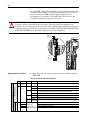
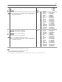
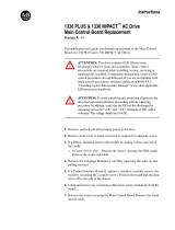
9
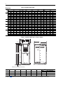
Figure 3 PowerFlex 700S Bottom View Dimensions, Frame1-3
133.3
(5.25)
187.6
(7.39)
25.5
(1.00)
70.0 (2.76)
43.0 (1.69)
96.0 (3.78)
75.9 (2.99)
108.5 (4.27)
67.5 (2.66)
47.5 (1.87)
87.5 (3.44)
22.2 (0.87) Dia.
3 Places
28.6 (1.13) Dia.
185.1
(7.29)
162.3
(6.39)
39.3 (1.55)
57.2 (2.25)
72.7 (2.86)
106.0 (4.17)
139.4 (5.49)
177.4 (6.98)
167.5 (6.59)
156.9 (6.18)
150.9
(5.94)
184.8
(7.28)
157.5
(6.20)
112.1
(4.41)
22.4 (0.88) Dia.
2 Places
28.7 (1.13) Dia.
3 Places
Frame 1 Frame 2
Dimensions are in millimeters and (inches)
Frame 3 - All Drives, except 50 HP, 480 V (37 kW, 400V) Frame 3 - 50 HP, 480V (37 kW, 400V) Normal Duty
66.0 (2.60)
94.7 (3.73)
105.3 (4.15)
97.0 (3.82)
137.2 (5.40)
187.0 (7.36)
22.7 (0.89)
29.0 (1.14)
127.7
(5.03)
151.1
(5.95)
160.1
(6.30)
165.1
(6.50)
184.5
(7.26)
22.2 (0.87) Dia.
28.7 (1.13) Dia.
2 Places
37.3 (1.47) Dia.
2 Places
66.0 (2.60)
94.7 (3.73)
105.3 (4.15)
130.0 (5.12)
186.0 (7.32)
22.7 (0.89)
29.0 (1.14)
127.7
(5.03)
160.1
(6.30)
165.1
(6.50)
184.5
(7.26)
28.7 (1.13) Dia.
2 Places
46.7 (1.84) Dia.
2 Places
34.9 (1.37) Dia.
2 Places
Vent Plate

10
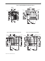
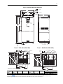
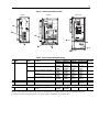
Figure 4 PowerFlex 700S Frame 4 Dimensions
Frame
(1)
(1) Refer to the Tab le B table for frame information.
Slim
A (Max.)
Expanded
AA B C (Max.) DE
Weight
(2)
kg (lbs.)
(2) Weights include HIM, DriveLogix controller with ControlNet daughtercard, Hi-Resolution Encoder Option, and 20-COMM-C ControlNet adapter.
Drive Drive & Packaging
4 220.0 (8.66) 251.9 (9.92) 758.8 (29.87) 201.7 (7.94) 192.0 (7.56) 738.2 (29.06) 24.49 (54.0) 29.03 (64.0)
Dimensions are in millimeters and (inches)
C
E
8.0
(0.31)
B
8.0 (0.31)
3 Places
A
D
13.0 (0.55)
Lifting Holes
4 Places
7.0 (0.27) 2 Places
15.1 (0.59)
S
AA
312
(12.28)
54.1 (2.13) Dia.
2 Places
47.0 (1.85) Dia.
2 Places
28.7 (1.13) Dia.
2 Places
26.8 (1.06)
36.8 (1.45)
50.7 (2.00)
141.9
(5.59)
105.1
(4.14)
157.9
(6.21)
177.9
(7.00)
189.7
(7.47)
22.2 (0.87) Dia.
63.8 (2.51)
112.0 (4.41)
180.0 (7.09)
65.3 (2.57)
76.0 (2.99)

11
Figure 5 PowerFlex 700S Frame 5 Dimensions
Frame
(1)
(1) Refer to the Tab l e B table for frame information.
Slim
A (Max.)
Expanded
AA B C (Max.) DE
Weight
(2)
kg (lbs.)
(2) Weights include HIM, DriveLogix controller with ControlNet daughtercard, Hi-Resolution Encoder Option, and 20-COMM-C ControlNet adapter.
Drive Drive & Packaging
5 308.0 (12.16) 339.9 (13.38) 644.5 (25.37)
(3)
(3) When using the supplied junction box (100 HP drives Only), add an additional 45.1 mm (1.78 in.) to this dimension.
275.4 (10.84) 225.0 (8.86) 625.0 (24.61) 37.19 (82.0) 42.18 (93.0)
Frame 5 - 75 HP, 480 V (55kW, 400V)
Frame 5 - 100 HP, 480 V (55kW, 400V)
Dimensions are in millimeters and (inches)
HOT surfaces can cause severe burns
CAUTION
E
12.5
(0.49)
6.5 (0.26)
B
D
A
259.1 (10.20)
Detail
15.0 (0.59)
6.5 (0.26)
37.6
(1.48)
C
Lifting Holes - 4 Places
12.7 (0.50) Dia.
312
(12.28)
S
AA
96.0
(3.78)
159.5
(6.28)
184.0
(7.24)
220.0
(8.66)
229.5
(9.04)
241.9
(9.52)
45.0 (1.77)
85.0 (3.35)
93.2 (3.67)
104.0 (4.09)
150.0 (5.91)
215.0 (8.46)
255.0 (10.04)
28.0 (1.10)
22.2 (0.87) Dia.
2 Places
62.7 (2.47) Dia.
2 Places
34.9 (1.37) Dia.
2 Places
96.0
(3.78)
153.5
(6.04)
184.3
(7.26)
188.5
(7.42)
223.5
(8.80)
241.9
(9.52)
44.0 (1.73)
66.4 (2.61)
31.9 (1.26)
42.6 (1.68)
128.0 (5.04)
232.3 (9.15)
28.0 (1.10)
22.2 (0.87) Dia.
2 Places
62.7 (2.47) Dia.
2 Places
Removable
Junction Box
34.9 (1.37) Dia.

12
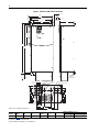
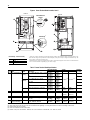
Figure 6 PowerFlex 700S Frame 6 Dimensions
Frame
(1)
(1) Refer to the Ta b l e B table for frame information.
Slim
A (Max.)
Expanded
AA B C (Max.) DE
Approx. Weight
(2)
kg (lbs.)
(2) Weights include HIM and Standard I/O.
Drive Drive & Packaging
6 403.9 (15.90) 435.8 (17.16) 850.0 (33.46) 275.5 (10.85) 300.0 (11.81) 825.0 (32.48) 71.44 (157.5)
(3)
(3) Add an additional 3.6 kg (8.00 lbs.) for 200 HP drives.
91.85 (202.5)
116.6
(4.59)
148.5
(5.85)
222.3
(8.75)
242.0
(9.53)
219.0
(8.62)
185.4
(7.30)
151.8
(5.98)
52.1 (2.05)
69.1 (2.72)
130.1 (5.12)
280.1 (11.03)
330.1 (13.00)
230.1 (9.06)
47.1 (1.85)
45.6 (1.80)
56.2 (2.21)
Removable Junction Box
22.2 (0.87) Dia.
4 Places
62.7 (2.47) Dia.
3 Places
34.9 (1.37) Dia.
3 Places
Dimensions are in millimeters and (inches)
E
13.5 (0.53)
126.3
(4.97)
8.5 (0.33)
B
Lifting Holes
4 Places
12.7 (0.50) Dia.
D
C
A
360.6 (14.20)
Detail
18.0 (0.71)
8.5 (0.33)
49.6
(1.95)
AA
312
(12.28)

13
Wire Recommendations Since most start-up difficulties are the result of incorrect wiring, take every
precaution to assure the wiring is correct. Read and understand all items in
this section before beginning installation.
Power Cable Types Acceptable for 200-600 Volt Installations
General
A variety of cable types are acceptable for drive installations. For many
installations, unshielded cable is adequate, provided it can be separated
from sensitive circuits. As an approximate guide, allow a spacing of 0.3
meters (1 foot) for every 10 meters (32.8 feet) of length. In all cases, long
parallel runs must be avoided. Do not use cable with an insulation thickness
less than or equal to 15 mils (0.4mm/0.015 in.). Use tinned copper wire
only. Wire gauge requirements and recommendations are based on 75° C.
Do not reduce wire gauge when using higher temperature wire.
Unshielded
THHN, THWN or similar wire is acceptable for drive installation in dry
environments provided adequate free air space and/or conduit fill rates
limits are provided. Do not use THHN or similarly coated wire in wet
areas. Any wire chosen must have a minimum insulation thickness of 15
Mils and should not have large variations in insulation concentricity.
Shielded/Armored Cable
Shielded cable contains all of the general benefits of multi-conductor cable
with the added benefit of a copper braided shield that can contain much of
the noise generated by a typical AC Drive. Strong consideration for shielded
cable should be given in installations with sensitive equipment such as
weigh scales, capacitive proximity switches and other devices that may be
affected by electrical noise in the distribution system. Applications with
large numbers of drives in a similar location, imposed EMC regulations or a
high degree of communications/networking are also good candidates for
shielded cable.
Step 3 Power Wiring
!
ATTENTION: The following information is merely a guide for
proper installation. The Allen-Bradley Company cannot assume
responsibility for the compliance or the noncompliance to any
code, national, local or otherwise for the proper installation of this
drive or associated equipment. A hazard of personal injury and/or
equipment damage exists if codes are ignored during installation.
!
ATTENTION: National Codes and standards (NEC, VDE, BSI
etc.) and local codes outline provisions for safely installing
electrical equipment. Installation must comply with
specifications regarding wire types, conductor sizes, branch
circuit protection and disconnect devices. Failure to do so may
result in personal injury and/or equipment damage.

14
Shielded cable may also help reduce shaft voltage and induced bearing
currents for some applications. In addition, the increased impedance of
shielded cable may help extend the distance the motor can be located from
the drive without the addition of motor protective devices such as terminator
networks. Refer to Reflected Wave in Wiring and Grounding Guidelines for
PWM AC Drives, publication DRIVES-IN001.
Consideration should be given to all of the general specifications dictated by
the environment of the installation, including temperature, flexibility,
moisture characteristics and chemical resistance. In addition, a braided
shield should be included and specified by the cable manufacturer as having
coverage of at least 75%. An additional foil shield can be greatly improve
noise containment.
A good example of recommended cable is Belden® 295xx (xx determines
gauge). This cable has 4 XLPE insulated conductors with a 100% coverage
foil and an 85% coverage copper braided shield (with drain wire)
surrounded by a PVC jacket.
Other types of shielded cable are available, but the selection of these types
may limit the allowable cable length. Particularly, some of the newer cables
twist 4 conductors of THHN wire and wrap them tightly with a foil shield.
This construction can greatly increase the cable charging current required
and reduce the overall drive performance. Unless specified in the individual
distance tables as tested with the drive, these cables are not recommended
and their performance against the lead length limits supplied is not known.
Table C Recommended Shielded Wire for Power Wiring
Location Rating/Type Description
Standard
(Option 1)
600V, 90° C (194°F)
XHHW2/RHW-2
Anixter
B209500-B209507,
Belden
®
29501-29507, or
equivalent
Four tinned copper conductors with XLPE insulation.
Copper braid/aluminum foil combination shield and tinned
copper drain wire.
PVC jacket.
Standard
(Option 2)
Tray rated 600V, 90° C
(194° F) RHH/RHW-2
Anixter OLF-7xxxxx or
equivalent
Three tinned copper conductors with XLPE insulation.
5 mil single helical copper tape (25% overlap min.) with three
bare copper grounds in contact with shield.
PVC jacket.
Class I & II;
Division I & II
Tray rated 600V, 90° C
(194° F) RHH/RHW-2
Anixter 7V-7xxxx-3G
or equivalent
Three bare copper conductors with XLPE insulation and
impervious corrugated continuously welded aluminum armor.
Black sunlight resistant PVC jacket overall.
Three copper grounds on #10 AWG and smaller.

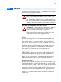
15
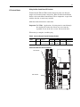
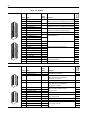
Figure 7 Power Terminal Block Location
Table D Power Terminal Block Specifications
BR1 BR2 DC+ DC- U/T1 V/T2 W/T3 R/L1 S/L2 T/L3
Optional
Communications
Module
PE B
PE A
75C Cu Wire
3 AWG [25MM
2
] Max.
16 IN. LBS.
1.8 N-M
} TORQUE
WIRE
STRIP
CONTROL
POWER
AUX IN
+ –
SHLD
SHLD
PE
75C Cu Wire
6 AWG [10MM
2
] Max.
BR1 BR2
12 IN. LBS.
1.4 N-M
} TORQUE
BR1 B
SHLD SHLD
V/T2 W/T3 PE R/L1 S/L2 T/L3
AUX IN+ AUX OUT–
Optional
Communications
Module
75C Cu Wire
6 AWG [10MM
2
] Max.
12 IN. LBS.
1.4 N-M
} TORQUE
WIRE
STRIP
CONTROL
POWER
BR1
BR2
DC+
DC–
PE
U/T1
V/T2
W/T3
R/L1
S/L2
T/L3
Use 75C Wire Only
#10-#14 AWG
Torque to 7 in-lbs
!
DANGER
➊
➋
➊
➋
➊
➋
Frame 1
Frame 2
Frame 3 & 4
➌
➌
➌
PE
/
No. Name Frame Description
Wire Size Range
(1)
Torque
Terminal
Bolt Size
(2)
Maximum Minimum Maximum Recommended
➊
Power Terminal Block 1 Input power and motor connections 4.0 mm
2
(10 AWG)
0.5 mm
2
(22 AWG)
1.7 N-m
(15 lb.-in.)
0.8 N-m
(7 lb.-in.)
—
2 Input power and motor connections 10.0 mm
2
(6 AWG)
0.8 mm
2
(18 AWG)
1.7 N-m
(15 lb.-in.)
1.4 N-m
(12 lb.-in.)
—
3 Input power and motor connections 25.0 mm
2
(3 AWG)
2.5 mm
2
(14 AWG)
3.6 N-m
(32 lb.-in.)
1.8 N-m
(16 lb.-in.)
—
BR1, BR2 10.0 mm
2
(6 AWG)
0.8 mm
2
(18 AWG)
1.7 N-m
(15 lb.-in.)
1.4 N-m
(12 lb.-in.)
—
4 Input power and motor connections 35.0 mm
2
(1/0 AWG)
10 mm
2
(8 AWG)
4.0 N-m
(24 lb.-in.)
4.0 N-m
(24 lb.-in.)
—
➋
SHLD Terminal 1-4 Terminating point for wiring shields — — 1.6 N-m
(14 lb.-in.)
1.6 N-m
(14 lb.-in.)
—
➌
AUX Terminal Block 1-4 Auxiliary Control Voltage
(3)
PS+, PS-
1.5 mm
2
(16 AWG)
0.2 mm
2
(24 AWG)
—— —
(1) Maximum/minimum sizes that the terminal block will accept - these are not recommendations.
(2) Apply counter torque to the nut on the other side of terminations when tightening or loosening the terminal bolt in order to avoid damage to the terminal.
(3) External control power: UL Installation - 300V DC, ±10%, Non UL Installation - 270-600V DC, ±10%. Frame 1-6, 100 W

16
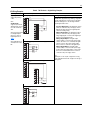
Figure 8 Power Terminal Block Location, Cont’d
Table E Power Terminal Block Specifications
WIRE RANGE: 14-1/0 AWG (2.5-35 MM
2
)
TORQUE: 32 IN-LB (3.6 N-M)
STRIP LENGTH: 0.67 IN (17 MM)
USE 75 C CU WIRE ONLY
POWER TERMINAL RATINGS
WIRE RANGE: 6-1/0 AWG (16-35 MM
2
)
TORQUE: 44 IN-LB (5 N-M)
STRIP LENGTH: 0.83 IN (21 MM)
GROUND TERMINAL RATINGS (PE)
300 VDC EXT PWR SPLY TERM (PS+, PS-)
WIRE RANGE: 22-10 AWG (0.5-4 MM
2
)
TORQUE: 5.3 IN-LB (0.6 N-M)
STRIP LENGTH: 0.35 IN (9 MM)
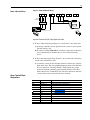
17
21
INPUT ACOUTPUT
Optional
Communications
Module
9
480 Volt Tap
600 Volt Tap
690 Volt Tap
400 Volt Tap
Three-Phase
Single-Phase
Spare
Spare
Line Type
(default)
Fan VA Rating - Common Bus Only
Frame Fan Voltage (120V or 240V)
5 100 VA
6 138 VA
Frame 5
➊
➋
➌
Phase Selection
Jumper
Fan Voltage
1
➍
1
Frame 5 & 6 utilize a transformer to match the input line voltage to the internal fan voltage. If you line voltage is dif-
ferent then the voltage class specified on the drive nameplate, it may be necessary to change the transformer taps. The
taps are shown in the inserts of frames 5 & 6.
Common Bus drives require user supplied 120V or 240V to power the cooling fans. Power source is connected between
“0V AC” and the terminal corresponding to your source voltage.
Optional
Communications
Module
L2L1T3T2T1 L3
INPUTOUTPUT
USE 75 C
COPPER WIRE
ONLY
TORQUE
52 IN-LB
(6 N-M)
BR2
PS+
PS–
BR1 DC+ DC–
USE 75 C COPPER WIRE ONLY, TORQUE 52 IN-LB (6 N-M)
22-10
AWG
5.3 IN-LB
(0.6 N-M)
WIRE STRIP
➋
➌
➊
Frame 6
➍
No. Name Frame Description
Wire Size Range
(1)
Torque
Terminal
Bolt Size
(2)
Maximum Minimum Maximum Recommended
➊
Power Terminal Block 5
(75 HP)
(3)
R, S, T, BR1, BR2, DC+, DC-, U, V and
W
50.0 mm
2
(1/0 AWG)
2.5 mm
2
(14 AWG)
See Note
(4)
See Note
(4)
—
PE
50.0 mm
2
(1/0 AWG)
4.0 mm
2
(12 AWG)
—
5
(100 HP)
(3)
R, S, T, DC+, DC-, U, V and W
70.0 mm
2
(2/0 AWG)
16.0 mm
2
(6 AWG)
—
BR1, BR2
50.0 mm
2
(1/0 AWG)
2.5 mm
2
(14 AWG)
—
PE
50.0 mm
2
(1/0 AWG)
4.0 mm
2
(12 AWG)
—
6 Input power and motor connections
120.0 mm
2
(4/0 AWG)
2.5 mm
2
(14 AWG)
6 N-m
(52 lb.-in.)
6 N-m
(52 lb.-in.)
—
➋
SHLD Terminal 5-6 Terminating point for wiring shields — — 1.6 N-m
(14 lb.-in.)
1.6 N-m
(14 lb.-in.)
—
➌
AUX Terminal Block 5-6 Auxiliary Control Voltage
(5)
PS+, PS-
4.0 mm
2
(10 AWG)
0.5 mm
2
(22 AWG)
0.6 N-m
(5.3 lb.-in.)
0.6 N-m
(5.3 lb.-in.)
—
➍
Fan Terminal Block
(Common Bus Only)
5-6 User Supplied Fan Voltage
0V AC, 120V AC, 240V AC
4.0 mm
2
(10 AWG)
0.5 mm
2
(22 AWG)
0.6 N-m
(5.3 lb.-in.)
0.6 N-m
(5.3 lb.-in.)
—
(1) Maximum/minimum sizes that the terminal block will accept - these are not recommendations.
(2) Apply counter torque to the nut on the other side of terminations when tightening or loosening the terminal bolt in order to avoid damage to the terminal.
(3) Not all terminals present on all drives.
(4) Refer to the terminal block label inside the drive.
(5) External control power: UL Installation - 300V DC, ±10%, Non UL Installation - 270-600V DC, ±10%. Frame 1-6, 100 W

17
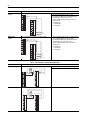
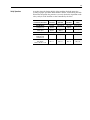
Power & Ground Wiring
Figure 9 Power and Ground Wiring
Important Common Bus (DC Input) Application Notes
1. If drives without internal precharge are used (Frames 5 & 6 only), then:
a) precharge capability must be provided in the system to guard against
possible damage, and
b) disconnect switches Must Not be used between the input of the drive
and a common DC bus without the use of an external precharge
device.
2. If drives with internal precharge (Frames 1-6) are used with a disconnect
switch to the common bus, then:
a) an auxiliary contact on the disconnect must be connected to a digital
input of the drive. The corresponding input (parameter 361-366) must
be set to option 30, “Precharge Enable.” This provides the proper
precharge interlock, guarding against possible damage to the drive
when connected to a common DC bus. The drive must have firmware
version 2.002 or above (Standard & Vector Control).
Power Terminal Block
Designations
PE
R
(L1)
S
(L2)
T
(L3)
U
(T1)
V
(T2)
W
(T3)
DC
+
DC
–
Required
Input Fusing
Required Branch
Circuit Disconnect
BR1 BR2
Terminal Description Notes
BR1 DC Brake (+) Dynamic Brake Resistor Connection (+)
BR2 DC Brake (–) Dynamic Brake Resistor Connection (–)
DC+ DC Bus (+) DC Input Power or Dynamic Brake Chopper
DC– DC Bus (–) DC Input Power or Dynamic Brake Chopper
PE PE Ground Refer to Figure 9 on page 17
for location on Frame 3 drives
Motor Ground Refer to Figure 7 on page 15
for location on Frame 3 drives
U U (T1) To motor
V V (T2) To motor
W W (T3) To motor
R R (L1) AC Line Input Power
S S (L2) AC Line Input Power
T T (L3) AC Line Input Power

18
Using PowerFlex 700S Drives
with Regen Power Units
If a Regenerative unit (i.e., 1336 REGEN) is used as a bus supply or a brake,
the common mode capacitors should be disconnected. Refer to the
PowerFlex 700S Drives with Phase II Control User Manual, publication
20D-UM006, for information on removing common mode capacitors.
Regenerative Unit to Drive Connections
Regenerative Brake Mode
Regenerative Bus Supply Mode
Refer to 1336 REGEN Line Regeneration Package User Manual,
publication 1336-REGEN-5.0, for more information.
Frame(s)
Terminals
1336 Regen PowerFlex 700S
1 - 4 DC+ & DC- BR1 & DC-
5 & 6 DC+ & DC- DC+ & DC-
Frame(s)
Terminals
1336 Regen PowerFlex 700S
1 - 4 DC+ & DC- DC+ & DC-
5 & 6 DC+ & DC- DC+ & DC- of the Common Bus Drives

19
Wiring Recommendations • Always use tinned copper wire.
• Wire with an insulation rating of 600V or greater is recommended.
• Control and signal wires should be separated from power wires by at
least 0.3 meters (1 foot).
• 4100CCF3 Flex I/O cable for use with DriveLogix is 3 ft. maximum
length
.
Important: I/O terminals labeled “(–)” or “Common” are not referenced to
earth ground and are designed to greatly reduce common mode
interference. Grounding these terminals can cause signal noise.
Table F Recommended Control Wire
Step 4 Control Wiring
!
ATTENTION: Hazard of personal injury or equipment damage
exists when using bipolar input sources. Noise and drift in sensitive
input circuits can cause unpredictable changes in motor speed and
direction. Use speed command parameters to help reduce input
source sensitivity.
Type Wire Type(s) Description
Insulation
Rating
Digital I/O Un-shielded Per US NEC or applicable
national or local code
–
300V, 60
o
C
(140
o
F),
Minimum
Shielded Multi-conductor shielded cable
such as Belden 8770(or equiv.)
0.750 mm
2
(18AWG), 3
conductor, shielded.
Standard
Analog I/O
Belden 8760/9460 (or equiv.) 0.750 mm
2
(18AWG),
twisted pair, 100% shield
with drain
(5)
.
(5) If the wires are short and contained within a cabinet which has no sensitive circuits, the use of shielded wire
may not be necessary, but is always recommended.
300V,
75-90
ºC
(167-194
ºF)
Remote Pot Belden 8770(or equiv.) 0.750 mm
2
(18AWG), 3
cond., shielded
Encoder/
Pulse I/O
Less 30.5 m
(100 ft.)
Combined: Belden 9730 (or equivalent)
(1)
(1) Belden 9730 is 3 individually shielded pairs (2 channel plus power). If 3 channel is required, use Belden 9728
(or equivalent).
0.196 mm
2
(24AWG),
individually shielded.
Encoder/
Pulse I/O
30.5 m (100
ft.) to 152.4
m (500 ft.)
Signal: Belden 9730/9728 (or
equivalent)
(1)
0.196 mm
2
(24AWG),
individually shielded.
Power: Belden 8790
(2)
(2) Belden 8790 is 1 shielded pair.
0.750 mm
2
(18AWG)
Combined: Belden 9892
(3)
(3) Belden 9892 is 3 individually shielded pairs (3 channel), 0.33 mm
2
(22 AWG) plus 1 shielded pair 0.5 mm
2
(20
AWG) for power.
0.330 mm
2
or 0.500 mm
2
(3)
Encoder/
Pulse I/O
152.4 m
(500 ft.) to
259.1 m
(850 ft.)
Signal: Belden 9730/9728 (or
equivalent)
(1)
0.196 mm
2
(24AWG),
individually shielded.
Power: Belden 8790
(2)
0.750 mm
2
(18AWG)
Combined: Belden 9773/9774 (or
equivalent)
(4)
(4) Belden 9773 is 3 individually shielded pairs (2 channel plus power). If 3 channel is required, use Belden 9774
(or equivalent).
0.750 mm
2
(18AWG),
individually shielded pair.
EMC
Compliance
Refer to EMC Instructions
on page 5 for details.

20
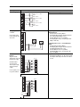
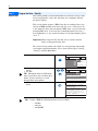
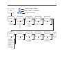
DIP Switch Settings
Figure 10 Main Control Board Dip Switches
Table G Switch Settings
Please note there are two separate values for an encoder.
S1
12
FRONT
TOP VIEW
SIDE VIEW
Up = Open = Off
Down = Closed = On
SWITCH S5
FRONT
TOP VIEW
SIDE VIEW
Up = Open = Off
Down = Closed = On
SWITCH S2
12
34
12
FRONT
TOP VIEW
SIDE VIEW
Up = Open = Off
Down = Closed = On
SWITCH S3
12
FRONT
TOP VIEW
SIDE VIEW
Up = Open = Off
Down = Closed = On
SWITCH S4
= HW Enable
= No HW Enable
JUMPER P22
12
34
12
34
Function Switch Open Closed Default Notes
Configuring Digital
Input 6 for Hardware
Enable (HW Enbl)
P22
Jumper
pin 2-4
HW Enbl
pin 1-3
No Enbl
pin 2-4
HW Enbl
No Jmpr = HW Enbl
Analog Input 1 S5-2 Voltage Current Voltage Change with Power Off
Analog Input 2 S5-1 Voltage Current Voltage Change with Power Off
Digital Inputs 4-6
Voltage
S4-1,2 115V AC 24V DC 24V DC Change with Power Off
Digital Input 1
Voltage
S3-1 24V DC 12V DC 24V DC Change with Power Off
Digital Input 2
Voltage
S3-2 24V DC 12V DC 24V DC Change with Power Off
Encoder Supply
Voltage
S2-4 12V DC 5V DC 12V DC Change with Power Off
Set all switches the same
Encoder Signal A
Voltage
S2-1 12V DC 5V DC 12V DC
Encoder Signal B
Voltage
S2-2 12V DC 5V DC 12V DC
Encoder Signal Z
Voltage
S2-3 12V DC 5V DC 12V DC
Function Switch Up Center Down Notes
DriveLogix
Processor
S1 Prog Remote Run Processor Mode
Page is loading ...
Page is loading ...
Page is loading ...
Page is loading ...
Page is loading ...
Page is loading ...
Page is loading ...
Page is loading ...
Page is loading ...
Page is loading ...
Page is loading ...
Page is loading ...
Page is loading ...
Page is loading ...
Page is loading ...
Page is loading ...
Page is loading ...
Page is loading ...
Page is loading ...
Page is loading ...
Page is loading ...
Page is loading ...
Page is loading ...
Page is loading ...
-
 1
1
-
 2
2
-
 3
3
-
 4
4
-
 5
5
-
 6
6
-
 7
7
-
 8
8
-
 9
9
-
 10
10
-
 11
11
-
 12
12
-
 13
13
-
 14
14
-
 15
15
-
 16
16
-
 17
17
-
 18
18
-
 19
19
-
 20
20
-
 21
21
-
 22
22
-
 23
23
-
 24
24
-
 25
25
-
 26
26
-
 27
27
-
 28
28
-
 29
29
-
 30
30
-
 31
31
-
 32
32
-
 33
33
-
 34
34
-
 35
35
-
 36
36
-
 37
37
-
 38
38
-
 39
39
-
 40
40
-
 41
41
-
 42
42
-
 43
43
-
 44
44


Allen-Bradley PowerFlex 700S Quick start guide
- Category
- Power adapters & inverters
- Type
- Quick start guide
Ask a question and I''ll find the answer in the document
Finding information in a document is now easier with AI
Related papers
-
Allen-Bradley PowerFlex 70 User manual
-
Allen-Bradley PowerFlex 700S Quick start guide
-
-
-
-
-
-
-
-
Other documents
-
 Rockwell Automation PowerFlex 700S Programming Manual
-
 Rockwell Automation PowerFlex 700S Installation Instructions Manual
-
Rockwell PowerFlex 700H Programming Manual
-
 DIODE LED 12mm Tape Light Terminal Block Connector Installation guide
-
 Rockwell Automation PowerFlex 700S Reference guide
-
 Rockwell Automation PowerFlex 700S Reference guide
-
 Rockwell Automation PowerFlex 700S Migration Manual
-
Rockwell Automation Allen-Bradley PowerFlex 700S 20DB022 Installation Instructions Manual
-
 Rockwell Automation 1336 PLUS Operating instructions
-
Alliance Laundry Systems Washer 1336 User manual


