Rockwell Automation 1336 PLUS Operating instructions
- Type
- Operating instructions

Instructions
1336 PLUS & 1336 IMPACT
™
AC Drive
Main Control Board Replacement
Frames A - H
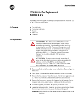
This publication will guide you through replacement of the Main Control
Board on 1336 PLUS and 1336 IMPACT AC Drives.
1. Remove and lock-out all incoming power to the drive.
2. Remove front cover or entire enclosure as required for adequate access.
3. If a HIM is installed, remove the module by sliding it down and out of
the cradle.
– A Frame Drives Only - Remove the screws securing the HIM cradle.
Remove the cradle and cable.
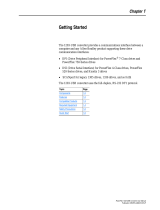
4. Remove the Language Module by carefully squeezing the sides-in, and
pulling outward.
5. If a Control Interface Board (L option) is installed, carefully remove the
board by loosening the 2 captive screws. Position the board and attached
wires off to the side of the chassis.
6. Label and remove any remaining cables/wires (note orientation) from the
board.
7. Remove the screws securing the Main Control Board. Remove the board
and set aside.
!
ATTENTION: This drive contains ESD (Electrostatic
Discharge) sensitive parts and assemblies. Static control
precautions are required when installing, testing, servicing or
repairing this assembly. Component damage may result if ESD
control procedures are not followed. If you are not familiar with
static control procedures, reference publication 8000-4.5.2,
“Guarding Against Electrostatic Damage” or any other applicable
ESD protection handbook.
!
ATTENTION: To avoid a shock hazard, assure that all power to the
drive has been removed before proceeding with the following
procedure. In addition, verify that the DC bus has discharged by
measuring across the “+DC” and “–DC” terminals of TB1 with a
voltmeter. The voltage should be 0.0VDC.

2 1336 PLUS & 1336 IMPACT
™
AC Drive Main Control Board Replacement
8. Install the replacement Main Control Board. Re-assemble components in
reverse order. If a Control Interface Board (L option) is
not being used,
verify that the jumpers are correctly inserted (see the drive User Manual for
details).
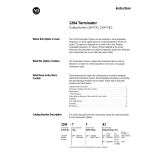
Important: If your drive is a 1336 IMPACT (Frames B-H), attach the
supplied label to the chassis in the area shown below.
Important: When replacing connectors, it is essential that correct
alignment is verified. Particular attention should be paid to
ribbon cable connectors. Misalignment of connectors could
result in damage to the drive.
!
ATTENTION: Replace any guards previously removed before
applying power to the drive. Failure to replace guards may result
in death or serious injury.
LANGUAGE MODULE
ALLEN-BRADLEY
LANGUAGE MODULE
ALLEN-BRADLEY
JOG
ESC
SEL
JOG
ESC
SEL
Frames A1 - A4
All Other Frames
Control Interface
(L Option) Board
Control Interface
(L Option) Board
Language Module
Jumpers
Language Module
DANGER
!!
Risk of electric shock and death.
Disconnect power, wait 5 minutes and
verify DC bus voltage before servicing.
Follow instructions in manual before use.
Earth ground required.
1336 IMPACT Drives
Attach label to chassis
above Main Control Board
1
336 IMPACT is a trademark of of Rockwell Automation, Inc.
Publication 1336 PLUS-5.67 – January, 2005 P/N 74103-909 (03)
Supersedes May, 1997 Copyright © 2005 Rockwell Automation, Inc. All rights reserved. Printed in USA.
-
 1
1
-
 2
2


Rockwell Automation 1336 PLUS Operating instructions
- Type
- Operating instructions
Ask a question and I''ll find the answer in the document
Finding information in a document is now easier with AI
Related papers
-
 Rockwell Automation Allen-Bradley Kinetix 6000 User manual
-
Allen-Bradley 1203-SSS User manual
-
 Rockwell Automation Allen-Bradley PowerFlex 700 Drive Frame 9 Installation Instructions Manual
-
 Rockwell Automation 1336 PLUS Operating instructions
-
Rockwell Automation Allen-Bradley PowerFlex 700S 20DB022 Installation Instructions Manual
-
 Rockwell Automation Allen-Bradley 1336 PLUS II Operating instructions
-
 Rockwell Automation PowerFlex 1203-USB User manual
-
 Rockwell Automation Allen-Bradley 1204 Series Instructions Manual
-
 Rockwell Automation PowerFlex 70 Maintenance Schedule
-
 Rockwell Automation Allen-Bradley PowerFlex 750 Series User manual


Other documents
-
-
-
-
Allen-Bradley PowerFlex 700S Selection Manual
-
-
-
-
-
-