Page is loading ...

Installation Instructions
Original Instructions
PowerFlex DC Field Controller Overvoltage Protection Device
Catalog Numbers 23P-FCOVPD-B-FA, 23P-FCOVPD-B-FB, 23P-FCOVPD-D-FA, 23P-FCOVPD-D-FB, 23P-FC-RB100, 23P-FC-RB200, 23P-FC-RB300, 23P-FC-RB400,
23P-FC-RB500
The overvoltage protection device (voltage clamp) helps to provide protection against overvoltage for the PowerFlex® DC field controller when
used with a highly inductive load. An overvoltage can occur when the AC supply voltage is turned off before the field controller is disabled. The
resulting overvoltage can damage the field controller.
The voltage clamp (cat. no. 23P-FCOVPD-x-Fx) is composed of a pair of Silicon Controlled Rectifier (SCR) modules and a circuit board. The
circuit board detects the load voltage level. When a potentially damaging voltage level is detected, the voltage clamp activates the appropriate SCR,
based on the direct of current flow. The SCRs conduct the excess current and allow the resistance in the motor field to gradually decay. The voltage
clamp must not be used to discharge inductive loads routinely. The voltage clamp requires approximately 30 minutes to dissipate the energy from an
overvoltage condition before power can be reapplied to the device.
A dampening resistor (RB) must be installed in combination with the voltage clamp. The dampening resistor is required to dampen the overvoltage
that results from undershooting holding current when the voltage clamp SCR stops conduction. Dampening resistor kits (cat. no. 23P-FC-RBn00)
must be purchased separately. See Dampening Resistor on page 3
for details.
The voltage clamp enclosure is rated IP20 and the power terminals are rated IP00. The dampening resistor terminals are rated IP00. Therefore,
these devices must be enclosed in a protective enclosure or appropriate guards must be provided to help protect against an electric shock and/or
burn hazard.
Topic Page
Product Advisories 2
Required Tools and Hardware 2
System Wiring Diagram 2
Dampening Resistor 3
Optional External Discharge Resistor 3
Voltage Clamp Thermostat 4
Voltage Clamp Nameplate Data 4
Product Dimensions and Weights 5
Minimum Mounting Clearances 8
Install the Voltage Clamp and Dampening Resistor 9
Additional Resources 11

2 Rockwell Automation Publication 23PFC-IN002A-EN-P - November 2018
PowerFlex DC Field Controller Overvoltage Protection Device
Product Advisories
Required Tools and Hardware
This table provides a list of customer-supplied tools and hardware that is required to install the voltage clamp.
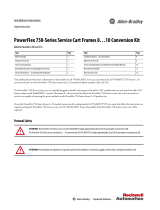
System Wiring Diagram
This diagram represents the recommended wiring configuration for a PowerFlex DC field controller, voltage clamp, required dampening resistor
(RB), and optional discharge resistor (RD).
Qualified Personnel
ATTENTION: Only qualified personnel familiar with DC drives, field controllers, motors and associated machinery should plan or implement the installation,
startup, and subsequent maintenance of the system. Failure to comply can result in personal injury and/or equipment damage.
Personal Safety
ATTENTION: To avoid an electric shock hazard, verify that all power to the connected devices has been removed before you begin installation.
ATTENTION: To avoid an electric shock hazard, the installer must provide guarding to shield exposed electrical equipment against accidental contact. Exposed
electrical components that carry potentially hazardous voltages are identified in this manual. When installing this equipment, consider the design and
placement of guarding to help prevent personal injury or equipment damage.
BURN HAZARD: Hot surfaces can cause severe burns. The dampening resistor assembly becomes hot during operation. To avoid a burn hazard, the installer
must provide guarding to shield exposed electrical equipment against accidental contact. After operation, allow time for the resistor assembly surfaces to cool
before you start maintenance.
Tools Hardware Hardware
Nut driver or torque wrench (10 mm, 13 mm, 15 mm).
M6 screws (8) for voltage clamp and dampening
resistor mounting.
M6 bolts and washers (2) for device cat. no. 23P-FCOVPD-B-FA and
23P-FCOVPD-D-FA power terminals (C, D).
Flat-nose and hexalobular screwdriver (T30).
M8 bolt and washer for voltage clamp ground (PE)
terminal.
M10 bolts and washers (2) for device cat. no. 23P-FCOVPD-B-FB and
23P-FCOVPD-D-FB power terminals (C, D).
U
V
W
C
D
PowerFlex DC
Field Controller
PE
RB
Voltage Clamp
C
D
RD
PE
L
RL
Load

Rockwell Automation Publication 23PFC-IN002A-EN-P - November 2018 3
PowerFlex DC Field Controller Overvoltage Protection Device
Dampening Resistor
A dampening resistor (RB) must be installed with the voltage clamp to dampen the overvoltage that results from undershooting holding current
when the SCR stops conduction. Purchase and install the appropriate resistor kit that is listed in the Dampening Resistor (RB) Kits table, or use the
sizing information to install a customer-supplied resistor.
Dampening Resistor Sizing Calculations
The value of resistor RB is determined by the 500 mA SCR holding current at the rectified voltage value. The dielectric strength of resistor RB is at
least double the rectified voltage value and its power loss is two to three times (for margin) the power dissipation that is calculated, considering the
rectified nominal voltage of the load.
Size a customer-supplied discharge resistor (RB) as follows:
RB value = 1.35 * V_line / 500 mA
RB dielectric strength ≥ 2 * 1.35 * V_line
RB power = 2 * (V_load)
2
/ RB
The available dampening resistor kits are shown in the Dampening Resistor (RB) Kits table. The resistor kits are sized with the value of resistor RB
as a function of V_line with a typical inductive load that is connected to the PowerFlex DC field controller. For most applications, the typical DC
output voltage is approximately 1.08 * V_line. By using the typical DC output voltage value as a guideline, the power dissipation value can be forced
to be a function of the AC input line voltage. Size a dampening resistor (RB) where V_load = 1.08 * V_line:
RB value = 1.35 V_line / 500 mA
RB dielectric strength ≥ 2 * 1.35 * V_line
RB power = 2 * (1.08 * V_line)
2
/ RB
(RB power = 2 increases the power dissipation margin.)
Optional External Discharge Resistor
An external discharge resistor (RD) must be installed to reduce the load current discharge time if the load τ is greater than the rated operation time,
as calculated in the Calculate the Average Power Dissipation Value for Resistor RD section on page 4. The time constant for the load is calculated
as:
τ = L / R, where L is the load inductance and R is the internal resistance of the load
The addition of resistor RD decreases the discharge time constant: τ = L /(R + RD)
Optional External Discharge Resistor Calculations
Calculate the Resistance Value of Resistor RD
To calculate the resistance value of resistor RD, the inductance and resistance of the existing load must be known. The desired time constant of the
“updated circuit” is expressed as:
τ = L / (R + RD)
Solve for RD.
Dampening Resistor (RB) Kits
Field Controller AC Input Voltage Range
(Vrms)
RB Resistor Value
Ohms
RB Resistor Size
Watts
RB Resistor Kit Cat. No.
(1)
(1) Resistor kits are IP00 / Open Type and must be installed in an enclosure.
60…100V 220 930 23P-FC-RB100
101…200V 390 930 23P-FC-RB200
201…300V 680 930 23P-FC-RB300
301…400V 1000 930 23P-FC-RB400
401…500V 1200 930 23P-FC-RB500

4 Rockwell Automation Publication 23PFC-IN002A-EN-P - November 2018
PowerFlex DC Field Controller Overvoltage Protection Device
Calculate the Peak Power Rating Value for Resistor RD
Calculate the peak power rating value for RD in watts, where the initial current is equal to the load current.
RD_peak_Power = (I_load)
2
* RD
Solve for RD_peak_Power.
Calculate the Average Power Dissipation Value for Resistor RD
Calculate the average power dissipation for resistor RD.
The initial current, Io, of the discharge circuit is the load current. The load actually consists of an inductance and a resistance in series (though the
only visible object is the load coil).
During the current discharge, the energy that is stored in the magnetic field of the load inductance is dissipated in the internal load resistance and
the external optional added resistor RD.
E = Energy, Joules
P = Power, Watts (Joules/Second)
L = Inductance, Henrys
R = Resistance, Ohms
I = Current, amps
Io = Initial Current, amps
τ = Circuit Time Constant L/R, Seconds
E = ½ * L_load * Io
2
(The initial value of the energy stored load inductance)
τ = L / (RD + R_load)
P_rd = [E / 6 * τ] * [RD / (RD + R_load)]
P_rd = Average power dissipation of resistor RD over six time constants (discharge time of the circuit).
Solve for P_rd.
Voltage Clamp Thermostat
A thermal-trip interlock terminal block (TB1) is provided on the top of the voltage clamp. Use this terminal block to interlock the voltage clamp
with the field controller control circuit. The thermal trip circuit opens when the voltage clamp heat-sink temperature is too high. When the
thermostat is open, the field controller is disabled.
Voltage Clamp Nameplate Data
The voltage clamp contains a data nameplate label on the side of each module. This nameplate identifies the specific catalog number, serial number,
and applicable power data. Include this information when communicating with Rockwell Automation personnel about this product.
EXAMPLE ONLY
Cat No. 23P-FCOVPD-D-FA
UL Type OPEN/IP20
Rated Voltage : 600 VDC
Max rated current : 120A
MFD, in 2018 on week 20
2018 20
Product of Italy
Rockwell Automation, 1201 S. 2nd St., Milwaukee, WI 53204, USA
Serial Number:
J20A0001
*K20E0013*
IND. CONT.
LISTED
C
R
US
31KF
Series: A
25
Rated Operation Time : 60 sec Rated Recovery Time : 1800 sec

Rockwell Automation Publication 23PFC-IN002A-EN-P - November 2018 5
PowerFlex DC Field Controller Overvoltage Protection Device
Product Dimensions and Weights
These illustrations provide the approximate dimensions and weights for the voltage clamp and dampening resistor kits. Use these dimensions for
mounting these devices.
Voltage Clamp Catalog Numbers 23P-FCOVPD-B-FA and 23P-FCOVPD-D-FA
179.6 (7.1)
210 (8.3)
117 (4.6)
7 (0.3)
194 (7.6)
20
(0.8)
10
(0.4)
63.5
(2.5)
25
(1.0)
7 (0.27)
9 (0.35)
64
(2.52)
1.5
(0.06)
116
(4.56)
3 (0.12)
12.5 (0.5)
13
(0.5)
225 (8.9)
141 (5.6)
Dimensions are in millimeters and (inches)
Maximum weight 5.25 kg (11.6 lb)

6 Rockwell Automation Publication 23PFC-IN002A-EN-P - November 2018
PowerFlex DC Field Controller Overvoltage Protection Device
Voltage Clamp Catalog Numbers 23P-FCOVPD-B-FB and 23P-FCOVPD-D-FB
179.6 (7.1)
210 (8.3)
117 (4.6)
7 (0.3)
194 (7.6)
25
(1.0)
12.5
(0.5)
63.5
(2.5)
25
(1.0)
10.5 (0.4)
9 (0.35)
64
(2.52)
1.5
(0.06)
116
(4.56)
5 (0.2)
12.5 (0.5)
13
(0.5)
225 (8.9)
141 (5.6)
Dimensions are in millimeters and (inches)
Maximum weight 5.25 kg (11.6 lb)

Rockwell Automation Publication 23PFC-IN002A-EN-P - November 2018 7
PowerFlex DC Field Controller Overvoltage Protection Device
Dampening Resistor Dimensions
50 (2.0) 426 (16.8)
64 (2.5)
48 (1.9)
24 (0.9)
6.5 (0.3)
6.5 (0.26)
5.5 (0.2)
R7.0 (0.3)
102 (4.0)
124 (4.9)
115 (4.5)
120 (4.7)
526 (21.1)
502 (19.8)
(Name plate)
Dimensions are in millimeters and (inches)
Weight 3.9 kg (8.6 lb)

8 Rockwell Automation Publication 23PFC-IN002A-EN-P - November 2018
PowerFlex DC Field Controller Overvoltage Protection Device
Minimum Mounting Clearances
The minimum clearances that are specified in this section must be provided to help avoid device overheating.
Voltage Clamp Clearances
Minimum clearance requirements for the voltage clamp are intended to be from device to device. Other objects can occupy this space; however,
reduced airflow can cause the voltage clamp to overheat. Air circulation through the device must not be impeded. The voltage clamp assembly must
be mounted in a vertical orientation (as shown here).
Dampening Resistor Clearances
Minimum clearance requirements for the dampening resistor are intended to be from device to device. The resistor assembly can be mounted
horizontally, or vertically. When mounted vertically, the terminal block must be below the resistor assembly (as shown here).
≥ 50 mm
(2.0 in.)
≥ 10 mm
(0.4 in.)
≥ 150 mm (6.0 in.)
≥ 150 mm (6.0 in.)
≥ 10 mm
(0.4 in.)
≥ 200 mm (7.9 in.)
≥ 200 mm (7.9 in.)
≥ 200 mm
(7.9 in.)
≥ 200 mm
(7.9 in.)
(Name plate)
(Name plate)

Rockwell Automation Publication 23PFC-IN002A-EN-P - November 2018 9
PowerFlex DC Field Controller Overvoltage Protection Device
Install the Voltage Clamp and Dampening Resistor
Follow these steps to install the voltage clamp and dampening resistor with a PowerFlex DC field controller.
Remove Power from the PowerFlex DC Field Controller
• Remove and lockout all incoming power to the field controller and any connected devices.
Mount the Voltage Clamp
The voltage clamp maximum weight is 5.25 kg (11.6 lb). Follow the steps to mount the voltage clamp.
1. Mark and verify the hole pattern on the panel on which you intend to mount the voltage clamp. See page 5
or page 6 for dimensions.
2. Partially install the lower M6 mounting screws into the mounting panel.
3. Lift the voltage clamp onto the screws that are installed in the panel.
4. Install the remaining screws into the panel and tighten all hardware to 7 N•m (62 lb•in).
Mount the Dampening Resistor
The dampening resistor weighs 3.9 kg (8.6 lb). Follow the steps to mount the dampening resistor.
1. Mark and verify the hole pattern on the panel on which you intend to mount the dampening resistor. See page 7
for dimensions.
2. Partially install the four M6 mounting screws into the mounting panel.
3. Lift the dampening resistor assembly onto the screws that are installed in the panel.
4. Tighten all hardware to 7 N•m (62 lb•in).
ATTENTION: Remove power before making or breaking cable connections. When you remove or insert a cable connector with power applied, an electric arc can
occur. An electric arc can cause personal injury or property damage by:
• sending an erroneous signal to your system field devices, causing unintended machine motion
• causing an explosion in a hazardous environment
Electrical arcing causes excessive wear to contacts on both a module and its mating connector. Worn contacts can create electrical resistance.
IMPORTANT Mount the voltage clamp as close as possible to the PowerFlex DC field controller. The minimum clearances must be met (see Minimum Mounting
Clearances on page 8
for details).
L1
L2 L3
O
I

10 Rockwell Automation Publication 23PFC-IN002A-EN-P - November 2018
PowerFlex DC Field Controller Overvoltage Protection Device
Wire the Voltage Clamp
Use the information in this section and the System Wiring Diagram on page 2 to wire the power and ground (PE) connections on the voltage clamp.
Voltage Clamp Power, Ground, and Thermostat Terminal Identification
Wire the Dampening Resistor
Use the information in this table and the System Wiring Diagram on page 2 to wire the dampening resistor.
Voltage Clamp Power and Ground (PE) Terminal Specifications
Terminal Description Wire Size Cat. No. Terminal Bolt Size
Recommended
Torque
C, D DC Power connections
Same as the connected
PowerFlex DC field controller.
23P-FCOVPD-B-FA,
23P-FCOVPD-D-FA
M6 7 N•m (62 lb•in)
23P-FCOVPD-B-FB,
23P-FCOVPD-D-FB
M10 25 N•m (221.2 lb•in)
PE Safety ground All M8 15 N•m (132.7 lb•in)
Voltage Clamp Thermostat Terminal Block and Wire Specifications
Terminal
Wire Size
Recommended Torque
Flexible / Multi-core
(mm
2
)
AWG
1
0.14…1.5 26…14 0.5 N•m (4.4 lb•in)
2
Dampening Resistor Terminal Block and Wire Specifications
Terminals Description Wire Size Wire Strip Length
Minimum Wire Insulation
Rating
Recommended Terminal
Torque
Power connection from voltage clamp terminals C and D. 14 AWG 2.5 mm
2
12 mm (0.5 in.) 600V, 80 °C (176 °F)
1.5…1.8 N•m (0.6…0.7
lb•in)
C
D
PE
Thermostat Terminal
Block (TB1)

Rockwell Automation Publication 23PFC-IN002A-EN-P - November 2018 11
PowerFlex DC Field Controller Overvoltage Protection Device
Additional Resources
These documents contain additional information concerning related products from Rockwell Automation.
You can view or download publications at http://www.rockwellautomation.com/global/literature-library/overview.page
. To order paper copies of
technical documentation, contact your local Allen-Bradley distributor or Rockwell Automation sales representative.
Voltage Clamp Ratings
Cat. No. 23P-FCOVPD-B-FA 23P-FCOVPD-B-FB 23P-FCOVPD-D-FA 23P-FCOVPD-D-FB
Maximum rated supply system voltage (VAC) 200 200 500 500
Maximum rated load system current (A DC) 120 570 120 570
Thyristor module (or equivalent) SKKT132/16E MCC501-16io2 SKKT132/16E MCC501-16io2
Rated operation time (s) 60
Rated recovery time (s) 1800
Operation ambient temperature - °C (°F) 0…50 (32…122)
Transportation and storage temperature - °C (°F) -25…+55 (13…131)
Degree of protection IP20; except power terminals - IP00
Overvoltage category III
Pollution degree 2
Installation altitude above sea level (m) ≤ 1000
Thermal protection temperature threshold - °C (°F) 70 (158)
Thermal protection ratings (max.) 250V, 2 A
Weight - kg (lb) 3.7 (8.2) 5.25 (11.6) 3.7 (8.2) 5.25 (11.6)
Resource Description
PowerFlex DC Field Controller Installation Instructions, publication 23PFC-IN001
Provides installation instructions for the PowerFlex DC Field Controller.
PowerFlex DC Field Controller Programming Manual, publication 23PFC-PM001
Provides information on how to start up, program, and troubleshoot the PowerFlex DC Field
Controller.
PowerFlex DC Drive Technical Data, publication 20P-TD001
Provides detailed information on:
• Basic product selection
• Field controller specifications
• Option specifications
• Circuit protection
Industrial Automation Wiring and Grounding Guidelines, publication 1770-4.1
Provides general guidelines for installing a Rockwell Automation® industrial system.
Product Certifications website,
http://www.rockwellautomation.com/global/certification/overview.page
Provides declarations of conformity, certificates, and other certification details.

Allen-Bradley, PowerFlex, Rockwell Automation, and Rockwell Software are trademarks of Rockwell Automation, Inc.
Trademarks not belonging to Rockwell Automation are property of their respective companies.
Rockwell Otomasyon Ticaret A.Ş., Kar Plaza İş Merkezi E Blok Kat:6 34752 İçerenköy, İstanbul, Tel: +90 (216) 5698400
Rockwell Automation maintains current product environmental information on its website at
http://www.rockwellautomation.com/rockwellautomation/about-us/sustainability-ethics/product-environmental-compliance.page
.
1S7A92
Publication 23PFC-IN002A-EN-P - November 2018
Copyright © 2018 Rockwell Automation, Inc. All rights reserved. Printed in U.S.A.
At the end of its life, this equipment should be collected separately from any unsorted municipal waste.
Rockwell Automation Support
Use the following resources to access support information.
Documentation Feedback
Your comments will help us serve your documentation needs better. If you have any suggestions on how to improve this document, complete the
How Are We Doing? form at http://literature.rockwellautomation.com/idc/groups/literature/documents/du/ra-du002_-en-e.pdf
.
Technical Support Center
Knowledgebase Articles, How-to Videos, FAQs, Chat, User
Forums, and Product Notification Updates.
https://rockwellautomation.custhelp.com/
Local Technical Support Phone Numbers Locate the phone number for your country. http://www.rockwellautomation.com/global/support/get-support-now.page
Direct Dial Codes
Find the Direct Dial Code for your product. Use the code to
route your call directly to a technical support engineer.
http://www.rockwellautomation.com/global/support/direct-dial.page
Literature Library
Installation Instructions, Manuals, Brochures, and
Technical Data.
http://www.rockwellautomation.com/global/literature-library/overview.page
Product Compatibility and Download
Center (PCDC)
Get help determining how products interact, check
features and capabilities, and find associated firmware.
http://www.rockwellautomation.com/global/support/pcdc.page
/