Page is loading ...

PowerFlex Digital DC Drive
Catalog Numbers 20P, 23P
User Manual
Original Instructions

Important User Information
Read this document and the documents listed in the additional resources section about installation, configuration, and
operation of this equipment before you install, configure, operate, or maintain this product. Users are required to
familiarize themselves with installation and wiring instructions in addition to requirements of all applicable codes, laws,
and standards.
Activities including installation, adjustments, putting into service, use, assembly, disassembly, and maintenance are
required to be carried out by suitably trained personnel in accordance with applicable code of practice.
If this equipment is used in a manner not specified by the manufacturer, the protection provided by the equipment may
be impaired.
In no event will Rockwell Automation, Inc. be responsible or liable for indirect or consequential damages resulting from
the use or application of this equipment.
The examples and diagrams in this manual are included solely for illustrative purposes. Because of the many variables and
requirements associated with any particular installation, Rockwell Automation, Inc. cannot assume responsibility or
liability for actual use based on the examples and diagrams.
No patent liability is assumed by Rockwell Automation, Inc. with respect to use of information, circuits, equipment, or
software described in this manual.
Reproduction of the contents of this manual, in whole or in part, without written permission of Rockwell Automation,
Inc., is prohibited.
Throughout this manual, when necessary, we use notes to make you aware of safety considerations.
Labels may also be on or inside the equipment to provide specific precautions.
WARNING: Identifies information about practices or circumstances that can cause an explosion in a hazardous
environment, which may lead to personal injury or death, property damage, or economic loss.
ATTENTION: Identifies information about practices or circumstances that can lead to personal injury or death, property
damage, or economic loss. Attentions help you identify a hazard, avoid a hazard, and recognize the consequence.
IMPORTANT Identifies information that is critical for successful application and understanding of the product.
SHOCK HAZARD: Labels may be on or inside the equipment, for example, a drive or motor, to alert people that dangerous
voltage may be present.
BURN HAZARD: Labels may be on or inside the equipment, for example, a drive or motor, to alert people that surfaces may
reach dangerous temperatures.
ARC FLASH HAZARD: Labels may be on or inside the equipment, for example, a motor control center, to alert people to
potential Arc Flash. Arc Flash will cause severe injury or death. Wear proper Personal Protective Equipment (PPE). Follow ALL
Regulatory requirements for safe work practices and for Personal Protective Equipment (PPE).

Rockwell Automation Publication 20P-UM001M-EN-P - November 2017 3
Table of Contents
Preface
. . . . . . . . . . . . . . . . . . . . . . . . . . . . . . . . . . . . . . . . . . . . . . . . . . . . . . . . .9
Summary of Changes . . . . . . . . . . . . . . . . . . . . . . . . . . . . . . . . . . . . . . . . . . 10
Conventions. . . . . . . . . . . . . . . . . . . . . . . . . . . . . . . . . . . . . . . . . . . . . . . . . . 11
Drive Storage Conditions . . . . . . . . . . . . . . . . . . . . . . . . . . . . . . . . . . . . . . 11
Drive Nameplate Data. . . . . . . . . . . . . . . . . . . . . . . . . . . . . . . . . . . . . . . . . 12
Drive Series Letter . . . . . . . . . . . . . . . . . . . . . . . . . . . . . . . . . . . . . . . . . 12
Drive Frame Sizes . . . . . . . . . . . . . . . . . . . . . . . . . . . . . . . . . . . . . . . . . 12
Drive Firmware Revision . . . . . . . . . . . . . . . . . . . . . . . . . . . . . . . . . . . 12
Drive Specifications . . . . . . . . . . . . . . . . . . . . . . . . . . . . . . . . . . . . . . . . . . . 12
Standard Drive Catalog Number Explanation . . . . . . . . . . . . . . . . . . . 13
Standard Drive Catalog Number Explanation, Cont. . . . . . . . . . . . . . 14
Standalone-Alone Regulator Catalog Numbers . . . . . . . . . . . . . . . . . . 14
Additional Resources . . . . . . . . . . . . . . . . . . . . . . . . . . . . . . . . . . . . . . . . . . 15
Chapter 1
Installation and Wiring Product Advisories . . . . . . . . . . . . . . . . . . . . . . . . . . . . . . . . . . . . . . . . . . . . 18
Mount the Drive . . . . . . . . . . . . . . . . . . . . . . . . . . . . . . . . . . . . . . . . . . . . . . 19
Operating Conditions and Temperatures. . . . . . . . . . . . . . . . . . . . 19
Minimum Mounting Clearances. . . . . . . . . . . . . . . . . . . . . . . . . . . . 19
Maximum Surrounding Air Temperature Specifications . . . . . . 19
Approximate Drive Dimensions and Weights . . . . . . . . . . . . . . . . . . . 20
Lifting PowerFlex DC Drives . . . . . . . . . . . . . . . . . . . . . . . . . . . . . . . . . . 26
Mount Frame C and D Drives . . . . . . . . . . . . . . . . . . . . . . . . . . . . . . 26
Remove the Drive Covers . . . . . . . . . . . . . . . . . . . . . . . . . . . . . . . . . . . . . . 28
Frame A Drives. . . . . . . . . . . . . . . . . . . . . . . . . . . . . . . . . . . . . . . . . . . . 28
Frame B and C Drives. . . . . . . . . . . . . . . . . . . . . . . . . . . . . . . . . . . . . . 29
Frame D . . . . . . . . . . . . . . . . . . . . . . . . . . . . . . . . . . . . . . . . . . . . . . . . . . 30
Isolation Transformers / Line Reactors. . . . . . . . . . . . . . . . . . . . . . . . . . 30
Contactors . . . . . . . . . . . . . . . . . . . . . . . . . . . . . . . . . . . . . . . . . . . . . . . . . . . 31
AC Input Contactors . . . . . . . . . . . . . . . . . . . . . . . . . . . . . . . . . . . . . . 32
DC Output Contactors . . . . . . . . . . . . . . . . . . . . . . . . . . . . . . . . . . . . 32
Dynamic Brake Resistors . . . . . . . . . . . . . . . . . . . . . . . . . . . . . . . . . . . 32
General Grounding Requirements . . . . . . . . . . . . . . . . . . . . . . . . . . . . . . 33
Safety Ground (PE). . . . . . . . . . . . . . . . . . . . . . . . . . . . . . . . . . . . . . . . 34
Power Feeder. . . . . . . . . . . . . . . . . . . . . . . . . . . . . . . . . . . . . . . . . . . . . . 34
Encoder/Resolver Ground Connections. . . . . . . . . . . . . . . . . . . . . 34
Tachometer Ground Connections . . . . . . . . . . . . . . . . . . . . . . . . . . 34
Grounding for Installations in an Ungrounded or
High-Impedance, Neutral Ground, or System . . . . . . . . . . . . . . . . . . . 35
Power Distribution . . . . . . . . . . . . . . . . . . . . . . . . . . . . . . . . . . . . . . . . 35
CE Conformity . . . . . . . . . . . . . . . . . . . . . . . . . . . . . . . . . . . . . . . . . . . . . . . 40
Low Voltage Directive . . . . . . . . . . . . . . . . . . . . . . . . . . . . . . . . . . . . . 40
EMC Directive. . . . . . . . . . . . . . . . . . . . . . . . . . . . . . . . . . . . . . . . . . . . 40
General Considerations . . . . . . . . . . . . . . . . . . . . . . . . . . . . . . . . . . . . 40

4 Rockwell Automation Publication 20P-UM001M-EN-P - November 2017
Table of Contents
Installation Requirements Related to the Low
Voltage Directive . . . . . . . . . . . . . . . . . . . . . . . . . . . . . . . . . . . . . . . . . . 41
Installation Requirements Related to EN 61800-3 and
the EMC Directive . . . . . . . . . . . . . . . . . . . . . . . . . . . . . . . . . . . . . . . . 41
Pollution Degree Ratings According to EN 61800-5-1 . . . . . . . 42
Power Circuit Protection . . . . . . . . . . . . . . . . . . . . . . . . . . . . . . . . . . . . . . 43
Control Power Circuit Protection . . . . . . . . . . . . . . . . . . . . . . . . . . . . . . 43
Cable and Wiring Recommendations . . . . . . . . . . . . . . . . . . . . . . . . . . . 44
Power Wiring. . . . . . . . . . . . . . . . . . . . . . . . . . . . . . . . . . . . . . . . . . . . . . . . . 45
AC Input Voltages. . . . . . . . . . . . . . . . . . . . . . . . . . . . . . . . . . . . . . . . . 45
DC Output Voltages. . . . . . . . . . . . . . . . . . . . . . . . . . . . . . . . . . . . . . . 46
Typical Power Wiring Diagrams . . . . . . . . . . . . . . . . . . . . . . . . . . . . 46
Armature Converter Connections . . . . . . . . . . . . . . . . . . . . . . . . . . 51
Armature Voltage Feedback Connections . . . . . . . . . . . . . . . . . . . 54
Field Converter Connections. . . . . . . . . . . . . . . . . . . . . . . . . . . . . . . 57
Field Current Configuration . . . . . . . . . . . . . . . . . . . . . . . . . . . . . . . 61
Set DIP Switch S14 to the Correct Value . . . . . . . . . . . . . . . . . . . . 62
Relay Outputs. . . . . . . . . . . . . . . . . . . . . . . . . . . . . . . . . . . . . . . . . . . . . 64
Thermistors and Thermal Switches . . . . . . . . . . . . . . . . . . . . . . . . . 64
Control Circuit Input Power . . . . . . . . . . . . . . . . . . . . . . . . . . . . . . . 67
Frame C Heatsink Cooling Fan Specifications . . . . . . . . . . . . . . . 71
Frame D, Series B and C Heatsink Cooling Fan
Specifications . . . . . . . . . . . . . . . . . . . . . . . . . . . . . . . . . . . . . . . . . . . . . 73
Frame C and D Armature Fuse Signal Terminals . . . . . . . . . . . . . 75
DIP Switch and Jumper Settings. . . . . . . . . . . . . . . . . . . . . . . . . . . . . . . . 77
I/O Wiring . . . . . . . . . . . . . . . . . . . . . . . . . . . . . . . . . . . . . . . . . . . . . . . . . . . 82
I/O Signal and Control Wiring . . . . . . . . . . . . . . . . . . . . . . . . . . . . . 83
Digital Encoder Terminal Block . . . . . . . . . . . . . . . . . . . . . . . . . . . . 88
DC Analog Tachometer Terminal Block . . . . . . . . . . . . . . . . . . . . 90
Resolver Feedback Module . . . . . . . . . . . . . . . . . . . . . . . . . . . . . . . . . 90
I/O and Control Wire Routing. . . . . . . . . . . . . . . . . . . . . . . . . . . . . 91
Chapter 2
Drive Start Up Drive Start Up Checklist. . . . . . . . . . . . . . . . . . . . . . . . . . . . . . . . . . . . . . . 93
Before Applying Power to the Drive . . . . . . . . . . . . . . . . . . . . . . . . . . . . 94
Verify all Drive Configuration Settings . . . . . . . . . . . . . . . . . . . . . . 94
Verify the Power Wiring . . . . . . . . . . . . . . . . . . . . . . . . . . . . . . . . . . . 94
Verify the Control and I/O Wiring . . . . . . . . . . . . . . . . . . . . . . . . . 94
Apply Power to the Drive . . . . . . . . . . . . . . . . . . . . . . . . . . . . . . . . . . . . . . 95
Apply Voltage to the Control Circuits. . . . . . . . . . . . . . . . . . . . . . . 95
Verify the Control Voltages . . . . . . . . . . . . . . . . . . . . . . . . . . . . . . . . 96
Load the Default Settings . . . . . . . . . . . . . . . . . . . . . . . . . . . . . . . . . . 97
Configure the Most Commonly Used Parameters . . . . . . . . . . . . 97
Tune the Current Regulator. . . . . . . . . . . . . . . . . . . . . . . . . . . . . . . 102
Verify Motor Rotation and Run Feedback Polarity Checks. . . 104
Configure the Speed Feedback Parameters . . . . . . . . . . . . . . . . . . 107
Tune the Speed Regulator . . . . . . . . . . . . . . . . . . . . . . . . . . . . . . . . . 109

Rockwell Automation Publication 20P-UM001M-EN-P - November 2017 5
Table of Contents
Verify Speed Reference Settings and Drive Operation. . . . . . . . 111
Chapter 3
Programming and Parameters About Parameters . . . . . . . . . . . . . . . . . . . . . . . . . . . . . . . . . . . . . . . . . . . . 116
Parameters Table Example . . . . . . . . . . . . . . . . . . . . . . . . . . . . . . . . 117
How Parameters are Organized. . . . . . . . . . . . . . . . . . . . . . . . . . . . . . . . 118
File–Group–Parameter Order . . . . . . . . . . . . . . . . . . . . . . . . . . . . . 118
Numbered List View. . . . . . . . . . . . . . . . . . . . . . . . . . . . . . . . . . . . . . 118
Cross Reference Tables . . . . . . . . . . . . . . . . . . . . . . . . . . . . . . . . . . . 118
Basic Parameter View . . . . . . . . . . . . . . . . . . . . . . . . . . . . . . . . . . . . . 119
Advanced Parameter View . . . . . . . . . . . . . . . . . . . . . . . . . . . . . . . . 121
Monitor File . . . . . . . . . . . . . . . . . . . . . . . . . . . . . . . . . . . . . . . . . . . . . . . . . 126
Motor Control File. . . . . . . . . . . . . . . . . . . . . . . . . . . . . . . . . . . . . . . . . . . 131
Speed Command File. . . . . . . . . . . . . . . . . . . . . . . . . . . . . . . . . . . . . . . . . 148
Dynamic Control File . . . . . . . . . . . . . . . . . . . . . . . . . . . . . . . . . . . . . . . . 155
Applications File . . . . . . . . . . . . . . . . . . . . . . . . . . . . . . . . . . . . . . . . . . . . . 161
Utility File. . . . . . . . . . . . . . . . . . . . . . . . . . . . . . . . . . . . . . . . . . . . . . . . . . . 177
Communications File. . . . . . . . . . . . . . . . . . . . . . . . . . . . . . . . . . . . . . . . . 191
Input / Output File . . . . . . . . . . . . . . . . . . . . . . . . . . . . . . . . . . . . . . . . . . 195
Parameter Cross Reference – by Name . . . . . . . . . . . . . . . . . . . . . . . . . 207
Parameter Cross Reference – by Number. . . . . . . . . . . . . . . . . . . . . . . 213
Chapter 4
Troubleshooting Faults and Alarms . . . . . . . . . . . . . . . . . . . . . . . . . . . . . . . . . . . . . . . . . . . . 219
Drive Status . . . . . . . . . . . . . . . . . . . . . . . . . . . . . . . . . . . . . . . . . . . . . . . . . 220
HIM Indicators . . . . . . . . . . . . . . . . . . . . . . . . . . . . . . . . . . . . . . . . . . 221
Manually Clearing Faults . . . . . . . . . . . . . . . . . . . . . . . . . . . . . . . . . . . . . 221
Fault Descriptions. . . . . . . . . . . . . . . . . . . . . . . . . . . . . . . . . . . . . . . . . . . . 222
How to Clear an Alarm. . . . . . . . . . . . . . . . . . . . . . . . . . . . . . . . . . . . . . . 228
Alarm Descriptions. . . . . . . . . . . . . . . . . . . . . . . . . . . . . . . . . . . . . . . . . . . 228
Common Drive Symptoms and Corrective Actions . . . . . . . . . . . . . 231
Drive does not start . . . . . . . . . . . . . . . . . . . . . . . . . . . . . . . . . . . . . . 231
Drive starts but motor does not turn and no
armature current . . . . . . . . . . . . . . . . . . . . . . . . . . . . . . . . . . . . . . . . . 232
The motor does not reach commanded speed . . . . . . . . . . . . . . . 232
The motor is turning in the wrong direction . . . . . . . . . . . . . . . . 232
The motor reaches maximum speed immediately . . . . . . . . . . . 233
The motor speed cannot be controlled and the drive
does not stop . . . . . . . . . . . . . . . . . . . . . . . . . . . . . . . . . . . . . . . . . . . . 233
Testpoint Codes and Functions . . . . . . . . . . . . . . . . . . . . . . . . . . . . . . . 233

6 Rockwell Automation Publication 20P-UM001M-EN-P - November 2017
Table of Contents
Appendix A
Supplemental Drive Information Certifications and Specifications. . . . . . . . . . . . . . . . . . . . . . . . . . . . . . . 236
IP20 NEMA / UL Type Open Watts Loss . . . . . . . . . . . . . . . . . . . . . 236
Communication Configurations . . . . . . . . . . . . . . . . . . . . . . . . . . . . . . 240
Typical Programmable-Controller Configurations . . . . . . . . . . 240
Logic Command/Status Words. . . . . . . . . . . . . . . . . . . . . . . . . . . . 241
Drive Power Circuit Protection . . . . . . . . . . . . . . . . . . . . . . . . . . . . . . . 243
Frame A and B Fuse Information . . . . . . . . . . . . . . . . . . . . . . . . . . 243
Frame C and D Fuse Information. . . . . . . . . . . . . . . . . . . . . . . . . . 251
Control Power Circuit Protection Fuses . . . . . . . . . . . . . . . . . . . . . . . 259
Switching Power Supply Circuit Board Fuses . . . . . . . . . . . . . . . 259
Frame B Pulse Transformer Circuit Board Fuses . . . . . . . . . . . . 261
Frame C Transient Noise Filter Circuit Board Fuses. . . . . . . . . 262
Frame D Overvoltage Clipping Circuit Board Fuses . . . . . . . . . 263
AC Input Line Reactors and AC Input Contactors . . . . . . . . . . . . . 264
Isolation Transformers . . . . . . . . . . . . . . . . . . . . . . . . . . . . . . . . . . . . . . . 267
Dynamic Brake Resistor Kits and DC Output Contactors . . . . . . . 269
DC Contactor Crimp Lug Kit Specifications . . . . . . . . . . . . . . . . . . . 271
Alternate Dynamic Brake Resistor Kits and DC Output
Contactors . . . . . . . . . . . . . . . . . . . . . . . . . . . . . . . . . . . . . . . . . . . . . . . . . . 272
Alternate EMC Filters . . . . . . . . . . . . . . . . . . . . . . . . . . . . . . . . . . . . . . . . 273
Terminal Adapter Kits for Frame D Drives . . . . . . . . . . . . . . . . . . . . . 279
Appendix B
HIM Overview External and Internal Connections . . . . . . . . . . . . . . . . . . . . . . . . . . . . 281
LCD Display Elements . . . . . . . . . . . . . . . . . . . . . . . . . . . . . . . . . . . . . . . 282
ALT Functions . . . . . . . . . . . . . . . . . . . . . . . . . . . . . . . . . . . . . . . . . . . . . . 282
Using the S.M.A.R.T. List Screen . . . . . . . . . . . . . . . . . . . . . . . . . . 283
Menu Structure . . . . . . . . . . . . . . . . . . . . . . . . . . . . . . . . . . . . . . . . . . . . . . 284
Viewing and Editing Parameters . . . . . . . . . . . . . . . . . . . . . . . . . . . . . . 286
LCD HIM . . . . . . . . . . . . . . . . . . . . . . . . . . . . . . . . . . . . . . . . . . . . . . 286
Removing/Installing the HIM. . . . . . . . . . . . . . . . . . . . . . . . . . . . . . . . . 287
Appendix C
Application Notes Alpha Test Mode. . . . . . . . . . . . . . . . . . . . . . . . . . . . . . . . . . . . . . . . . . . . . 289
Alpha Test Setup and Operation . . . . . . . . . . . . . . . . . . . . . . . . . . 290
Analog Input Configuration . . . . . . . . . . . . . . . . . . . . . . . . . . . . . . . . . . 292
Example 1: . . . . . . . . . . . . . . . . . . . . . . . . . . . . . . . . . . . . . . . . . . . . . . . 292
Example 2: . . . . . . . . . . . . . . . . . . . . . . . . . . . . . . . . . . . . . . . . . . . . . . . 292
Analog-input Signal Comparison . . . . . . . . . . . . . . . . . . . . . . . . . . 293
Current / Speed Curve . . . . . . . . . . . . . . . . . . . . . . . . . . . . . . . . . . . . . . . 294
Drive Reference and Feedback Scaling . . . . . . . . . . . . . . . . . . . . . . . . . 296
Armature Voltage Feedback . . . . . . . . . . . . . . . . . . . . . . . . . . . . . . . 296
DC Analog Tachometer Feedback . . . . . . . . . . . . . . . . . . . . . . . . . 296
Encoder Feedback . . . . . . . . . . . . . . . . . . . . . . . . . . . . . . . . . . . . . . . . 297
Drive Reference and Feedback Scaling Examples . . . . . . . . . . . . 297

Rockwell Automation Publication 20P-UM001M-EN-P - November 2017 7
Table of Contents
Valid Speed Feedback Values . . . . . . . . . . . . . . . . . . . . . . . . . . . . . . 300
Droop Compensation . . . . . . . . . . . . . . . . . . . . . . . . . . . . . . . . . . . . . . . . 302
Field-weakening Mode Configuration (v1.006) . . . . . . . . . . . . . . . . . 302
Using a DC Contactor Only (Firmware v1.006 Only) . . . . . . . 303
Using a DC Contactor and a Dynamic Brake
(Firmware v1.006 Only) . . . . . . . . . . . . . . . . . . . . . . . . . . . . . . . . . . 303
Using an Inverting Fault Device Only (Firmware
v1.006 Only). . . . . . . . . . . . . . . . . . . . . . . . . . . . . . . . . . . . . . . . . . . . . 304
Using a DC Contactor and an Inverting Fault Device
(Firmware v1.006 Only) . . . . . . . . . . . . . . . . . . . . . . . . . . . . . . . . . . 304
Using a DC Contactor, a Dynamic Brake and an
Inverting Fault Device (Firmware v1.006 Only). . . . . . . . . . . . . 305
Lifting/Torque Proving. . . . . . . . . . . . . . . . . . . . . . . . . . . . . . . . . . . . . . . 306
Tuning The Motor For Torque Prove Applications . . . . . . . . . 308
Crane Setup with Encoder/Resolver Feedback . . . . . . . . . . . . . . 308
Crane Setup - Encoderless . . . . . . . . . . . . . . . . . . . . . . . . . . . . . . . . . 313
Manually Tuning the Speed Regulator for Firmware Revision
6.001 and Later . . . . . . . . . . . . . . . . . . . . . . . . . . . . . . . . . . . . . . . . . . . . . . 317
Multiple Motor Applications. . . . . . . . . . . . . . . . . . . . . . . . . . . . . . . . . . 319
Considerations for Multiple Motors Connected in Parallel. . . 319
Considerations for Multiple Motors Connected in Series . . . . 319
Parameter 21 [Min Firing Angle] Configuration . . . . . . . . . . . . . . . . 320
PID Function. . . . . . . . . . . . . . . . . . . . . . . . . . . . . . . . . . . . . . . . . . . . . . . . 321
Configure a Line Speed Signal . . . . . . . . . . . . . . . . . . . . . . . . . . . . . 321
Configure the Feedback Signal in the Follower
Drive/Drives . . . . . . . . . . . . . . . . . . . . . . . . . . . . . . . . . . . . . . . . . . . . . 323
Configure the Tension Set Point Signal in the
Follower Drive/Drives . . . . . . . . . . . . . . . . . . . . . . . . . . . . . . . . . . . . 324
Reference Control. . . . . . . . . . . . . . . . . . . . . . . . . . . . . . . . . . . . . . . . . . . . 325
“Auto” Speed Sources . . . . . . . . . . . . . . . . . . . . . . . . . . . . . . . . . . . . . 325
“Manual” Speed Sources . . . . . . . . . . . . . . . . . . . . . . . . . . . . . . . . . . 325
Speed Source Changes . . . . . . . . . . . . . . . . . . . . . . . . . . . . . . . . . . . . 326
Torque Reference Source. . . . . . . . . . . . . . . . . . . . . . . . . . . . . . . . . . 326
Auto/Manual Examples. . . . . . . . . . . . . . . . . . . . . . . . . . . . . . . . . . . 326
Resolver Cable Balance Tuning Test . . . . . . . . . . . . . . . . . . . . . . . . . . . 328
Performing the Cable Balance Tuning Test . . . . . . . . . . . . . . . . . 328
Resolver Type Selection. . . . . . . . . . . . . . . . . . . . . . . . . . . . . . . . . . . . . . . 329
Scale Blocks. . . . . . . . . . . . . . . . . . . . . . . . . . . . . . . . . . . . . . . . . . . . . . . . . . 330
Link Parameters Via the Scale Block Parameters. . . . . . . . . . . . . 331
SCR Diagnostic Tests . . . . . . . . . . . . . . . . . . . . . . . . . . . . . . . . . . . . . . . . 331
Open SCR Test . . . . . . . . . . . . . . . . . . . . . . . . . . . . . . . . . . . . . . . . . . 332
Shorted SCR Test . . . . . . . . . . . . . . . . . . . . . . . . . . . . . . . . . . . . . . . . 333
S
-curve Configuration . . . . . . . . . . . . . . . . . . . . . . . . . . . . . . . . . . . . . . . . 333
S-curve Acceleration Ramp Example:. . . . . . . . . . . . . . . . . . . . . . . 335
Speed Regulation Functions. . . . . . . . . . . . . . . . . . . . . . . . . . . . . . . . . . . 335
Adaptive Speed Regulator . . . . . . . . . . . . . . . . . . . . . . . . . . . . . . . . . 335
Speed Up Function . . . . . . . . . . . . . . . . . . . . . . . . . . . . . . . . . . . . . . . 338

8 Rockwell Automation Publication 20P-UM001M-EN-P - November 2017
Table of Contents
Speed Threshold Indicators . . . . . . . . . . . . . . . . . . . . . . . . . . . . . . . 339
Speed Zero Function. . . . . . . . . . . . . . . . . . . . . . . . . . . . . . . . . . . . . . 340
Speed Draw Function. . . . . . . . . . . . . . . . . . . . . . . . . . . . . . . . . . . . . 341
Speed / Torque Mode Selection . . . . . . . . . . . . . . . . . . . . . . . . . . . . . . . 342
Zero Torque Mode . . . . . . . . . . . . . . . . . . . . . . . . . . . . . . . . . . . . . . . 342
Speed Regulation Mode . . . . . . . . . . . . . . . . . . . . . . . . . . . . . . . . . . . 343
Torque Regulation Mode . . . . . . . . . . . . . . . . . . . . . . . . . . . . . . . . . 343
Speed Limited Adjustable Torque (SLAT) Min Mode
and SLAT Max Mode. . . . . . . . . . . . . . . . . . . . . . . . . . . . . . . . . . . . . 343
Sum Mode . . . . . . . . . . . . . . . . . . . . . . . . . . . . . . . . . . . . . . . . . . . . . . . 347
Start At Powerup. . . . . . . . . . . . . . . . . . . . . . . . . . . . . . . . . . . . . . . . . . . . . 348
Fine-Tuning the Regulators . . . . . . . . . . . . . . . . . . . . . . . . . . . . . . . . . . . 349
Manually Adjusting the Current Regulator Tune Settings. . . . 350
Fine-Tuning the Field Current Regulator. . . . . . . . . . . . . . . . . . . 352
Fine-Tuning the Speed Regulator . . . . . . . . . . . . . . . . . . . . . . . . . . 354
Fine-Tuning the Voltage Regulator in the Field Converter . . . 356
Tuning the Field Current Curve . . . . . . . . . . . . . . . . . . . . . . . . . . . 358
Appendix D
Control Block Diagrams Diagram Conventions . . . . . . . . . . . . . . . . . . . . . . . . . . . . . . . . . . . . 361
Appendix E
Installing a Communication
Adapter
Communication Adapter Kits. . . . . . . . . . . . . . . . . . . . . . . . . . . . . . . . . 385
What The Communication Adapter Kit Includes. . . . . . . . . . . . . . . 385
Tools That You Need . . . . . . . . . . . . . . . . . . . . . . . . . . . . . . . . . . . . . . . . 385
Safety Precautions . . . . . . . . . . . . . . . . . . . . . . . . . . . . . . . . . . . . . . . . . . . . 386
Installing the Communication Adapter Module in the Drive. . . . . 386
Frame A . . . . . . . . . . . . . . . . . . . . . . . . . . . . . . . . . . . . . . . . . . . . . . . . . 387
Frames B and C . . . . . . . . . . . . . . . . . . . . . . . . . . . . . . . . . . . . . . . . . . 388
Frame D . . . . . . . . . . . . . . . . . . . . . . . . . . . . . . . . . . . . . . . . . . . . . . . . . 389
Appendix F
Optional Analog and Digital I/O
Expansion Circuit Board
What This Option Board Provides . . . . . . . . . . . . . . . . . . . . . . . . . . . . 391
I/O Expansion Board Wiring . . . . . . . . . . . . . . . . . . . . . . . . . . . . . . . . . 391
Appendix G
Optional 115V AC to 24V DC I/O
Converter Circuit Board
What This Option Board Provides . . . . . . . . . . . . . . . . . . . . . . . . . . . . 393
I/O Converter Board Wiring. . . . . . . . . . . . . . . . . . . . . . . . . . . . . . . . . . 394
Appendix H
PowerFlex DC Standalone
Regulator Installation
Installation and Wiring Instructions . . . . . . . . . . . . . . . . . . . . . . . . . . . 397
Index
. . . . . . . . . . . . . . . . . . . . . . . . . . . . . . . . . . . . . . . . . . . . . . . . . . . . . . . . 399

Rockwell Automation Publication 20P-UM001M-EN-P - November 2017 9
Preface
The purpose of this manual is to provide you with the basic information
required to install, start-up, and troubleshoot the PowerFlex® DC drive. This
manual is intended for qualified personnel. You must be able to program and
operate DC drives. In addition, you must have an understanding of the
parameter settings and functions that are detailed in this manual.
For PowerFlex DC Stand-Alone Regulator (SAR) installations, see
Appendix H
beginning on page 397 for important installation and
configuration information.
This contents of this manual pertain to PowerFlex DC drive and PowerFlex
Standalone Regulator firmware revisions 1.006…7.001.
Topic Page
Summary of Changes 10
Conventions 11
Drive Storage Conditions 11
Drive Nameplate Data 12
Drive Specifications 12
Additional Resources 15
Standard Drive Catalog Number Explanation 13
Standalone-Alone Regulator Catalog Numbers 14
Additional Resources 15

10 Rockwell Automation Publication 20P-UM001M-EN-P - November 2017
Preface
Summary of Changes
This manual contains new and updated information.
Topic Page
Moved the product firmware revision information from the front cover to the Preface. 9
Moved the General Precautions section to Chapter 1 - Installation and Wiring. 18
Removed the Technical Support information from the Preface. See the back cover of
this manual for Rockwell Automation support information.
–
Updated the guidance on multiple motor applications. 17
Updated the weights for frame A drives. 20
Updated the Field Current Configuration section with information on configuring the
field current for an external, three-phase field and permanent magnet motor.
61
Updated the DIP switch S14 settings description in the Control Circuit Board Jumper
and DIP Switch Settings table.
78
Updated the Drive Start Up procedures to include configuration of the field current for
an external, three-phase field and permanent magnet motor use.
93
Add the new parameters to the Advanced Parameter View table. 121
Added the following new parameters to Chapter 3 - Programming and Parameters: –
Updated the description for Par 500 [Flux Ref Pct]. 129
Updated the description for Par 280 [Nom Mtr Fld Amps] to include details for
PowerFlex DC Field Controller applications.
132
Changed the maximum value for parameter 374 [Drv Fld Brdg Cur] from 80.00 to
570.00 Amps.
132
Added options 4…7 to parameter 469 [Field Mode Sel] for PowerFlex DC Field
Controller operating mode selections.
134
Changed the maximum value for parameter 1381 [Testpoint Sel] from 574 to 585. 183
Added option 26 “FC Fdbk” to the [Anlg Inx Sel] parameters (70, 75, and 80). 195
Changed option 24 “Field Ref” to “Flux Ref Pct” for the [Anlg Outx Sel] parameters
(66…69).
198
Added option 36 “Fld Cur Ref” to the [Anlg Outx Sel] parameters (66…69). 198
Added options 73 “Wired FC En”, 74 “Wired FC inv”, and 75 “Wired FC Act” to the
digital input parameters 133…144 [Digital Inx Sel].
199
Corrected the number for the Open SCR fault to 89. 223
Corrected the number for the Shorted SCR fault to 90. 224
Added the new SSC Error (20) fault. 225
Added the Open SCR alarm. 229
Added new codes 582…585 to the Testpoint Codes and Functions table. 233
Added the Multiple Motor Applications topic to Appendix C. 319
Added the Parameter 21 [Min Firing Angle] Configuration topic to Appendix C. 320
Removed Appendix I - History of Changes (obsoleted). –
Parameter Page
165 [Firing Angle] 129
21 [Min Firing Angle] 131
410 [Ext FC Curr Hyst] 133
411 [FC Lim Ramp] 137
412 [FC Lim Ramp Time] 137
409 [SSC Threshold] 186

Rockwell Automation Publication 20P-UM001M-EN-P - November 2017 11
Preface
Conventions
• To help differentiate parameter names and LCD display text from other
text, the following conventions are used:
– Parameter names appear in [brackets].
For example: [Armature Voltage].
– Display text appears in “quotes.” For example: “Enabled.”
Drive Storage Conditions
If it is necessary to store the drive for any length of time before installation,
follow these storage guidelines to provide satisfactory start-up operation and
retain warranty coverage:
• After receipt and inspection, repack the drive in its original shipping
container and store in a clean, dry place.
• Place where the ambient temperatures do not exceed -25°C (-13°F) or
55°C (131°F)
• Place where the range of relative air humidity does not exceed 5…95%.
• At an altitude of less than 3,000 meters (10,000 ft.) above sea level.

12 Rockwell Automation Publication 20P-UM001M-EN-P - November 2017
Preface
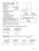
Drive Nameplate Data
The PowerFlex DC drive contains a data nameplate label on the side of each
drive. This nameplate identifies the specific model number, applicable AC
input power, and DC output power data. Include this information when
communicating with Rockwell Automation personnel about this product.
Drive Series Letter
Series B drives are identified as such on the data nameplate label. The drive
series letter is on the top, right side of the label.
Drive Frame Sizes
Similar PowerFlex DC drive ratings are grouped into frame sizes to make
ordering spare parts and drive dimensions simpler. The drive frame size is listed
just above the serial number on the data nameplate label. See the Standard
Drive Catalog Number Explanation on page 13
for a list of drive catalog
numbers and their respective frame sizes.
Drive Firmware Revision
The original firmware revision of the drive as shipped from the factory appears
on the data nameplate label just above the certifications. If the firmware
revision has been upgraded since the drive was shipped, you can view the
current revision on the HIM (if installed). See Diagnostics Menu on page 284
for details.
Drive Specifications
For drive specification information, see the PowerFlex Digital DC Drive,
Technical Data, 20P-TD001
.
EXAMPLE ONLY
20P41AD4P1RA0NNN
Made in Italy
Output: 500VDC 4.1A REGEN 2.0HP
1 Min Overload Amps
3 Sec Overload Amps
MFD. in 2XXX on MMM DD
Cat No.
Input: 460VAC 50/60 Hz 3.3A 3 Phase
UL Type OPEN/IP20
Original Firmware V. 1.001
Serial Number: A23E0042
Series: A
Frame: A
6.2
8.2
I/O: 24VDC (Standard)
Ind. Cont.
Listed
C
R
US
DC Field:
Input: 460VAC 50/60 Hz 10A max. 1 Phase
Output: 360VDC 10A max.
Regulator Power: 115/230VAC 50/60 Hz 1.0/0.5A 1 Phase
Eq. 31KF
N223
Certification Marks
Location.
See the data
nameplate label on
your drive for actual
agency certifications.
Drive frame size
Drive serial number
Drive series letter
Firmware revision

Rockwell Automation Publication 20P-UM001M-EN-P - November 2017 13
Preface
Standard Drive Catalog
Number Explanation
Position
1-3 4 5 6 7 8-10 11 12 13 14 15 16
20P 4 1 A D 4P1 R A 0 N N N
abcdef gh i jkl
a
Drive
Code Type
20P PowerFlex DC
b
Motor Operation
Code Type
2 Two Quadrant Operation
4 Four Quadrant Operation
c
Input Type
Code Type
1 6 Pulse
d
Enclosure
Code Enclosure Rating
Conform.
Coat
A IP20, NEMA/UL Type Open
e
Input Voltage
Code Voltage
B 230V AC
D 460V AC
E 600V AC
F 690V AC
f1
f2
Yes
Not available for 230V AC input drives.
Use this code for 400V AC input applications.
f3
f4
2
3
5
7.5
10
15
20
25
30
40
50
60
75
100
125
150
200
250
300
400
500
600
700
800
900
1.5
2.2
3.7
5.5
7.5
11
15
18.5
22
30
37
45
56
75
93
112
149
187
224
298
373
447
552
597
671
4.1
6
10
14
19
27
35
45
52
73
86
100
129
167
207
250
330
412
495
667
830
996
1162
1238
1494
A
A
A
A
A
A
A
A
A
A
A
A
A
B
B
B
B
B
C
C
D
D
D
D
D
10
10
10
10
10
10
10
10
10
14
14
14
14
20
20
20
20
20
20
20
40
40
70
70
70
Hp
Armature
Amps
Frame
Field
Amps
Code kW
460V, 60 Hz Input
4P1
6P0
010
014
019
027
035
045
052
073
086
100
129
167
207
250
330
412
495
667
830
996
1K1
1K3
1K4
1.5
2
3
5
7.5
10
15
20
25
30
40
50
60
75
100
125
150
200
250
300
1.2
1.5
2.2
3.7
5.5
7.5
11
15
18.5
22
30
37
45
56
75
93
112
149
186
224
7
9
12
20
29
38
55
73
93
110
146
180
218
265
360
434
521
700
875
1050
A
A
A
A
A
A
A
A
A
A
B
B
B
B
B
B
C
C
D
D
10
10
10
10
10
10
10
14
14
14
20
20
20
20
20
20
20
20
40
40
Hp
Armature
Amps
Frame
Field
Amps
Code kW
230V, 60 Hz Input
7P0
9P0
012
020
029
038
055
073
093
110
146
180
218
265
360
434
521
700
875
1K0
50
75
100
200
300
400
500
600
800
900
1000
1250
37
56
75
149
224
298
373
447
597
671
746
932
67.5
101.3
135
270
405
540
675
810
1080
1215
1350
1668
B
B
B
B
B
C
C
D
D
D
D
D
20
20
20
20
20
20
20
40
40
40
40
40
Hp
Armature
Amps
Frame
Field
Amps
Code kW
575V, 60 Hz Input
067
101
135
270
405
540
675
810
1K0
1K2
1K3
1K6
298
373
447
552
597
671
746
820
932
1044
Hp
Armature
Amps
Frame
Field
Amps
Code kW
690V, 60 Hz Input
452
565
678
791
904
1K0
1K1
1K2
1K4
1K5
400
500
600
700
800
900
1000
1100
1250
1400
452
565
678
791
904
1017
1130
1243
1413
1582
C
C
D
D
D
D
D
D
D
D
20
20
40
40
40
40
70
70
70
70

14 Rockwell Automation Publication 20P-UM001M-EN-P - November 2017
Preface
Standard Drive Catalog
Number Explanation, Cont.
Standalone-Alone Regulator
Catalog Numbers
Conformally coated circuit boards are provided with the following catalog
numbers.
Position
1-3 4 5 6 7 8-10 11 12 13 14 15 16
20P 4 1 A D 4P1 R A 0 N N N
abcdefghi jkl
g
Field Supply
Code Type
R Single-Phase Regulated
h
Packaging/Documentation
Code Shipping Carton User Manual
A Yes Yes
i
HIM
Code Operator Interface
0 Blank Cover
Standard - for user installed options, see
Human Interface and Wireless Interface
Modules on page 9.
j
I/O Options
Code Control
N
None (8 - 24V DC Digital Inputs,
4 Digital Outputs, 3 Analog Inputs,
and 2 Analog Outputs are Standard)
k
Communication Options
Code Description
N None
l
Cabinet Options
Code Type
N None
Standard - for user installed options, see
Communication Option Kits on page 10.
All I/O Options are purchased separately and
are user installed. See I/O Options on page 9.
230V / 460V AC Input Regulators 575V / 690V AC Input Regulators Field Amps
Cat. No. Cat. No.
23PMD4 23PMF4 40
23PMD7 23PMF7 70
23PAMP
(1)
23PAMP
(1)
(1)
(1) Gate Amplifier - used with all voltage classes of the Stand-Alone Regulator. The Stand-Alone Regulator and Gate Amplifier are
currently sold through Rockwell Automation Drive Systems only. Consult the factory for availability.

Rockwell Automation Publication 20P-UM001M-EN-P - November 2017 15
Preface
Additional Resources
These documents contain additional information concerning related products
from Rockwell Automation.
You can view or download publications at
http://www.rockwellautomation.com/global/literature-library/overview.page
.
To order paper copies of technical documentation, contact your local
Allen-Bradley distributor or Rockwell Automation sales representative.
Resource Description
PowerFlex Digital DC Drive and PowerFlex DC Field
Controller Technical Data, publication 20P-TD001
Provides detailed information on drive, field controller
and option specifications.
Preventive Maintenance of Industrial Control and Drive
System Equipment, publication DRIVES-TD001
Provides a checklist for performing preventive
maintenance.
PowerFlex Digital DC Drive - Frame A Hardware Service
Manual, publication 20P-TG001
Provides hardware test procedures and spare parts
replacement instructions for Frame A PowerFlex DC
drives and field controllers.
PowerFlex Digital DC Drive - Frame B Hardware Service
Manual, publication 20P-TG002
Provides hardware test procedures and spare parts
replacement instructions for Frame B PowerFlex DC
drives and field controllers.
PowerFlex Digital DC Drive - Frame C Hardware Service
Manual, publication 20P-TG003
Provides hardware test procedures and spare parts
replacement instructions for Frame C PowerFlex DC
drives and field controllers.
PowerFlex Digital DC Drive - Frame D Hardware Service
Manual, publication 20P-TG004
Provides hardware test procedures and spare parts
replacement instructions for Frame D PowerFlex DC
drives and field controllers.
Safety Guidelines for the Application, Installation, and
Maintenance of Solid-State Control, publication SGI-1.1
Provides general guidelines for the application,
installation, and maintenance of solid-state control in
the form of individual devices or packaged assemblies
that incorporate solid-state components.
Industrial Automation Wiring and Grounding Guidelines,
publication 1770-4.1
Provides general guidelines for installing a Rockwell
Automation industrial system.
Product Certifications website, http://
www.rockwellautomation.com/global/certification/
overview.page
Provides declarations of conformity, certificates, and
other certification details.

16 Rockwell Automation Publication 20P-UM001M-EN-P - November 2017
Preface
Notes:

Rockwell Automation Publication 20P-UM001M-EN-P - November 2017 17
Chapter 1
Installation and Wiring
This chapter provides information on how to install the PowerFlex® DC drive.
Most start-up difficulties are the result of incorrect wire connections. Take all
precautions to assure that wire connections are done as instructed. All items
must be read and understood before the actual installation begins.
For PowerFlex DC Stand-Alone Regulator (SAR) installations, see
Appendix H
beginning on page 397 for important installation and
configuration information. A 23PMDx catalog number on the data nameplate
on the drive identifies a SAR. (see Drive Nameplate Data on page 12
for
location).
The PowerFlex DC drive can be used in multiple motor applications. The
motors can be configured for parallel or series connections. See Multiple
Motor Applications on page 319
for installation and configuration guidance.
Topic Page Topic Page
Product Advisories 18 CE Conformity 40
Mount the Drive 19 Power Circuit Protection 43
Approximate Drive Dimensions and
Weights
20 Control Power Circuit Protection 43
Lifting PowerFlex DC Drives 26 Cable and Wiring Recommendations 44
Remove the Drive Covers 28 Power Wiring 45
Isolation Transformers / Line Reactors 30 DIP Switch and Jumper Settings 77
Contactors 31 I/O Wiring 82
General Grounding Requirements 33
IMPORTANT The PowerFlex DC drive is not designed for use with resistive or magnetic
loads.
IMPORTANT The recommended drive to motor horsepower ratio is 2:1.

18 Rockwell Automation Publication 20P-UM001M-EN-P - November 2017
Chapter 1 Installation and Wiring
Product Advisories
ATTENTION: The following information is merely a guide for proper
installation. Rockwell Automation cannot assume responsibility for the
compliance or the noncompliance to any code, national, local or otherwise for
the proper installation of this drive or associated equipment. If codes are
ignored during installation, a hazard of personal injury and equipment
damage exists.
ATTENTION: This drive contains ESD (Electrostatic Discharge) sensitive parts
and assemblies. Static control precautions are required when you install, test,
service, or repair this assembly. If ESD control procedures are not followed,
component damage can result. If you are not familiar with static control
procedures, see publication 8000-4.5.2, “Guarding Against Electrostatic
Damage” or any other applicable ESD protection handbook.
ATTENTION: An incorrectly applied or installed drive can result in component
damage or a reduction in product life. Installation or application errors, such
as, an undersized motor, incorrect or inadequate AC supply, or excessive air
temperatures around the drive can result in malfunction of the system.
ATTENTION: Allow only qualified personnel, familiar with DC drives and
associated machinery, to plan or implement the installation, start-up and
subsequent maintenance of the system. Failure to comply can result in
personal injury and equipment damage.
ATTENTION: An incorrectly applied or installed bypass system can result in
component damage or reduction in product life. The most common causes are:
• An AC line connection to the drive output or control terminals.
• Improper bypass or output circuits that are not Allen-Bradley approved.
• Output circuits that do not connect directly to the motor.
Contact Allen-Bradley for assistance with your application or installation.

Rockwell Automation Publication 20P-UM001M-EN-P - November 2017 19
Installation and Wiring Chapter 1
Mount the Drive
Operating Conditions and Temperatures
PowerFlex DC drives are designed to operate at 0…50 °C (32…122 °F)
surrounding air temperature without derating. The drive must be mounted in a
clean, dry location. Contaminants such as oils, corrosive vapors, and abrasive
debris must be kept out of the enclosure. NEMA / UL Type Open, IP20
enclosures are intended for indoor use primarily to provide a degree of
protection against contact with enclosed equipment. These enclosures offer no
protection against airborne contaminants.
Minimum Mounting Clearances
Minimum clearance requirements are intended to be from drive to drive.
Other objects can occupy this space; however, reduced airflow can cause
protection circuits to fault the drive. The drive must be mounted in a vertical
orientation as shown in Figure 1
and must not be mounted at an angle greater
than 30° from vertical. Intake air temperature must not exceed the product
specification.
Figure 1 - Drive Enclosure Minimum Mounting Clearances
Maximum Surrounding Air Temperature Specifications
• 0…50 °C (32…122 °F), typical
• De-rate 1.25% for every 1 °C (°F) over 50 °C (122 °F), to 55 °C (131 °F)
• Additional air cooling is required for temperatures above 55 °C (131 °F)
10 mm
10 mm
50 mm
(0.4 in.)
(0.4 in.) (2.0 in.)
10 mm
(0.4 in.)
150 mm (6.0 in.)
150 mm (6.0 in.)
150 mm (6.0 in.)
STS
PORT
MOD
NET A
NET B
STS
PORT
MOD
NET A
NET B
Airflow through the drive
must not be impeded.

20 Rockwell Automation Publication 20P-UM001M-EN-P - November 2017
Chapter 1 Installation and Wiring
Approximate Drive
Dimensions and Weights
The PowerFlex DC drive is available in a NEMA / UL Type Open, IP20
enclosure only. Follow all mounting clearances to provide proper drive
operation.
Figure 2 - Frame A Drive Dimensions
Table 1 - Frame A Weights
ATTENTION: Remove all loose packing materials, including the containers of
desiccants (if any), from the drive enclosure before you mount and energize
the drive.
A B C A1A2B1
mm (in.) mm (in.) mm (in.) mm (in.) mm (in.) mm (in.)
267 (10.5) 359 (14.0) 287 (11.3) 7 (0.3) 250 (9.8) 275 (10.8)
A
B
A2
B1
C
STS
PORT
MOD
NET A
NET B
A1
Drive Current Rating Code Drive Weight Drive and Packaging Weight
230V 460V kg (lb) kg (lb)
7P0 4P1 11.0 (24.25) 13.0 (28.7)
9P0 6P0
012 010
020 014
–019
029 027
038 035 11.5 (25.4) 13.5 (29.8)
055 045
–052
073 073 12.0 (26.5) 14.0 (30.9)
093 086
110 100
–129
/