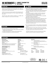
SIRO Series

HK Instruments SIRO Series User manual

  • Hello! I'm a chat assistant and I've read the HK Instruments Siro series air quality transmitter installation instructions. I'm familiar with its features, including its ability to measure CO2, VOC, and PM levels, as well as temperature and humidity. I'm ready to answer your questions about the device and its installation.
  • What are the typical applications for the Siro series devices?
    What measurements can the Siro series devices take?
    What is the CO2 measurement principle used by Siro?
Copyright HK Instruments 2022 www.hkinstruments. Installaon version 2.0 2022
INSTALLATION
INSTRUCTIONS
Indoor air quality transmitters
Siro series
READ THESE INSTRUCTIONS CAREFULLY BEFORE
ATTEMPTING TO INSTALL, OPERATE OR SERVICE THIS DEVICE.
• Failuretoobservesafetyinformaonandcomplywithinstrucons
canresultinPERSONALINJURY,DEATHAND/ORPROPERTY
DAMAGE.
• Toavoidelectricalshockordamagetoequipment,disconnect
powerbeforeinstallingorservicinganduseonlywiringwith
insulaonratedforfulldeviceoperangvoltage.
• Toavoidpotenalreand/orexplosiondonotuseinpotenally
ammableorexplosiveatmospheres.
• Retaintheseinstruconsforfuturereference.
• Thisproduct,wheninstalled,willbepartofanengineeredsystem
whosespecicaonsandperformancecharacteriscsarenot
designedorcontrolledbyHKInstruments.Reviewapplicaons
andnaonalandlocalcodestoassurethattheinstallaonwill
befunconalandsafe.Useonlyexperiencedandknowledgeable
technicianstoinstallthisdevice.
Thank you for choosing an HK Instruments Siro series indoor air
qualitytransmier.TheSiroseriestransmiersareintendedforuse
inbuildingautomaonsystemsintheHVAC/Rindustry.
Sirois anindoor air qualitytransmierwitha moderndesign.The
transmierisavailablewithseveraloponalairqualitysensors.The
modulardevicecanbeequippedwithCO2concentraonandVOC
(Volale Organic Compounds) measurements or alternavely PM
(ParculateMaer)measurementandinaddion temperatureand
humiditymeasurements.Itoerseasyinstallaonandadjustment,
severaldierentmodeloponsandvariousoutputsignalsthatare
congurableseparatelyforeachmeasurementparameter.
TheSiroseriesdevicesareavailablewithuserinterfacethatincludes
LCDdisplayandbuonsmakingtheconguraonofthedevicequick
andeasy.Anexternalconguraontoolisavailablefordeviceswith-
outuserinterface.SiroulizestheindustrystandardNDIRmeasure-
mentprinciplewithself-calibrangABClogicTM for CO2 measurement.
•PMconcentraontomeasuresthesizeandamountofparculates
intheindoorairforexampletoassesstheperformanceofairlters
•temperatureandhumidityinHVAC/Renvironment
SPECIFICATIONS
Performance
Measurement ranges:
CO2:  0–2000ppm/4002000ppm
 (selectableviajumper)
VOC:  CO₂eq:4002000ppm
 TVOCppm:0–30.0ppm
 TVOCµg/m3:0–10000µg/m3
 IAQindex:1–5(UBArang)
PM1/PM2.5/PM10: 0–50μg/m³/0–500μg/m³
 (selectableviajumper)
 IAQindex:1-5(WHOrang)
Temperature:  0...50°C
Relavehumidity: 0100%rH
Accuracy:
CO2:  ±43ppm+3%ofreading(typical),
 addional±60ppmforrstweeks
VOC*:  15%ofreading(typical)
*VOCsensoristunedfortypicalIAQMixof22VOCsas
denedbyMølhaveetal.(1997)
PM:
0…100µg/m3:
PM2.5:  ±15µg/m³(at25⁰C±5⁰C)
PM1/PM10*:  ±25µg/m³(at25⁰C±5⁰C)
100…1000µg/m3:
PM2.5:  ±15%(at25⁰C±5⁰C)
PM1/PM10*:  ±25%(at25⁰C±5⁰C)
*PM1andPM10valuesarecalculatedfromPM2.5
measurementreadingwiththedefaultparcledistribuon.
Temperature:  ±0.5⁰C(typicalat20⁰C)
Relavehumidity: ±2.4%rH(typicalat20ºC,30%rH)
Technical Specicaons
Media compability:
Dryairornon-aggressivegases
Measuring units:
CO₂:  ppm
VOC: CO2eq:ppm
 TVOC:ppm,µg/m³
PM:  PM1/PM2.5/PM10:µg/m³
Temperature:  °C/°F
Relavehumidity: %rH
Measuring element:
CO2:
Non-dispersiveinfrared(NDIR)
VOC:
ComplementaryMetalOxideSemiconductor
(CMOS)
PM:
Laser-basedlightscaeringparclesensing
Temperature:
IntegratedtoCMOS
Relave humidity:
Thermosetpolymercapacivesensingelement
Calibraon:
Automacself-calibraonABCLogicTM for CO2
measurement
Environment:
Operangtemperature:0...50°C
Storagetemperature:-20...70°C
Humidity:0to95%rH,noncondensing
Physical
Dimensions:
Case:95x103x30mm
(widthxheightxdepth)
Weight:
130g
Mounng:
2screwholessloed,distancec/c60mm
Materials:
Case: ABS
Protecon standard:
IP20
Display (oponal)
MonochromeLCD,38x23mm
Electrical connecons:
8-pinspringloadedterminalblock
0.2...1.5mm²(16-24AWG)
Electrical
Input:
24VACorVDC,±10%
Powerconsumpon:2Wmax+25mWforeach
voltageoutputor50mWforeachcurrentoutput
Outputs:
4outputs,havetoselectvoltageorcurrent
Voltageoutputs:
0 –10 V
 210V/0–5V(oponal,displayor
 conguraontoolrequired)
Currentoutput:
 4–20mA(oponal)
Outputsignallimits:
 Voltageoutputs:R>1kΩ
 Currentoutput:R>20Ω,R<500Ω
Conformance
Meetsrequirementsfor:
CE:  UKCA:
EMC:  2014/30/EU S.I.2016/1091
RoHS:  2011/65/EU S.I.2012/3032
WEEE:  2012/19/EU S.I.2013/3113
INTRODUCTION
APPLICATIONS
WARNING
Siroseriesdevicesarecommonlyusedtomonitorandcontrol:
•indoorairqualityinoces,publicspaces,meengroomsand
classrooms
CO2andVOCconcentraontoregulatedemand-controlled
venlaonandtokeeptheindoorairqualityinagoodlevel
RoHS
COMPLIANT
Copyright HK Instruments 2022 www.hkinstruments. Installaon version 2.0 2022
Pin header Descripon
OUT1
OUT2
OUT3
OUT4
GND
Voltage / current output selecon
•Currentoutputisanoponal
Output1
Output2
Output3
Output4
Ground
SCHEMATICS DIMENSIONAL DRAWINGS
INSTALLATION
1)Mountthedeviceinthedesiredlocaon(seestep1).
2)Routethecablesandconnectthewires(seestep2).
3)ConnectthedisplaycabletothedisplayconnectoronthePCB.(See
schemacs)
4)Thedeviceisnowreadyforconguraon.
WARNING!Applypoweronlyaerthedeviceisproperlywired.
PM SENSOR
CO₂ SENSOR
VOC SENSOR
A+
B–
24V
GND
GND
OUT1
OUT2
OUT3
OUT4
GND
OUT1
OUT2
OUT3
OUT4
DISPLAY CONNECTOR
21
5
4
TEMP OR
rH + TEMP
SENSOR
3
mA-MODULE
Pin header Descripon
Open
Connected
Open
Connected
CO2 / PM output range selecon
400...2000ppm(CO2models)
0...2000ppm(CO2models)
0...500μg/m3(PMmodels)
0...50μg/m3(PMmodels)
Pin header Descripon
Open
Connected
Menu lock
Menulockdisabled
Menulockenabled
1
2
Connector Descripon
A+
B-
RS485 Modbus/RTU slave (oponal)
DATA+
DATA-
24 V
GND
GND
Power supply
24VAC/DC±10%
Ground
Ground
3
Connector Descripon
OUT1
OUT2
OUT3
OUT4
GND
Voltage / current outputs
•Outputsengscanbemodiedfromthedisplay
menu
•Seethelidlabelforfactorydefaultsengs.
Output1
Output2
Output3
Output4
Ground
4
5
V
mA
Opening/closing the lid
1)Openthelidbypressingthecenterfromtheboomofthelidasin
thegure.
2)Closethelidbyinserngthetopofthelidintothegroovesrstand
pushingtheboomedgeasinthegure.
Copyright HK Instruments 2022 www.hkinstruments. Installaon version 2.0 2022
Figure 2a - Roung the cables
Figure 2b - Wiring diagram: Power input & signal output
Figure 1a - Surface mounng
Figure 1b - Mounng orientaon
YES NO NO
1)Routethecablesthroughtheopeninginthebackplateorfor
surfacewiringselectaknockoutontheboomofthewallplate,
asshowninFigure2a.
2)ConnectthewiresasshowninFigure2band2c.
CAUTION!
•ForCEcompliance,aproperlygroundedshieldingcableis
required.
•Usecopperwireonly.Insulateorwirenutallunusedleads.
•Careshouldbeusedtoavoidelectrostacdischargetothedevice.
•Thisunithasconguraonjumpers.Youmayneedtorecongure
thisdeviceforyourapplicaon.
STEP 2: WIRING DIAGRAMSSTEP 1: MOUNTING THE DEVICE
1)Selectamounnglocaononthewallat1.21.8m(4–6)above
theoorandatleast50cm(20in)fromtheadjacentwall.Do
notblockdeviceairventsfromanydireconandleaveatleast
20cm(8in)gaptootherdevices.Locatetheunitinanareawith
goodvenlaonandanaveragetemperature,whereitwillbe
responsivetochangestotheroomcondions.TheSiroshouldbe
mountedonaatsurface.
DonotlocatetheSirowhereitcanbeaectedby:
•Directsunlight
•Drasordeadareasbehinddoors
•Radiantheatfromappliances
•Concealedpipesorchimneys
•Outsidewallsorunheated/uncooledareas
2)Usethedeviceasatemplateandmarkthescrewholes.
3)Mountthewallplatewithscrews.
CAUTION!Incorrectinstallaonmaycauseashiinmeasurements.
Figure 1c - Mounng locaon
120 cm (4 ft)
180 cm (6 ft)
50 cm (20 in)
≥ 20 cm (8 in)
≥ 20 cm (8 in)
NOTE!Whenusinglongconneconwiresitmaybenecessarytousea
separateGNDwireforvoltageoutputcurrenttopreventmeasurement
distoron.TheneedforanextraGNDwiredependsonthecrosssec-
onandlengthoftheusedconneconwires.Iflongand/orsmallcross
seconwiresareused,supplycurrentandwireresistancemaygener-
ateavoltage drop in thecommon GNDwire resulng in adistorted
outputmeasurement.
WhenusingACpowersupply,makesurethatthegroundpotenalof
thesignalisthesameasthegroundpotenalofthesupplyvoltageto
avoidshortcircuitthroughtheaddionalGNDwire.
OUT1
OUT2
OUT3
OUT4
GND
A+
B–
24V
GND
GND
0-10V/2-10V/0-5V/4-20mA
+
Copyright HK Instruments 2022 www.hkinstruments. Installaon version 2.0 2022
1)Conguraonoftheoutputmodes:
Selecttheoutputmode,current(4–20mA)(oponal)orvoltage(0–
10V) foreachoutput(1-4)byinstallingjumpersasshowninFigure4.
Onadisplayversionofthedevice,theoutputscalecanbechanged
viatheconguraonmenu.Anexternalconguraontoolisavail-
ablefordeviceswithoutuserinterface.
First,selecttheoutputmodebyjumper,thenselecttheoutputscale
(4–20mA(oponal)/0–10V/210V/0–5V)viatheconguraon
menu.Pleaseseetheusermanualformoredetails.
Thesellerisobligatedtoprovideawarrantyofveyearsforthedeliv-
eredgoodsregardingmaterialandmanufacturing.Thewarrantyperiod
isconsideredtostartonthedeliverydateoftheproduct.Ifadefect
inrawmaterialsoraproduconawisfound,thesellerisobligated,
whentheproductissenttothesellerwithoutdelayorbeforeexpira-
onofthewarranty,toamendthemistakeathis/herdiscreoneither
byrepairing the defecve product or by delivering free ofcharge to
thebuyeranewawlessproductandsendingittothebuyer.Delivery
costsfortherepairunderwarrantywillbepaidbythebuyerandthe
return costs by the seller. The warranty does not comprise damages
causedbyaccident,lightning,oodorothernaturalphenomenon,nor-
malwearandtear,improperorcarelesshandling,abnormaluse,over-
loading,improperstorage,incorrectcareorreconstrucon,orchanges
andinstallaonworknotdonebytheseller.Theseleconofmateri-
alsfordevicespronetocorrosionisthebuyer’sresponsibility,unless
otherwise is legally agreed upon. Should the manufacturer alter the
structureofthedevice,thesellerisnotobligatedtomakecomparable
changestodevicesalreadypurchased.Appealingforwarrantyrequires
thatthebuyerhascorrectlyfullledhis/herduesarisenfromthede-
liveryandstatedinthecontract.Thesellerwillgiveanewwarrantyfor
goodsthathavebeenreplacedorrepairedwithinthewarranty,how-
everonlytotheexpiraonoftheoriginalproduct’swarrantyme.The
warrantyincludestherepairofadefecvepartordevice,orifneeded,
anewpartordevice,butnotinstallaonorexchangecosts.Underno
circumstanceisthesellerliablefordamagescompensaonforindirect
damage.
Figure 4
STEP 4: Jumper settings
RECYCLING/DISPOSAL
The parts le over from installaon should be
recycled according to your local instrucons.
Decommissioned devices should be taken to a
recyclingsitethatspecializesinelectronicwaste.
WARRANTY POLICY
Figure 3 - Jumper installaon
A+
B–
24V
GND
GND
OUT1
OUT2
OUT3
OUT4
GND
OUT1
OUT2
OUT3
OUT4
3
1 2
OUT1
OUT2
OUT3
OUT4
V
mA
2)OutputrangeseleconwithCO2-andPM-models:
 Installthejumper1(gure3)tochangeoutputrange.Thisfeature
isintendedtouseonlyondeviceswithoutdisplay.Onadisplay
versionofthedevice,theoutputrangecanbeselectedviathe
conguraonmenu.Pleaseseetheusermanualformoredetails.
Pin header Descripon
Open
Connected
Open
Connected
CO2 / PM output range selecon
400...2000ppm(CO2models)
0...2000ppm(CO2models)
0...500μg/m3(PMmodels)
0...50μg/m3(PMmodels)
1
3)Lockingthedisplay:
Installthejumper2(gure3)tolockthedisplaytopreventaccessto
theconguraonmenuaerinstallaoniscompleted.
Jumper settings continued
STEP 3: CONFIGURATION
ConguraonoftheSiroseriesdeviceconsistsof:
1)Conguringthejumpers(seestep4).
2)Conguraonmenuopons.
(Display(-D)orconguraontoolrequired.Seetheusermanual
forfurtherdetails.)
Figure 2c - Wiring diagram: Extra GND wire
WIRING DIAGRAMS CONTINUED
NOTE! When using mA output, do not use Vout scalings from the
menu.
Using2-10Voutputinsomeapplicaonsitiscricaltoknow
immidiatelyifthewireisbrokenorthedeviceisdamaged.Inthese
cases,a2-10voltageoutputisrecommended.
OUT1
OUT2
OUT3
OUT4
GND
A+
B–
24V
GND
GND
V
V
V
V
0-10V/2-10V/0-5V/4-20mA
+
/