Page is loading ...


©2018InvacareCorporation
Allrightsreserved.Republication,duplicationormodicationinwholeorinpartisprohibitedwithoutpriorwritten
permissionfromInvacare.Trademarksareidentiedby™and®.AlltrademarksareownedbyorlicensedtoInvacare
Corporationoritssubsidiariesunlessotherwisenoted.

Contents
1General.........................................4
1.1Introduction..................................4
1.2Symbolsinthisdocument........................4
2Safety..........................................5
2.1Generalwarning...............................5
2.2Mattresses...................................5
2.3Labelsandsymbolsontheproduct.................5
2.3.1Productlabel...............................5
2.3.2OtherSymbols..............................6
3Assembly........................................7
3.1Generalsafetyinformation.......................7
3.1.1Mainpartsofbed...........................7
3.1.2Accessories/Components.....................7
3.2Bedends....................................7
3.2.1BedendwithU-proles.......................8
3.3SideRails....................................8
3.3.1Installingsiderails...........................8
3.3.2Scala2siderail.............................8
3.3.3VersoIIsiderail.............................8
3.3.4BrittVandLinesiderail......................9
3.3.5InstallingtheTorillsiderail.....................9
3.4Woodensidepanel.............................10
3.5Mattresssupport...............................10
3.5.1Markingsonwashablebed.....................10
3.5.2Assemblyofmattresssupport..................10
3.5.3Disassemblyofmattresssupport................11
3.6Sheararms(dismountable).......................13
3.6.1Assemblyofsheararms.......................13
3.6.2Disassemblyofsheararms.....................13
3.7Wiring......................................13
3.8Storageofdisassembledbedonbaseframe..........14
3.9Mattressretainers..............................14
3.10Limitationcrossbar............................15
3.11Mattresssupportextension......................15
3.12BumperwheelsonEmmabedends................16
3.13Accumulatorbackup...........................16
4Servicing........................................18
4.1Generalservicinginformation.....................18
4.1.1Checklist-Maintenance.......................18
4.2Inspectionafterrelocation-Preparefornewuser......18
4.2.1Checklist-Afterrelocation.....................18
4.3CleaningandDisinfection........................18
4.3.1GeneralSafetyInformation.....................18
4.3.2CleaningIntervals............................19
4.3.3Cleaningbyhand............................19
4.3.4Cleaninginautomaticwashingsystems............19
4.3.5Afterwashing..............................20
4.3.6Disinfection................................20
4.4Lubrication...................................20
4.5Adjustingmisalignedplatformtubes................20
4.6Disposal.....................................21
5Troubleshooting...................................22
5.1Troubleshootingelectricalsystem...................22
6TechnicalData....................................23
6.1Dimensionsbed...............................23
6.2Dimensionssiderails............................23
6.3Allowedmattresssizes..........................23
6.4Environmentalconditions........................24
6.5Electricalsystem...............................24

Invacare®SB®755
1General
1.1Introduction
Thisdocumentcontainsimportantinformationabout
assembly,adjustmentandadvancedmaintenanceofthe
product.Toensuresafetywhenhandlingtheproduct,read
thisdocumentandtheusermanualcarefullyandfollow
thesafetyinstructions.
FindtheusermanualonInvacare’swebsiteorcontact
yourInvacarerepresentative.Seeaddressesattheend
ofthisdocument.
Invacarereservestherighttoalterproductspecications
withoutfurthernotice.
Beforereadingthisdocument,makesureyouhavethe
latestversion.YoundthelatestversionasaPDFonthe
Invacarewebsite.
Forpre-saleanduserinformation,seetheusermanual.
Formoreinformationabouttheproduct,forexample
productsafetynoticesandproductrecalls,contactyour
Invacarerepresentative.Seeaddressesattheendofthis
document.
1.2Symbolsinthisdocument
Symbolsandsignalwordsareusedinthisdocumentand
applytohazardsorunsafepracticeswhichcouldresultin
personalinjuryorpropertydamage.Seetheinformation
belowfordenitionsofthesignalwords.
WARNING
Indicatesahazardoussituationthatcould
resultinseriousinjuryordeathifitisnot
avoided.
CAUTION
Indicatesahazardoussituationthatcould
resultinminororslightinjuryifitisnot
avoided.
IMPORTANT
Indicatesahazardoussituationthatcould
resultindamagetopropertyifitisnot
avoided.
TipsandRecommendations
Givesusefultips,recommendationsand
informationforefcient,trouble-freeuse.
4
1577126-H

Safety
2Safety
2.1Generalwarning
WARNING!
Riskofinjury
Thereisariskofentrapmentofngersinthe
bedmovingparts.
–Payattentiontoyourngers.
IMPORTANT!
–Makesurethatthereisnothingunder,over,
ornearthebedthatcanlimitthemovement
ofthebedorthemattresssupport,suchas
furniture,windowframesandstorageboxes.
–Donotrolloverthemainscable.
–Donotbringmainscableintomovingparts.
–Disconnecttheplugfromthemainsbefore
movingthebed.
–Makesurethatnocables(mainsorfrom
otherequipment)arejammedordamaged,
whenthebedisused.
–Thebedmustnotbeplacedclosetoadirect
heatsource(direplace,radiatoretc)andnot
indirectsunlight.
2.2Mattresses
WARNING!
Safetyaspectsregardingcombinationofside
railsandmattresses:
Togetthehighestpossiblesafetylevel,when
usingsiderailsonthebed,theminimumand
maximummeasuresformattresses,mustbe
respected.
–Forcorrectmattressmeasuresseemattress
tableinchapter6TechnicalData,page23
.
WARNING!
Riskofentrapmentand/orsuffocation
–Theusercouldgettrappedand/orsuffocate,
ifthehorizontalspace,betweenthemattress
sideandtheinsideofthesiderail,istoobig.
Followtheminimumwidth(andlength)of
mattressesincombinationwithasiderail,
asstatedinthemattresstableinchapter6
TechnicalData,page23
.
–Beawarethatusingverythickorsoft
mattresses(lowdensity),oracombinationof
these,increasestherisk.
A
WARNING!
Riskoffalling
Theusercanfallovertheedgeandgetseriously
injured,iftheverticaldistanceAbetweenthe
topofthemattressandtheedgeoftheside
rail/bedend,istooshort.Seeimageabove.
–AlwayskeepaminimumdistanceAof22cm.
–Followthemaximummattressheightin
combinationwiththesiderailasstatedinthe
mattresstableinchapter6TechnicalData,
page23
.
2.3Labelsandsymbolsontheproduct
2.3.1Productlabel
Xxxxxxxxxxx
= xxx kg
XXX XX XXX XXXX XX
XXX XXXXX X XXX
XX X XXX XXXXX XXXX
XXXX XX XX XXXX
= xxx kg
YYYY-MM
Invacare Rea AB
Växjövägen 303
34375 Diö - Sweden
XXXXXX XXXXX_XX
XXXXXXXXXXXXX
EN 60601-2-52
HMI: 79007
Theproductlabelisplacedontheframeofthebedand
containsthemainproductinformation,includingtechnical
data.
Symbols
SerialNumber
ReferenceNumber
ManufacturerAddress
ManufacturingDate
Max.UserWeight
Max.SafeWorkingLoad
CLASSIIequipment
TypeBAppliedPart
WEEEconform
ThisproductcomplieswithDirective
93/42/EECconcerningmedicaldevices.The
launchdateofthisproductisstatedintheCE
declarationofconformity.
1577126-H5

Invacare®SB®755
Abbreviationsfortechnicaldata:
•Iin=IncomingCurrent
•Uin=IncomingVoltage
•Int.=Intermittence
•AC=AlternatingCurrent
•Max=maximum
•min=minutes
Formoreinformationabouttechnicaldata,referto6
TechnicalData,page23.
2.3.2OtherSymbols
RefertoUserManual
Denitionofmin.weight,
min.heightandmin.body
massindexofanadultuser
Refertouser
documentationforthe
correctmattressmeasures.
Indicates,thatthebedcan
beusedwithautomatic
washingsystems.
(Presentonwashable
versiononly)
Marksoutthelocationof
connectionformeansof
potentialequalization.
(Notpresentonallversions
ofthisproduct)
Totalweightoftheproduct
withthemaximumsafe
workingloadapplied
Temperaturelimit
Humiditylimitation
Atmosphericpressure
limitation
Transportandstorage
conditions
Operationconditions
Labelon3/4lengthsiderails
Indicatesthemaximum
spacebetweensiderail
andtheheadendofthe
bed.
LabelsonTorillsiderails
> 3 cm
< 6 cm
A
A
A
A
Indicatestheallowed
mountingpositionsand
spacesbetweenthesiderails
andthebedends.
Top:ifonlyonesiderailis
mountedonthesideofthe
bed.
Bottom:iftwosiderailsare
mountedonthesameside
ofthebed.
Indicatestheleftversionof
theTorilllongsiderail,only
tobemountedontheleft
sideofthebed.
Torilllongversiononly
Indicatestherightversionof
theTorilllongsiderail,only
tobemountedontheright
sideofthebed.
Torilllongversiononly
61577126-H

Assembly
3Assembly
3.1Generalsafetyinformation
WARNING!
Riskofinjuryordamagetoproperty
–Ifthebedshowsanysignofdamages,donot
usethebed.
–Aftereachassembly,checkthatallttingsare
properlytightenedandthatallpartshavethe
correctfunction.
–Theelectricalequipmentofthebedmust
notbedismantledorcombinedwithother
electricalequipment.
CAUTION!
Riskofinjury
Thereisariskofentrapmentorsqueezing,
whileassemblingordisassemblingofthebed.
–Theassemblyofthebedandmounting
ofaccessoriesmustbedonebyqualied
personnel.
IMPORTANT!
Bedaccessories
Assemblyofaccessoriesmightnotbedescribed
inthisservicemanual.Refertothemanual,
deliveredwiththeaccessory.
–Useonlyoriginalaccessoriesandspareparts.
–Sparepartsandadditionalusermanualscan
beorderedfromInvacare.Seeaddressesat
theendofthismanual.
IMPORTANT!
Receivingthebed
–Whenyoureceivethebed,checkthe
packaging.Ifthepackagingshowsanysigns
ofdamageupondelivery,contacttheshipping
company.
Riskofcondensation
–Thebedshouldnotbeuseduntilithas
reachedatemperatureof10-40°C.
Theassemblydescriptionsapplytoallversionsof
thebed,ifnothingelseisstated.Allreferencesto
leftandrightarebasedonapersonlyingonhis
backinthebed,withhisheadtowardsthehead
end.
3.1.1Mainpartsofbed
Partsofstandardbed:
A
Backrest
I
Mattresssupport,lowerhalf
B
Seatsection
J
Backrestmotor
C
Legsectionmotor
K
BaseFrame
D
Thighsection
L
Brake-castorwithbrake
E
Thighsectionmotor
M
ControlUnit
F
Legsection
N
Mattresssupport,upperhalf
G
Brakepedal-central
brake
O
Mattressretainer
H
Sheararms
P
Mattresssupportextension
3.1.2Accessories/Components
Foraccessories,pleaseseemoreinformationinthe
instructionsdeliveredwiththeaccessory.
Important
–Useonlyoriginalaccessoriesandspareparts.
Sparepartslistsandextrausermanualscan
beorderedfromInvacare.
Thetoolsnecessaryformounting/dismountingthe
accessoriesofthebedare:
•Allenkey
•adjustablespanner
3.2Bedends
CAUTION!
Riskofsqueezing
Ifthebedendisnotcorrectlylockeditcanfall
downandcauseinjurytouser .
–Makesurethelockingpinsareengaged.
Riskswhenusingbedendwithremovable
plate.
–Iftheuserisrestless,confusedorhasspasms;
VictoriaBedends(withremovableplates)
mustNOTbeused.
1577126-H
7

Invacare®SB®755
Makesurethatthesiderailsarecombined
withtherighttypeofbedends.
–LineorBrittVsiderailsshallbeusedwith
Susanne,Sophie,AnitaorVictoriabedends.
–Thesteelsiderailsareoptionalanddesigned
tobeusedwithEmma,OliviaorPiggybed
ends.
Lockingpin
Mountingthebedends
1.Liftthebedendandplaceonthebedendattachments.
2.Pushdowntoclickintoplace.
3.Thelockingpinmustthenberotatedandlockedinto
position.
Dismountingthebedends
1.Pullthelockingpinout,andturnhalfwaytolockthe
pin.
2.Repeatontheotherside.
3.Pullthebedendupandout.
3.2.1BedendwithU-proles
ForthePiggyBedendthebedendattachments
withU-prolearerequired.
1.Replacethestandardbedendattachmentswiththe
U-proleattachments(ifnotalreadyassembled).
2.PressthebedendintotheU-proleattachments.
3.3SideRails
3.3.1Installingsiderails
WARNING!
Riskofpersonaldamage
Thereisariskofentrapmentorsqueezing,
whileassemblingordisassemblingthesiderail.
–Payattentiontoyourngers.
–Followinstructionscarefully.
–Aftereachassembly,checkthatallttingsare
properlytightenedandthatthesiderailhas
thecorrectfunction.
Removable3/4lengthsiderails
WARNING!
Riskofentrapment
There’sariskofentrapmentorsuffocation
betweenmattresssupport,siderailandbed
end.
–Whenusingremovablesiderails,alwaysmake
surethatthedistancebetweenthebedend
andthesiderail’shandleupperedgeisless
than6cmintheheadendandmorethan32
cminthefootendofthebed.
3.3.2Scala2siderail
Mountingsiderail
1.
Placethesiderailoverthetopframewiththerelease
systemAattheheadendofthebed.
Theforklinksonthesiderailmustbemounted
accordingtotheinstructiononthesiderail.
2.
TightenthengerscrewsBtoattachthesiderailon
thetopframe.Makesureitissteadyandfastened.
Dismountingsiderail
1.LoosenthetwongerscrewsBandremovetheside
rail.
3.3.3VersoIIsiderail
Mounting
Themountingofthesiderailmustbedonewith
thesiderailinlockedposition.
1.Placebothbracketsofthesiderailontheframeof
thebed,withthelockingbuttonAfacingtowards
thefootendofthebed.
2.Ensurethatthebracketneartheheadendofthebed
isplacedencompassingtheliftingpolesupportas
shownindetailB.
81577126-H

Assembly
3.ForbedsequippedwithbedendswithSannestyle
tting,itisbeforehandnecessarytotemporarily
disengagethelockingpinCfromtheheadbedend
toplacethebracket.
a.PullthelockingpinCandrotate1/4turntolockit
inthedisengagedposition.
b.Positionthebracketunderthelockingpinas
describedinstep2.
c.Rotatethelockingpinandallowittoengagewith
thebedend.
4.Afterthebracketsarepositionedcorrectlyonthe
frameofthebed,xthesiderailbyrmlytightening
thengerscrewsD.
Dismounting
1.Untightenthengerscrewsandliftthesiderailof
thebedframe.
3.3.4BrittVandLinesiderail
WARNING!
Riskofentrapment/suffocation
Theusercangettrappedorfalloutofthe
bedifthesiderailisnotcorrectlymountedor
damaged.
–Makesurethatallglidingshoesarecorrectly
guidedintothebedendguideways.
–Makesurethatallsiderailbarsareabove
thelockingpinandproperlylocked.
–Makesurethatthestrapsbetweenthebars
arenotdamagedorloose.
Mounting
1.Lifttheupperbarinoneendofthesiderail.The
releasebuttonsCmustfaceup/outwards.
2.PressinthelockingpinAintheendofthesiderail.
3.GuidethethreeglidingshoesB(intheendofthe
siderailbars)upintothebedendguideways,until
theyhaveallpassedthelockingpinD.
4.Repeatsteps2and3tomounttheothersideofthe
siderail.
Dismounting
1.Lowerthesiderail.
2.Liftthelowerbar,inoneend,tomakethelockingpin
Dvisibleandpressitinwithascrewdriver.
3.Lowerallthreebars,untiltheyareoutofthe
guideways.
4.Repeatsteps2to3todismounttheotherendofthe
siderail.
3.3.5InstallingtheTorillsiderail
WARNING!
Riskofentrapment/suffocation
There’sariskofentrapmentorsuffocation
betweensiderailandbedend.
–Neverinstalltheshortandthelongversion
ofthesiderailonthesamebed.
–Alwaysmakesurethattheleftandright
versionofthelongsiderailaremountedon
thecorrectsideofthebed.
Onesiderailpersideofbed
–Alwaysmakesurethatthesiderailis
mountedclosetotheheadendofthebed
andthedistancebetweenthebedendand
thesiderailstopbarismorethat3cmand
lessthan6cm.
Twosiderailspersideofbed
–Alwaysmakesurethatonesiderailis
mountedclosetotheheadendandtheother
closetothefootendofthebed.
–Alwaysmakesurethatthedistancebetween
thebedendsandthesiderailstopbaris
morethat3cmandlessthan6cm.
–Forlongsiderails,additionallymakesure
thatthemiddlegapbetweenthetwoside
railstopbarsislessthan6cm.
Mounting
Dependingontheindividualneedoftheend-useronly
oneortwosiderailsofthesamelengthcanbemounted
oneachsideofthebed.
Theinstallationofthelongandtheshortversion
oftheTorillsiderailissimilar.
1.Raisethesiderailtoitshighpositionandremovethe
twoboltsandwashersonthebrackets.
2.
TorillshortTorilllong
Placebothbracketsofthesiderailonthesidetube
ofthemattresssupportandforTorilllongmakesure
thelongerbracketAisfacingtowardsthefootend
ofthebed.
3.Positionthesiderailwithadistanceof3–6cm
betweenthetopbarandthebedend.
1577126-H9

Invacare®SB®755
4.
InserttheboltBwithwasherCunderneaththe
mattresssupportframeandrmlytightenwitha6
mmAllenkeyonbothbracketsofthesiderail.
5.Repeattheprocedureattheheadendontheother
sideofthebedoratthefootendonthesameside
ofthebed,dependingonthesiderailversionused,
desiredcongurationandavailabilityofadditionalside
rails.
Dismount
1.Untightentheboltsandremoveonbothsiderail
brackets.
2.Liftthesiderailofthemattresssupportsidetube.
3.4Woodensidepanel
B
A
C
1.UsethefourscrewsandfasteneachattachmentA
inthepre-drilledholesonthepanelsbacksideB
(roundedcornersup).
2.HangtheattachmentsAonthebedframeCand
pressitdownrmly.Makesureitispressedallthe
waydown.
3.5Mattresssupport
CAUTION!
Handlingofheavyparts
Thelowerpartandupperpartofthemattress
supportcanexceedtheweightof25kg,
dependingoncongurationandbedsize.See
weightstableinchaptertechnicaldata.
–Toreducetheweightbelow25kgperpart,
dismountthemotorfromtheupperpartand
oneorbothmotorsfromthelowerpartof
themattresssupport.
3.5.1Markingsonwashablebed
Theupperhalfofthemattresssupport(head
section)ismarkedbyareddotandthelowerhalf
ofthemattresssupport(footsection)ismarked
byagreendot.
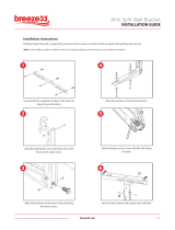
3.5.2Assemblyofmattresssupport
1.Lockthebrakes.
2.Connecttheplugtothemainssocket.
3.
a.Takethehandcontrol.
b.Tiltthelowerpartofthebedinoverthesheararms
(whileitisleaningonthebedendattachments).
c.Holditandusethehandcontroltolowerthebed
untilthesnaplocksarettedonthesheararms
pivots.
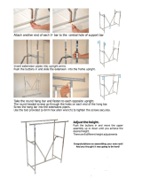
4.
Pushthesectionslightlytowardsthemiddleuntilthe
snaplocksareactivatedwithaclickingsound.Letit
leanasshownintheimage.
Makesurethesnaplocksareproperlyengaged
beforeproceeding.Ifnot,turntheredbuttons
anti-clockwisetolock.
5.Moveovertotheupperpartofthemattresssupport.
101577126-H

Assembly
6.
a.Takethehandcontrol.
b.Fromtheuprightposition(restingonthebedend
attachments);tipthesectioninoverthecontrol
box.
c.Usethehandcontroltoraisethebeduntilthe
squareplasticguidesonthesheararmsconnect
withtheguidewaysonthemattresssupportframe.
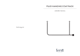
Bedwidth85,
90and105cm
ThearrowBonthe
baseframeandthe
weldingpointAonthe
sheararmscrossbar,
mustbeinline.
Bedwidth120
BTheweldingpoint
onthebaseframe
Dandthewelding
pointContheshear
armscrossbar,must
beinline.
7.
a.Liftupthelowersectionofthemattresssupport
uptoahorizontalpositionandholditthere.
b.Lifttheupperpartofthemattresssupportslightly
andttheinsertsintheopeningsofthesidetubes.
c.Lettheinsertsrestintheopenings.
8.Moveovertothebedheadend.
9.
Lifttheupperhalfofthemattresssupportandpushit
completelyinovertheinserts.
10.Lockthemattresssupportinthemiddle:
Bedwidth85and90:
Pushdowntheseat
section.
Bedwidth105and120:
Tightenthe
nger-screws,under
thesidetubesoneach
sideofthemattress
support.
11.Connectallplugsfromthesectionmotorsinthe
controlbox.
12.Attachthelockingcamovertheplugs.
IMPORTANT!
Afterassemblyofthemattresssupport,check:
–thatallplugs(motorsandhandcontrols)
arecorrectlyconnectedtothecontrolunit
accordingtotheprintedsymbols.
–thatbothsectionsofthemattresssupport
arecompletelypushedtogetherandtheseat
sectioncompletelydown(locked).
–thatbedendsarecorrectlyattachedandthat
themattresssupportisattachedtotheshear
arms(snaplockengaged).
3.5.3Disassemblyofmattresssupport
BeforeDisassemblyofthebed;
•Ensurethatthecastorsintheheadendofthe
bedarepointingtowardsthecenterofthe
bed.
•Usethehandcontroltoadjustittothecorrect
ergonomicheight:
Bedwidth85,
90and105cm
ThearrowBonthebase
frameandthewelding
pointAonthesheararms
crossbar,mustbeinline.
Bedwidth120
BTheweldingpoint
onthebaseframeDand
theweldingpointCon
thesheararmscrossbar,
mustbeinline.
1.Lockthebrakes.
2.Dismounttheaccessories(bedends,siderails,lifting
poleetc).Leavethebedendattachmentsinplace.
3.Disconnectthemainpowerbyunpluggingitfromthe
mainpowersocket.Onthewashablebed(IPx6w)also
removethepowerplugfromthecontrolbox.
1577126-H
11

Invacare®SB®755
4.Removethelockingcamfromthecontrolunitand
disconnectallplugsexceptthehi/loandthehand
control.
5.Loosenthewiresandmakesurenowiresaresqueezed
betweenmovingparts.
6.Releasethemattresssupportinthemiddle:
Bedwidth85and90:
Pulltheseatsectionup.
Bedwidth105and
120:Removethe
nger-screws,under
thesidetubesoneach
sideofthemattress
support.
7.
Standattheendoftheupperhalfofthemattress
support,holdthesidesontheframeandpullit
straightoutuntilitcomestoastop.
8.
Tipitgentlyontotheoorwhileholdinginthelower
halfofthemattresssupport(toavoidscratchingthe
frame)andletitrestonthebedendattachments.
9.
Tiptheparttoanuprightposition(onthebedend
attachments)andfoldoutthebackrestuntilitisin
balanceandletitstandaside.
10.Pluginthemainpowerpluginthecontrolboxand
connectthemainpower.
11.Moveovertothelowerpartofthemattresssupport.
12.Putthehandcontrolwithinreach.
13.
Liftthethigh/legsectionuptoreachthesnaplocks.
Pulloutthered,squarelockingbuttonsandturnthem
clockwise,untiltheystayout.Foldbackthethigh/leg
section.
14.
Standinthefootendofthebed.
a.Putyourfootonthebaseandholdthesidesof
theframe
b.Liftthesectionslightlyupandpullitbackwards
untilitunlocksandleansonthesheararmspivots.
Don’tpullitcompletelyoff.
15.
a.Holditsteadyandpullitslightlybackwardstokeep
itoutofthesnaplocks.
b.Lowerthebedwiththehandcontrolandtipthe
bedfootenddowntotheoor,untilitrestson
thebedendattachments.
12
1577126-H

Assembly
16.
Tipuptoanuprightposition(thighsectionupwards).
Foldoutthethigh/legsectionuntilitisinbalanceand
letitstandaside.
17.
3.6Sheararms(dismountable)
CAUTION!
Riskofpersonalinjury
Personalinjurycanoccurifthesnaplock
betweenthebaseandthesheararmisnot
correctlyengaged.
–Securethesnaplock.
IMPORTANT!
Ifwiresgettrappedbetweenthebaseandthe
sheararmtheycangetdamaged.
–Makesurethewiresrunfreefrommoving
parts.
3.6.1Assemblyofsheararms
1.Lockthebrakes.
2.Takeholdofthehandleonthesheararms.
3.
Liftthesheararmintothebase,restingontheoor.
4.
Carefullylowerthesheararmintoplaceholdingthe
handle.
5.Insertitintotheguidewaysonthebase.
6.Makesurethesnaplockisengaged..
3.6.2Disassemblyofsheararms
1.Lockthebrakes.
2.Usethehandcontroltolowerthesheararms
completelydown.
3.
Takeholdofthesmallhandlelocatednexttothe
controlswithonehand.
4.Loosenthelockingpin
5.Liftthesheararmtoanuprightposition.
6.
Turnthesheararmandholdittowardsthebody
beforelifting.
7.Liftthesheararmsoutofthebase.
3.7Wiring
IMPORTANT!
–Thecablesmustbemountedinsuchaway
thattheyarenothangingontheooranddo
notblockthecastors.
Ifthebedisequippedwithawashablecontrol
unit,itislocatedontheoppositesideofthe
actuator .Topluginthecables,thelidofthe
controlunitneedstobeopenedandclosedagain
afterwards.Theroutingofthecablesissimilarto
thenon-washablecontrolunit.
•Checkthewiringbyoperatingthemotorsofthebed
totheirouterpositions.
•Thereisnoriskofsqueezingthewireswhencorrectly
installed.
1577126-H13

Invacare®SB®755
•Itisnormalforcablestostrechslightlyaftersome
usage.
•Thewiresareequippedwithplugsatbothsections
andcanbereplacedindependently(exceptforthe
heightmotor).
IMPORTANT!
IPProtection
Thehandcontrol,controlunitandmotorsare
protectedaccordingtoIPx4,IPx6orIPx6w.
–ToguaranteetheIPprotection,alockingcam
mustbeinstalledonthecontrolunit.
3.8Storageofdisassembledbedon
baseframe
CAUTION!
Riskofpersonalinjuryordamagetoproperty.
Ifthedistancepinisnotproperlyattachedbed
partsmayfalloffthetrolley.
–Makesurethedistancepiniscorrectly
attachedbetweenthemattresssupport
sectionsbeforehanginganythingonthe
hooks.
Mountingthepartsonthebaseframe
1.Lockthebrakes
2.Usethehandcontroltolowerthesheararms
completelydown.
3.Disconnecttheplugfromthemains.
4.Placethepowerwireandthehandcontrolsecurely
aroundthesheararms.
5.Hangonemattresssupportsectiononeachside,on
thehooksonthebaseframe.
6.LiftthedistancepinoutofitsplaceholderBand
swingitovertotheoppositeside.
7.Placethemotorwiresaroundtheslatsoneach
mattresssupportsections.
8.PulloutthecotterpinAandpushthedistance
pin,fromunderneath,intothebracket.Letgoof
thecotterpinandmakesurethatthespringisfully
engagedanddistancepinproperlyfastened.
9.FolddownbothtransporthooksCfortheaccessories.
10.Placethebedendsandsiderailsonthehooks.
11.Placethemattressbetweenthesections.
12.PlacetheliftingpoleinthetubeDonthebaseframe.
Makesureallwiresandthehandcontrolare
properlysecured,toavoiddamageduringtransport.
Dismountthepartsfromthebaseframe
1.Lockthebrakes.
2.RemovetheaccessoriesfromthetransporthooksC.
3.Foldupthetransporthooks.
4.PulloutthecotterpinAandremoveitfromthe
bracket.Swingitovertotheoppositesideandpress
itintoitsplaceholderB
5.Liftoffthemattresssupportsections.
3.9Mattressretainers
Mattressretainerskeepthemattressinplacewhenthe
userismovinginthebedorin/outofbed.Theyalso
enablethemattresstofollowthemovementswhen
sectionsarepositionedwiththehandcontrol.
WARNING!
Riskofinjury
ifthemattressretainersareremoved,the
mattresscanslidesidewaysandcausetheuser
tofalloutofthebedorgettrappedinthebed.
–Alwaysusemattressretainersandbecareful
toputthembackafteranyadjustments.
–Alwaysusetherightsizeofretainers
dependingonthebedwidth.
–Alwaysplacetheretainersatthecorrect
placeaccordingtoinstruction.
Themattressretainerscomeindifferentsizes
dependingonthewidthofthebed.
Mountingmattressretainers
1.
Clipthemattressretainerdown,overthemattress
frame.
Makesurethattheendwiththehookis
underneaththelaths.
Forbedwidth85–90cm
14
1577126-H

Assembly
Fromheadendofthebed-Placethemattressretainers
Abetweenlath3and4.
Fromfootendofbed-PlacethemattressretainersB
betweenlath3and4.
Forbedwidth105-120
Fromheadendofthebed-Placethemattressretainers
Abetweenlath3and4.
Fromfootendofbed-PlacethemattressretainersB
betweenlath4and5.
3.10Limitationcrossbar
WARNING!
Riskofsqueezingorentrapment
Theusercangetcaughtorsqueezedwhenthe
legsectionisloweredbeneaththeframeof
thebed
Takespecialcarewhentheuserisrestlessor
confused.
–Toavoidtheriskofentrapmentalimitation
crossbarcanbettedunderthelegsection
ofthemattresssupport.
Mountingthelimitationcrossbarunderthelegsection
1.
Liftthelegsectionofthemattresssupporttofree
thebase.
2.
Fitthecrossbarintoplaceandtightenthescrews.
3.
Whenproperlyinstalled,thelegsectionofthe
mattresssupportleansonthecrossbar.
3.11Mattresssupportextension
Forpatients,tallerthantwometersitisrecommendedto
extendthebedwithamattresssupportextension.
WARNING!
Riskofinjury
Theusercanfalloutofbed,gettrappedor
suffocated.
–Alwaysextendthemattresswhenextending
bed.
–Theremustbeadistanceofmorethan2,5
cm,betweenthebedendandthemattress
bow,toavoidentrapmentofngers.
WARNING!
Riskofinjury
Theusercangethitbytheliftingpoleorfall
outofbed.
–Alwaysmakesuretotightenthescrewsfor
themattresssupportextension.
Thebedcanbeextended5or10cminbothendsofthe
bed–toamaximumextensionof20cm.
Allenkey
1577126-H15

Invacare®SB®755
1.Dismountthesiderail(s)andliftingpole(bedhead
end).
2.Extendthebedinthefootend
a.LoosenthescrewsAonthebedendattachments.
b.PulloutthebedendattachmentsB5or10cm,
andre-tightenbothscrewsA.
c.LoosenthescrewsConthemattressbowDand
pullitouttomatchtheextension.Makesurethere
isatleast2,5cmbetweenthemattressbowand
thebedend.
3.Extendthebedintheheadend
a.LoosenthescrewsAonthesidetubeofthe
mattresssupportframe.
b.PulloutthecrosstubeB5or10cm,andre-tighten
bothscrewsA.
4.Replacethemattressorputinattingmattresspiece.
5.Mountthesiderail(s)andliftingpole(bedheadend).
Loosemattresspiecesshouldalwaysbettedin
thefootendofthebed.
3.12BumperwheelsonEmmabed
ends
Bumperwheelscannotbemountedontoother
bedends.
Thebumperwheelscanbemountedintwodifferentways.
Seeillustrations.
1.Mountthebushinginthebumperwheel
2.Fastenthebumperwheelwithascrewintothebed
end.
3.13Accumulatorbackup
(onlyfornon-washableversionofthebed)
Bedsequippedwithaaccumulatorhasanadditionalbox
AnexttothecontrolunitB.Thebackupensuresthatthe
bedcanbeadjustedduringapowerfailureortransport.
AB
IMPORTANT!
Lowaccumulatorcapacity
–Whentheaccumulatoronlyhascapacityleft
foronemoreliftingcycle,thecontrolbox
willmakeanaudiblesound,whenusingthe
handcontrol.
Mountingthebackupbattery
1.Installthebox,onthebed´sbaseframe,nexttothe
controlunitB.
2.Connectthecabletothecontrolunit.
Chargingthebatteries
WARNING!
Riskofexplosion
Oldorfaultyaccumulatorsmaygeneratean
explosivegasmixtureduringcharging.
–Theaccumulatorboxisprovidedwithvents
toensureadequateventilationofthebox.
Donotblockorcoverthevents,asthismay
resultinpressurebuilt-upandtheriskof
explosion.
1.Connectthecontrolunittothemains.
•Thecontrolunitmustbeconnectedtothe
mainsfor24hourspriortorstuse.
•Accumulatorsmustbecharged,atleast,every
6monthsformaintenancepurposes.
Preventivemaintenance
Frequent,suddendischargesreducethebackup’s
life.
Werecommendtheaccumulatorbetestedatleastonce
ayear .
Accumulatorsarenotdamagedbycontinuousconnection
tothemains.
Exchangingtheaccumulators
IMPORTANT!
Accumulatorback-up
–Oldaccumulatorsmustbereturnedto
Invacareorrecycledascarbatteries
•Accumulatorshavetobeexchangedafter4years.
Dependingonhowthebackupisusedtheexchange
mayhavetotakeplaceearlier .
161577126-H

Assembly
•Accumulatorsmustbeexchangedassets.
•Accumulatorsmustbereplacedwithaccumulators
ofthesametypeormechanicallyandelectrically
compatibleaccumulators(12V-1,2Ah).
•Accumulators,inaset,musthaveidenticalproduction
codes.
Priortoinsertionmakesurethattheaccumulator
setiscorrectlyconnectedaccordingtothedrawing
(intheaccumulatorbox),andthatnoneofthe
connectionsareloose.
1577126-H
17

Invacare®SB®755
4Servicing
4.1Generalservicinginformation
IMPORTANT!
–Themattresssupportmustbesupported
duringserviceinspections,toprevent
accidentallowering.
–Onlypersonnelwhohavereceivedthe
necessaryinstructionsortrainingmay
performserviceandmaintenanceofthebed.
–Afterreconditioningthebed,orifbed
functionschange,servicemustbecarriedout
accordingtothechecklist.
Aservicecontractcanbemadeinthecountries,where
Invacare®hasitsownsalescompany.Incertaincountries
Invacare®offerscoursesinserviceandmaintenanceof
thebed.Sparepartslistsandadditionalusermanuals
areavailablefromInvacare®.
BeforeUse
•Ensurethatallmanualandelectricalpartsfunctions
correctlyandareinasecurestate.
•Check,byraisingandloweringthebed,thattheshear
armsrunsmoothlyintheguideways.
Afterthreemonths
•Ensurethatallmanualandelectricalpartsare
functioning,andtightenbolts,screws,nuts,etc.
Everyyear
•Werecommendasafetytestcomprisingthemotors’
performanceandmechanicalstate.
Everysecondyear
•Westronglyrecommendaserviceaccordingtothe
belowchecklistaftertwoyearsofnormaluseand
theneverysecondyear.
Motors,handcontrolandcontrolunitsareserviced
byexchangingthefaultypart.
4.1.1Checklist-Maintenance
Checkpoints
qCirclips,cotterpinsandplasticxingring-properly
lockedandintact.
qScrews-tightened.
qWeldings-intact.
qChecktheguideways-nobending.
qChecktheguidewaysreinforcement-properly
fastened.
qSideraillockingandmovingsystem-properlylocking
andrunningsmoothly.
qCastorttings-tightened.
qCastorbrakes-lockingproperly.
qHeightadjustmentmotor-runningproperly.
qBackrestmotor-runningproperly.
qThighsectionmotor-runningproperly.
qLegsectionmotor-runningproperly.
qWires-correctlywiredandundamaged.
qElectricplugs-undamaged.
qCableinsulationandactuatorhousings–nocracks
ordamages.
qDamagedcoating-repaired.
qLinesiderailstraps-notfrayedorcracked.
qAccessories-correctlyassembledandcorrectfunction.
4.2Inspectionafterrelocation-Prepare
fornewuser
IMPORTANT!
Whenthebedhasbeenrelocated;beforegiven
toanewuserithastobethoroughlyinspected.
–Inspectionmustbedonebyatrained
professional.
–Forregularmaintenanceseemaintenance
chart.
4.2.1Checklist-Afterrelocation
Checkpoints
qCheckthattheliftingwedgerunsinthecentreofthe
supportrolls;upperandlower.
qCheckthatthelockingbetweentheliftingwedgeand
pistonfromthemotorissecure(pipepinscorrectly
mounted).
qCheckthatthesidetubesofthemattresssupportare
fullyinserted,alignedandlocked.
qCheckthatthelatches,lockingthemattresssupport
onthesheararms,areproperlyengaged(redbutton
onthemattresssupport).
qCheckthelockingofthemotors(pipepinscorrectly
mounted).
qChecktheelectronicwiringforthemotors(wiresnot
squeezed).
qCheckthattheenclosingofthemotorsareintact(no
cracksthatenablesuidstopierce).
qCheckthatthelockingcamisproperlymountedover
thecontactsinthecontrolbox.
qCheckthesectionsofthemattresssupportbyusing
thehandcontroltoactivateallfunctionsofthe
movingparts.
qCheckthefunctionofthebrakes.
qCheckthatthesnaplocksonthebedendsare
properlylocked(pinallthewayin=locked)
qCheckthelockingfunction(s)ofthesiderails.
qCheckthatallbedslatsareintactandnotloose.
4.3CleaningandDisinfection
4.3.1GeneralSafetyInformation
CAUTION!
Riskofcontamination
–Takeprecautionsforyourselfanduse
appropriateprotectiveequipment.
CAUTION!
Riskofelectricshockandproductdamage
–Switchoffthedeviceanddisconnectfrom
mains,ifapplicable.
–Whencleaningelectroniccomponents
considertheirprotectionclassregarding
wateringress.
–Makesurethatnowatersplashestotheplug
orthewalloutlet.
–Donottouchthepowersocketwithwet
hands.
181577126-H

Servicing
IMPORTANT!
Wronguidsormethodscanharmordamage
theproduct.
–Allcleaningagentsanddisinfectantsused
mustbeeffective,compatiblewithone
anotherandmustprotectthematerialsthey
areusedtoclean.
–Neverusecorrosiveuids(alkalines,acidetc.)
orabrasivecleaningagents.Werecommend
anordinaryhouseholdcleaningagentsuchas
dishwashingliquid,ifnotspeciedotherwise
inthecleaninginstructions.
–Neveruseasolvent(cellulosethinner,
acetoneetc.)thatchangesthestructureof
theplasticordissolvestheattachedlabels.
–Alwaysmakesurethattheproductis
completelydriedbeforetakingintouseagain.
Forcleaninganddisinfectioninclinicalorlong-term
careenvironments,institutionalhygieneguidelines
apply.
4.3.2CleaningIntervals
IMPORTANT!
Toreveallooseorwornparts,enhancesmooth
operationandpreventcontamination:
–Cleananddisinfecttheproductthoroughly
andonaregularbasis.
–Cleananddisinfecttheproductbeforeand
afteranyserviceprocedure,accordingtothe
instructionsinthischapter .
–Cleananddisinfecttheproductwhenithas
beenincontactwithanybodyuids.
4.3.3Cleaningbyhand
Electricalcomponents
•Method:Wipeoffwithawetclothorsoftbrush.
•Max.temperature:40°C
•Solvent/chemicals:Water
•Drying:Wipedrywithasoftcloth
Metalcomponents
•Method:Wipeoffwithawetclothorsoftbrush.
Watermaybepressurized,butnothighpressureor
steam.
•Max.temperature:40°C
•Solvent/chemicals:Ordinaryhouseholdcleaning
agentsandwater.
•Drying:Wipedrywithasoftcloth
Wood(includingtextilestrapsonsiderails,ifexisting)
•Method:Wipeoffwithawetclothorsoftbrush.
•Max.temperature:40°C
•Solvent/chemicals:Ordinaryhouseholdcleaning
agentsandwater.
•Drying:Wipedrywithasoftcloth
Textiles(includingupholsteryandmattresses)
•Seeattachedlabeloneachproduct.
4.3.4Cleaninginautomaticwashingsystems
IMPORTANT!
Onlycertaincomponentsoftheproducttolerate
cleaninginautomaticwashingsystemsorwith
highpressurecleaningequipment.
–Thewashabilityofthecomponentsmustbe
determinedbyauthorizedpersonnel.
–Ifthecomponentscannottoleratecleaning
inautomaticwashingsystems,withhigh
pressurecleaningequipmentorifitisunclear,
theymustbecleanedbyhand.
TheIPclassicationdeterminesthewashabilityofa
electricalcomponent.TheIPclassicationofeachelectrical
componentisstatedonitsseriallabel.
•ElectronicsclassiedIPx4and/orIPx6mayNOTbe
washedwithhigh-pressurecleaningequipmentorin
aautomaticwashingsystem.
•ElectronicsclassiedIPx6wcanbewashedwith
high-pressurecleaningequipmentorinaautomatic
washingsystem.
Preparation
Beforewashingwithhigh-pressurecleaningequipmentor
inautomaticwashingsystems,performthefollowing:
qRemoveallelectronicsnotclassiedasIPx6w.
qRemovepowerplugfrommains.
qRemovealltextiles(includingmattressandupholstery).
qRemoveallwoodenparts.
qRemovealuminiumsiderails.
qMakesureallplugsonthebedareplacedintheir
socketsduringwashing.
qProtectedalldisconnected(loose)plugswithplastic
coversandallemptysocketse.g.withblindplugs.
qRunthemotorsallthewaydown/intopreventthem
fromcalciumsedimentationandcorrosion.
qPlacethebedinoneofthefollowingways:
PlacedonitscastorsPlacedonthesideon
atrolley
Washing
•Maxtemp:70°C
•Solvent/chemicals:Mildcleaningsolution
•Max.Duration:2min
•Maxpressure:8Bar,withanozzledistanceof30cm
frompart
Rinsing/ushing
•Maxtemp:85°C
•Solvent/chemicals:Neutralrinsingsolution
•Max.Duration:20sec
•Maxpressure:8Bar,withanozzledistanceof30cm
frompart
Drying
•Method:Inwashingsystemordryingcabinet
•Maxtemp:50°C
1577126-H19

Invacare®SB®755
•Max.Duration:10min
Alternatively,letthebeddryinroomtemperature.
Dependingontheplacementofthebed,performoneof
thefollowingprocedures,toallowthewatertorunout
ofthetubes:
•Bedplacedonitscastors
1.Placethethigh/legsectionAandthebackrestB
inanuprightposition.
2.Tiltthebedbyplacinganobject(about10cm)
Cundertheheadendcastors.
•Bedplacedontrolley
1.Tiltthebed/trolleytooneside,byplacingan
object(about10cm)underthecastors.Leaveit
for5minutes.
2.Tiltthebed/trolley,totheotherside,byplacing
anobject(about10cm)underthecastors.Leave
itfor5minutes.
4.3.5Afterwashing
Necessaryprecautionsbeforetakingthebedintouse
again
1.Inspectcarefullyforremainingwaterandwipeoff
withadrycloth.Especiallychecktheguideways.
2.Testallelectricfunctions.
3.Lubricatethebedaccordingtolubricationchart
4.ReconditionthebedaccordingtosectionInspection
afterrelocation-Preparefornewuser.
4.3.6Disinfection
IMPORTANT!
–Onlyusedisinfectantsandmethodsapproved
byyourlocalinfectioncontrolinstitutionand
followyourlocalinfectioncontrolpolicy.
–Additionalinformationonrecommended
disinfectantscanbefoundon
https://vah-online.de/en/for-users.
•Method:Wipeoffwithamoistened,rmlywrung
cloth.
•Solvent/chemical:Ordinaryhouseholddisinfectant.
•Drying:Allowtheproducttoair-dry.
4.4Lubrication
1
1
2 2
2 2
3
4
Werecommendlubricatingthebedaccordingtothe
followingtable:
PartofbedLubricationmethod
1
Bearingsforlifting-and
sheararms
Oil(medicallyclean)
2
Motorsuspension
Oil(medicallyclean)
3
Glidingshoesandguideways
Grease
4
Axlesandrollsforsheararms
(axlemustbedismounted)
Grease
IMPORTANT!
TheglidingshoesintheLinesiderails´gliding
systemmovesluggishlyiflubricatedwithoil.
Fororderingofcorrectoilandgrease,please
contactyourInvacaredealer.
4.5Adjustingmisalignedplatformtubes
Thisinstructiononlyappliestobeds85–90cmwide.
Intheeventthatthesidetubesaremisalignedinthe
assembly,theinsertscanbeadjustedforbettert.
201577126-H
/